CN1065631A - Mountain bike - Google Patents
Mountain bike Download PDFInfo
- Publication number
- CN1065631A CN1065631A CN92100433.8A CN92100433A CN1065631A CN 1065631 A CN1065631 A CN 1065631A CN 92100433 A CN92100433 A CN 92100433A CN 1065631 A CN1065631 A CN 1065631A
- Authority
- CN
- China
- Prior art keywords
- mentioned
- joint
- folding
- blade
- bicycle
- Prior art date
- Legal status (The legal status is an assumption and is not a legal conclusion. Google has not performed a legal analysis and makes no representation as to the accuracy of the status listed.)
- Pending
Links
Images


Classifications
-
- B—PERFORMING OPERATIONS; TRANSPORTING
- B62—LAND VEHICLES FOR TRAVELLING OTHERWISE THAN ON RAILS
- B62K—CYCLES; CYCLE FRAMES; CYCLE STEERING DEVICES; RIDER-OPERATED TERMINAL CONTROLS SPECIALLY ADAPTED FOR CYCLES; CYCLE AXLE SUSPENSIONS; CYCLE SIDE-CARS, FORECARS, OR THE LIKE
- B62K15/00—Collapsible or foldable cycles
- B62K15/006—Collapsible or foldable cycles the frame being foldable
-
- Y—GENERAL TAGGING OF NEW TECHNOLOGICAL DEVELOPMENTS; GENERAL TAGGING OF CROSS-SECTIONAL TECHNOLOGIES SPANNING OVER SEVERAL SECTIONS OF THE IPC; TECHNICAL SUBJECTS COVERED BY FORMER USPC CROSS-REFERENCE ART COLLECTIONS [XRACs] AND DIGESTS
- Y10—TECHNICAL SUBJECTS COVERED BY FORMER USPC
- Y10T—TECHNICAL SUBJECTS COVERED BY FORMER US CLASSIFICATION
- Y10T403/00—Joints and connections
- Y10T403/32—Articulated members
- Y10T403/32254—Lockable at fixed position
- Y10T403/32262—At selected angle
- Y10T403/32319—At selected angle including pivot stud
- Y10T403/32327—At selected angle including pivot stud including radially spaced detent or latch component
-
- Y—GENERAL TAGGING OF NEW TECHNOLOGICAL DEVELOPMENTS; GENERAL TAGGING OF CROSS-SECTIONAL TECHNOLOGIES SPANNING OVER SEVERAL SECTIONS OF THE IPC; TECHNICAL SUBJECTS COVERED BY FORMER USPC CROSS-REFERENCE ART COLLECTIONS [XRACs] AND DIGESTS
- Y10—TECHNICAL SUBJECTS COVERED BY FORMER USPC
- Y10T—TECHNICAL SUBJECTS COVERED BY FORMER US CLASSIFICATION
- Y10T74/00—Machine element or mechanism
- Y10T74/20—Control lever and linkage systems
- Y10T74/20576—Elements
- Y10T74/20732—Handles
- Y10T74/20762—Shaft connections
- Y10T74/20768—Engine starter type
- Y10T74/20774—Holders
-
- Y—GENERAL TAGGING OF NEW TECHNOLOGICAL DEVELOPMENTS; GENERAL TAGGING OF CROSS-SECTIONAL TECHNOLOGIES SPANNING OVER SEVERAL SECTIONS OF THE IPC; TECHNICAL SUBJECTS COVERED BY FORMER USPC CROSS-REFERENCE ART COLLECTIONS [XRACs] AND DIGESTS
- Y10—TECHNICAL SUBJECTS COVERED BY FORMER USPC
- Y10T—TECHNICAL SUBJECTS COVERED BY FORMER US CLASSIFICATION
- Y10T74/00—Machine element or mechanism
- Y10T74/20—Control lever and linkage systems
- Y10T74/20576—Elements
- Y10T74/20732—Handles
- Y10T74/2078—Handle bars
- Y10T74/20792—Folding or adjustable
-
- Y—GENERAL TAGGING OF NEW TECHNOLOGICAL DEVELOPMENTS; GENERAL TAGGING OF CROSS-SECTIONAL TECHNOLOGIES SPANNING OVER SEVERAL SECTIONS OF THE IPC; TECHNICAL SUBJECTS COVERED BY FORMER USPC CROSS-REFERENCE ART COLLECTIONS [XRACs] AND DIGESTS
- Y10—TECHNICAL SUBJECTS COVERED BY FORMER USPC
- Y10T—TECHNICAL SUBJECTS COVERED BY FORMER US CLASSIFICATION
- Y10T74/00—Machine element or mechanism
- Y10T74/20—Control lever and linkage systems
- Y10T74/20576—Elements
- Y10T74/20732—Handles
- Y10T74/20834—Hand wheels
- Y10T74/20864—Handles
Abstract
A kind of mountain area bicycle has folding joint, a folding handle assembly and a folding pedal of two alignment on the vehicle frame.Described joint is installed in the gap of tubulose frame member, and comprises two disks, and available two hinged blades that have a fastener to clamp are connected the jointed shaft of two ears on the blade with one.The interlocking rib that prevents that it is pivoted relative to each other is arranged between two ears.Handle assembly has articulated tubulose up and down to regulate part.One cup-shaped unitor constitutes the basis of this adjusted part, and has the recessed head fastener that contains pod to be clipped in down on the adjusting part by one.This two adjustings part has the anchor clamps of similar unitor respectively.
Description
The present invention relates to Folding Bicycle, a folding bicycle with foldable chassis and a collapsible handle device particularly is so that become the packaging body of compact, transportation when facility is not used and storage with the volume-diminished of bicycle.The present invention is specially adapted to (but being not limited to) safety bicycle, or claims " mountain bike ", and wheel and tire are bigger, and the vehicle frame of comparatively robust is triangularity substantially, not only can be used for also can be used for comparison rough riding surface such as path on the highway.
Folding bicycle comes out already, and has used for many years, and different shape and size are arranged, and the method for various folding bicycles is arranged.Wherein a kind of folding bicycle of more generally usefulness is a US Patent the 4th, 433, disclosed in No. 852, its design is to adopt quite little wheel (for example diameter is 16 inches), being installed in one is supporting on the short vehicle frame of handle and seat unit, this vehicle frame is collapsible and stretch upwards so that handle and seat are set on the height that the user asks in advance, and its setting range can be fit to children to becoming the human body type.The small-sized wheel of this patent bicycle and short vehicle frame can be converted into bicycle very compact small-sized packaging body.And door handle device comprises an elongated pillar, and its lower end is hinged on the tilting axis, so that become the kenel from the front to the back when handle is folded down, vertical mid point of this vehicle frame is a pivotally attached, so that front and back wheel is converted into side by side relationship.
Large-scale bicycle also is designed to foldable, but large-scale bicycle makes and collapsiblely be not popular, and may be that it is too complicated and be folded into a lot ofly, also may be that appearance is unbecoming or offend the eye.But this kind bicycle is still popular in car fan voluntarily, and they to a certain degree, take off front-wheel with bicycle " decomposition " at least, just transport or seasoning with this appearance then.But obvious front-wheel and the not enough packaging body that large-sized bicycle is dwindled into easy seasoning or transportation of only taking off.The object of the present invention is to provide to have improved folding characteristics, can be applicable on the various bicycles, and be particularly suitable for possessing the mountain bike of straight handle.
The invention belongs to one the innovation folding bicycle that can fold frame and collapsible handle is arranged, not only the operation letter is fast firm, can make bicycle (comprising large-sized mountain bike) be folded into compact folded state and recovery, also can when folding, keep the standard bicycle outward appearance and be not subjected to the influence (no matter being on vision or the function) of Foldable assembly.In other words, the invention provides a kind of seem, sensuously reach drive to go up non-Folding Bicycle of picture, but when transportation and seasoning, have folding advantage.
For this reason, the present invention's bicycle has a foldable chassis, have at least one vertical vehicle frame, normally two, being placed at firm folding joint in the gap of frame by one is flush relationship and links together, other has a collapsible handle assembly set, be fixed on the normal operating position in the mode that is difficult for discovering, and easily unclamp and relying on vehicle frame to settle around a unconspicuous hinge changes a position that does not counteract from front to back over to, this hinge is the side location along handlebar posts, vehicle frame hinge and handle hinge (when engaging) all have the fastener of recessed non-protruding-type position, and an available general tool unclamps fast easily, and this instrument can be used for adjusting handling position and seat.
In particular, such as among the present invention shown in the preferred embodiment of analysis, the folding joint of each novelty comprises two hinge seats that flush, be located between the vehicle frame in the crack, the hollow two ends that are preferably in vehicle frame tightly embed connector and an object against these ends are arranged, and two hinged blades side by side, be fixed on the hinge mount and and cross the extending longitudinally of above-mentioned gap at bicycle from its relative edge.Hinged blades is to be bonded together with pivot by a swivel pin, can swing mutually when being folded into side by side relationship around a jointed shaft in order to two end portions when frame member, mid point before and after this hinge axis is positioned between wheel seat, this is vertical when the normal direct control position of bicycle, hinged blades then is horizontal.When desire is fixed on open mode with vehicle frame, anchor clamps (connect blade and be screwed into another blade for there being a fastener to pass a hinge at this) clamp the relative lock face of two blades, other has the relative supporting member of interlocking to be formed on these faces, and to prevent being sandwiched in a time-out at these faces, generation relatively moves.One swivel pin allows blade in relative separately the moving of the axial generation of hinge, is convenient to fold so that these supporting members are separated.
Suitable hinged blades is the projection of thickening, has the half-cylindrical middle body concordant with frame member, is the pipe of a circular cross-sectional shape basically, and has along the outstanding ear of side direction of the side setting of frame member.The recessed wherein middle body of head and the fastener that clamp fastener are screwed in the pod of another middle body, and pivot pin then is arranged on wherein on the side among two ears, at the rib that interlocking is then arranged on the adjacent surface of two ears on another side in addition.Fastener is borrowed the sky of its head recess and projection to be dynamically connected and is pulled, preventing the loss that when unclamping, meets accident, this suitable head be shaped to socket type, can engage as the hexagonal plate palmistry by a non-circular driven tool.
There is a kind of vehicle frame of bicycle that vertically frame member is arranged up and down, is called " going up pipe " and reaches " pipe down ", in crack between the common jointed shaft alignment, two similar folding joints are being set.Because pipe is to tilt to the back lower place from forked type pole in the place ahead of vehicle frame under the representative type, the both ends of the hinged blades of following folding joint and following pipe are an angle configurations.
On one side of the folding handles assembly set of novelty of the present invention an incline hinge is arranged, so that be converted into as the bicycle of patent as described above by the attitude behind the forward direction, but there is no the cup-shaped substrate of the elongated pole or the pole of this bicycle, and unshowy anchor fitting in the bulk-breaking of a recessed handlebar stem arranged, so that the mode identical with the fastener of fixing vehicle frame hinge operated.In the embodiment shown, securing device is included in the unitor between the upper and lower part of handle assembly, and a fastener that has that stretches into downwards on the door handle device bottom in the end.Form a non-circular pod in the upper end of the preferably recessed unitor of fastener head, in order to admit a driven tool between the operation vehicle frame folding joint fastener.This instrument also can be used for other bicycle mechanisms, for example the seat is moved up.
Incline hinge is connected between unitor and the bottom, allows handle to fold when separating with pod with convenient fastener, and fastener has sky and is dynamically connected and makes it and connector keeps engaging when leaving pod.In addition, handle assembly has the extension mechanism that can adjust forward, between unitor and handle, and has an extension mechanism that can adjust upward to be positioned at unitor below, and it is more effective to make adjustments of operating position of handle compare existing handle assembly.
The common multi-functional Folding Bicycle of creating of above-mentioned these features, its outward appearance in fact, sensation and driving are gone up and non-Folding Bicycle does not have difference, but provide letter speed and firm operation to fold mechanism, above and other features of the present invention can easilier from following detailed description in conjunction with the accompanying drawings be understood.
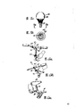
Fig. 1 is the lateral plan of essential part that explanation the present invention has the Folding Bicycle of novel characteristic, and for clarity sake part takes off the sixth of the twelve Earthly Branches, and wheel only is represented by dotted lines;
Fig. 2 is the plan view from above of this Folding Bicycle;
Fig. 3 is the plan view from above that is the bicycle of folded state;
Fig. 4 a to 4e is the diagram of reduce in scale of the step of the expression state that bicycle is folded into Fig. 3 from the state of Fig. 2;
Fig. 5 a and 5b are respectively lateral plan and bottom plan view, and show the instrument of the fold mechanism of operation Collapsible bicycle with magnification ratio;
Fig. 6 a to 6c is the part diagram perspective drawing of the instrument occupation mode of Fig. 5 a and 5b, upwards reaches extending upward of extension forward and seat cushion in order to operating handle;
Fig. 7 is an amplifier section transparent view of going up the folding joint place of pipe, has removed part among the figure for simplicity's sake, and this joint is the serviceability in closure;
Fig. 8 is the part transparent view of the amplification and the part removal of the upward folding joint of pipe, and this joint is to open folded folded state;
Fig. 9 is the amplifier section transparent view of the folding joint of following pipe, and a plurality of parts are cut among the figure for simplicity's sake, and this joint is the serviceability of cutting out;
Figure 10 is the amplifier section transparent view of the folding joint in the following pipe, and a plurality of parts are cut among the figure for simplicity's sake, and this joint illustrates local open state;
Figure 11 is the amplifier section lateral plan of the foldable bicycle handle assembly of Fig. 1 and 2, and for simplicity, part is broken away among the figure, and shows the mobile position and the relevant portion of vehicle frame with thinner long and short dash line;
Figure 12 is the view sub-anatomy of handlebar stem assembly set, and the handle base from end parts on the fork arm (illustrating with exploded drawings in the figure lower right corner) to the figure upper left corner, some part part remove and illustrate with cutaway view.
Below most preferred embodiment of the present invention is described.
Integral structure
As shown in FIG., in Fig. 1 and 2, know and show bicycle 10 of the present invention, " going out district's bicycle " of promptly calling, have the vehicle frame 11 of suitable weight and than contest with the heavier front and back wheel 12 and 13 of cycle wheel, and popular " 10 grades of speed changes " for many years arranged though the present invention is specially adapted to this type of bicycle, should be understood that the present invention is not restricted to this pattern.
The bicycle 10 of diagram has one and is essentially the vehicle frame 11 that traditional design and design-calculated are substantially triangle, comprises a level frame member 14, and common name " is gone up pipe " backwards oblique frame member 15 downwards is called " pipe down "; One connects the vertical type seat pillar 17 of the rear end of this above-mentioned frame member, and one connects its front-wheel pole 18, common name " head pipe ".This pipe carrying front-wheel is normally on a fork 19.This fork from the beginning pipe reaches down towards top rake, and wheel seat 20 is in its lower end, and has leader's assembly set 21 to connect its upper end, is positioned at head pipe top.Live on 23 a seat cushion 22 is installed in an extension, this pillar can stretch in the seat pillar 17, and is fixed by anchor clamps 24.
Being provided with a triangle rear cycle frame structure is used for a trailing wheel 13 and is supported on the wheel seat 5, this rear cycle frame structure comprises a pair of top pole 27, sometimes be called " seat cushion stay ", this slopes down to rear wheel seat to pole backwards from last pipe 14 nearly seat pillars 17, and the below pole 18 of a pair of level arranged, be sometimes referred to as " chain pole ", extend to rear wheel seat from the lower end of seat pillar.This rear wheel seat contains two fabricated sections, and in order to the opposite end (seeing Fig. 2 and 3) of connection rear axle 29, and preceding wheel seat contains two similar parts in order to pillar one front axle 30.
The vehicle frame hinge:
According to the present invention, vehicle frame 11 has two inconspicuous folding joints 38 and 39, pipe 14 and down in the space of pipe 15 and be located on the common jointed shaft 40 in the insertion, and it is concordant with two pipes, two hinge 41(of each joint see Fig. 7) be fixed on the adjacent end portion of joining frame member, and 42,43 of two hinged blades of each joint are placed side by side in this joint and continuous being knotted, so that do relative swing around hinge axis.There is a non-outstanding fastener 44 can be optionally this is stably clipped together blade and can when folding bicycle, it to be separated, is provided with interlocking member,, prevent that effectively it from relatively moving in order to when both clamp in the adjacent both sides of blade.
Particularly two hinge seats of (clearly visible from Fig. 7 to 10) last folding joint 38 respectively comprise a disk, coaxial being connected in the barrel-contoured connector of a roundlet, this connector plugs together in the open end that snaps in pipe, and appropriate (as using hard solder) is fixed therein, the footpath is identical with last pipe outside this disk, each hinged blades 42,43 is positioned at the side that this hinge one separates face from the vertically court of vehicle frame from stretching out in the direction of disk 41, this face is on the y direction of last pipe, under the normal serviceability of bicycle, then be roughly level.
Shown in Fig. 7 and 8, each hinged blades 42,43rd is the projection shape of thickening, preferably and disk 41 monolithic moldings are installed, and has one to be roughly semicircle middle body 47 and two ears 48, on the relative side of this middle body.This two ear slightly outwards is projected into beyond the side of pipe, and circular outer ends is preferably arranged.Jointed shaft 40 is limited by trunnion 49, and this trunnion is a rivet, in a side of its two ears opposite side (see then be the left-hand side from Fig. 7 and 8) head is arranged.Rivet can't be too tight when folding when fastener 44 is released, can allow joint that the clearance of small amount of vertical is arranged.This clearance can make interlocking member connect and throw off, this interlocking member is rib that engages one another and the chase 50 that is positioned on the adjacent surface of two ears 48 on joint rivet 49 opposite side, the shape of these ribs and chase is complementary, but both driving fits when closed as shown in Figure 7 have the action of opening to prevent hinge with convenient joint.From Fig. 8 and 10 as can be seen, the middle body of the clamping surface of each hinge leaf 42,43 is recessed into, to avoid interference end clips together.
For the face that rib and chase are arranged 50 with interlocking clamps, fastener 44 is one the bolt of bar 51 to be arranged, this bar 51 passes a vertical channel by top projection 42 centers, this fastener 44 has a head 52 to place an alcove at this projection top, this alcove is formed by above-mentioned passage with on strengthening, and this bar 51 is screwed into negative thread passage 54(Fig. 8 of the centrally aligned of a pair of and lower protruding block 43) in.Head 52 at fastener also has a pod 54 in order to admit a hex-shaped drive tool, and this binding bolt is also borrowed the sky between bolt shank and the projection to be dynamically connected and is pulled, limited up-and-down movement is done in permission between locking shown in Fig. 7 and 8 and release position, but prevents that bolt breaks away from projection fully.The annular that can have interlocking in the ear around the rivet is strengthened ridge and chase (not shown), to stop projection shifted laterally in the joint of closure.
Following folding joint 39(sees Fig. 9 and 10) the similar folding joint 38 of going up, but down hinged blades under to manage the orientation of the longitudinal axis then inequality, these hinged blades and down folding joint other likes all before the cooresponding label of face represent.Because down pipe 15 and last pipe 11 and jointed shaft 40 are an angle, hinge leaf 42 and opposite face is arranged and the longitudinal axis of following pipe be some angle and be positioned at last folding joint separate parallel one the separating on the face of face.Two to separate face be level at bicycle during in normal operating state for this.
For this reason, following hinge leaf 42 ' and 43 ' opposite face become horizontal surface in fact, it intersects with following Guan Chengyue miter angle, the shape of these blades is the projections that are the taper shape, its thickness is disks 41 ' to vertical taper of bicycle 10 to be installed from two, disk 41 is installed is by embedding the interior minor diameter connector 45 of pipe ' and be fixed on down on two parts of pipe.It is thicker slightly than last installation disk that disk is installed in two belows, but folding hinge is then identical with last folding hinge in other respects down.So cooresponding part is just represented with same label.
Handle assembly:
Another key character of the present invention is collapsible handle assembly 21, this assembly set uses an oblique hinge 55(to see Fig. 2), when folding, this handle is positioned at a place that convenience is hidden, and comprise unshowy but utmost point actv. securing device, in order to door handle device fix in position and can be fast and conveniently unclamp so that folding.In addition, this handle assembly is compared the position adjustment that can have more with other bicycles, and front and back all can be adjusted up and down.
As Fig. 1, shown in the solid line of 4b and 4c and Figure 11 part, handle assembly 21 is except handle 57 itself, still comprise a up knob support section, this part recedes down from handle, comprises handlebar stem part in addition, engages with the upper end of Y-piece 19 at rod tube 18 places.Handle hinge 55 is that the side along handlebar stem is vertical with it and lateral inclination mode and settle (as shown in Figure 2), so that the handle assembly that will fold changes Fig. 4 b over to, and the attitude from front to back shown in 4c and the 4d, handle is to lower swing when folding.In the then former patent of this swing details explanation is arranged.
Clearly show that the general structure of handle assembly among Figure 11, as can be seen from the figure, this assembly set is to be supported by leader's bar 60, this bar extends upward from a male-pipe 61, and this pipe 61 is outstanding from front-fork shape part 19 via rod tube 18, and shown in Figure 11 and 12, swivel pin 59 is supported by a side U type articulated element 62, this U type member 62 has a pedestal 63(Figure 12), 64 of its two arcwall faces are against handlebar stem 60 and be welded on its rearward.Have two to stretch upwards but bevelled arm 65 on pedestal 63, arm 65 has hole 67 so that hold pivot pin 59.This pin separated into two parts, wherein a part of 68(is on Figure 12 left side) be one the short tube of head to be arranged, cardinal extremity partly has a tapped bore 69, and another part (on the right) be one have a thread end 71 headband rotator bolt 70 arranged, in order to be engaged in the tapped bore 69.These two parts pass articulated element 72 from both sides and insert the hole 67, and tightly are screwed in together.
Last articulated element 72(is also detailed to be shown among Figure 12) a tubbiness lower end 73 is arranged, pivot pin 59 passes wherein, and two parallel substantially arms 74 are arranged, and its end is linked to each other by a web 75, and curved limit 77 is arranged in order on the handle assembly that is connected to the hinge top.Two articulated elements preferably make heavier metal parts.Preferably do quite fasteningly, being subjected to such an extent that live power suffered when folding, and a sagging handle that folds is supported on power suffered on the folding position, (seeing Fig. 4 b).But can find out later on, when normal running, need not bear any great power, because of these power are not transmitted via hinge.
Opposite, handle assembly 21 is included in the novel lockout mechanism between the upper and lower handle portion, and this mechanism is quite showy and can be effectively with the fastening location of handle.For this reason, be the upper end that a cup-shaped unitor 78 is bonded on up knob part and vertically is close to handlebar stem 60, become this bar on prolong part.One end plug 79(Figure 11 and 12 is arranged in bar upper end) the fastening location, and there is fastener 80 to be passed down through the guide discs 81 of above-mentioned unitor and in this unitor, fastener 80 has a lower end of strengthening to be screwed in the pod 82 in the end plug 79.This fastener 80 is one to have the bolt of head 83, the upper end of the local recessed unitor of this head, and this end is a quite heavy connector, its centre hole 84 has bolt cap to embed.Around the upper end of bolt cap 83 be flange 85, withstands around the centre hole bottom the dead slot in the end plug 87, makes that this bolt head also is absorbed in the unitor when unitor tightly embeds in the pod 82.Guide discs 81 has a tapped bore, and its size is identical with pod, so the bar of slightly little fastener 80 can be free to slide in this hole, therefore this guide discs has the function of retainer, the sky that constitutes between fastener and the unitor 78 is dynamically connected.
In the lower end of cup-shaped unitor 78, the height that its annular lower edge part 88 snaps in connector 79 rises around the middle body 89, and abuts against lower rim 90(Figure 12 of connector). Surface 88 and 89 shape make when and the handle fastener can form the joint of biting connecions and mutual driving fit when clipping together, and demonstrate complementary taper face and install closely to reach the utmost point.
The top of handle assembly 21 is one first expansion joint, contains a pair of flexible support, and wherein two pipes 91 and 92 provide making progress of handle and adjustment forward.Bigger following pipe 91 connect the front of associating devices 78 and upwards and forward with horizon at angle, this angle is preferably between 25 to 50 degree, and the less pipe 92 of going up projects upwards outside on the pipe down about one variable distance.Being provided with anchor clamps 93 near the upper end of bassoon, can be separated as shown in figure 12 so that outer tube surround in pipe and shrinking, to reach firm clamping.Clamping action is to be formed by two cup-shaped clamping parts 94 and 95 that are fixed on the relative edge who is positioned at opening on the pipe 91, other have head connector 97 be placed in one in the cup-shaped components its thread end 99 then bolt gone into its head 98 in the cup-shaped components, with together with the tension of two parts.This adaptor union also has a non-circular pod 100, can be for the used same tool operation of other clamping mechanisms.
Between the portion that extends upward 61 of front-wheel Y-piece 19 and handlebar stem 60, one second expansion joint is arranged, in order to adjust upward handle assembly 21.This joint is to have been stretched into above last pipe 18 by handlebar stem 60 externally threadedly to extend upward in the part 61 and form, and comprises that another is roughly cup-shaped anchor clamps 101, places one to be screwed in locking below the nut (locknut) 102 on this extension.As shown in figure 12, these anchor clamps surround the upper end of extension, and two at interval ends 103 are arranged in its place ahead, so that be pulled in together joint is fixed on the good position of a selected adjusted, in these anchor clamps, the two-piece type of one similar pivot pin 59 clamps bolt 104,105 above-mentioned two free ends is clamped together.The head of this bolt also has a non-circular pod 107.One pin 108(Figure 12 is arranged) stretch into chase 109 on the screw thread extension from anchor clamps 101 in, produce relative rotation to prevent other parts.
In the time of will being installed in handle 57 on the handle assembly 21, another C type anchor clamps 110 be fixed on the upper end of telescopic pipe 92, its two free end 111 stretches forward and is the relation of vertically being separated by of Figure 11.The center of handle places this anchor clamps, and other two-piece type adaptor unions 112, the similar adaptor union 104,105 of 113() and swivel pin 59 can operate to do clamper and make it to clamp handle.This adaptor union also has a non-circular pod 114 in order to admit same driven tool.
Shown in Fig. 1 and 2 understands, the suitable grip structure of the present invention's bicycle 10 is a kind of outstanding and flat center section in fact of two side direction that have on the relative edge of central anchor clamps 110, bevelled centre portion 115, and sweptback slightly outwardly free end portion 117 behind the folding backward and outwardly.As can be seen from Figure 1, have hold pawl 118 free end portion 117 also slightly to palintrope.These cambers not only make handle be positioned at convenient position by bike, also make folding handle closely " nest " around last pipe 18, shown in Fig. 3 and 4c.
Aspect every other, this collapsible bicycle 10 can be a conventional construction basically.Stopping brake lock effector 35 is installed on the handlebar stem 57 in a conventional manner, and a traditional speed-change gear (not shown) also can be set.Pedal/sprocket assembly can comprise the drive sprocket (sprocket wheel 32 only is shown among the figure) of different size, also comprises at least one folding pedal 33 in addition.The pedal on the left side (forward) is still stayed the outside when folding stand, but can be upwards folding around its fabricated section 119 in the left side in the lower end of crank, as Fig. 3, shown in 4d and the 4e.Traditional type pedal hinge also can be used for this.
It shown in Fig. 5 a and the 5b the representative instrument 120 that cooperates the various adaptor unions of folding structure to use together.It comprises a hexagon bar 121 and a traditional type is held type handle 122, is the ball-type handle at this.The instrument of other moulding also can adopt, and above-mentioned instrument only is the usefulness of explanation.
Folding operation and adjustment main points:
With reference to figure 4a to 4e, can from above-mentioned explanation and following key points for operation, understand the operating mode of various fold mechanisms.At first bicycle 10 shown in Fig. 4 a (and Fig. 1) is to be not rugosity, handle assembly 21 is to unclamp so that be folded into the lower by the position behind the forward direction of Fig. 4 b and 4c, promptly utilize instrument 120 to place in the hexagon pod of head 83 of vertical binding bolt 80, will this bolt in unitor 78 to unclamp and break away from pod 82(Figure 11).Handle 57 just is reduced to the folding position easily afterwards.
Fig. 6 a to 6c is three kinds of height adjustments of bicycle.Fig. 6 a and 6b show the telescopic adjustment that stretches the contact composition at two of handle hinge-coupled device 78 upper and lowers, and this adjusting is by anchor clamps 101 and 110 controls, and Fig. 6 b is the adjusting that upwards reaches forward.Fig. 6 c represents the adjusting of anchor clamps 24, and this adjusting is that control seat pole 23 is flexible.Instrument 120 can be used on all these three anchor clamps.
When desire is recovered not folded state with bicycle 10, the operation order of Fig. 4 a to 4e can be put upside down and carry out.As long as it is exercise a little, folding and reduction is extremely simple.It is also important that, when bicycle reduction back is to remain on extremely safe normal operating state, and the folding hinge 38 of vehicle frame and 39 and the folding hinge 55 of handle assembly fix by its fastener respectively.
As seen from the above description, the invention provides a kind of collapsible bicycle, the unshowy and efficient height of its fold mechanism.Can find out that simultaneously though describe in detail and illustration only is a specific embodiment, those skilled in the art can be made various corrections and remodeling within the spirit of following claim part and scope.
Claims (48)
1, a kind of collapsible bicycle, its vehicle frame comprise pipe and manage down, and two pipes are all circular cross section, and the rear and front end arranged, one front-wheel Y-piece has a upper end to be loaded on the front end of vehicle frame and rotatable, and leader's assembly set, the upper end of its lower end and Y-piece in conjunction with, it is characterized in that:
It has two folding joints, be arranged in the above-mentioned pipe of going up and reach the gap of pipe down, settle along a jointed shaft of nearly midpoint between the vehicle frame front and back end, this axle in fact in vertical state when the bicycle normal operating position, above-mentioned each pipe has the relative open end of the associated gap of facing, and each above-mentioned folding joint comprises:
Two discoid hinge seats, concordant in fact with adjacent pipe, and by tight embed in this pipe and fixing wherein the connector than minor diameter is supported;
Two hinged blades that are provided with shoulder to shoulder, the cardinal principle level that is arranged on separates on the relative side of face, and extend and pass through above-mentioned gap from vertical part of vehicle frame from above-mentioned hinge fabricated section, each blade has the semi-cylindrical middle body of being roughly of thickening, and it is concordant with disk in fact, and two from this middle body outstanding ear of side direction in the opposite direction, with the ears of another blade and against, wherein an above-mentioned middle body has a first passage, on its outer end, have one to strengthen alcove, and another middle body there is the inside of an alignment that the second channel of screw thread is arranged;
In order to two ear pivot bindiny mechanisms on above-mentioned jointed shaft one side, it is swung around jointed shaft, being that the center is folding with this axle, and allow above-mentioned blade to separate the vertical conditional of jointed shaft with vehicle frame,
On the adjacent surface of two ears in addition on the above-mentioned jointed shaft opposite side, have relatively and the surface of interlocking, in order to when these surfaces are pressed together, prevent that above-mentioned blade is to pivoting;
And a binding bolt arranged, its head places the above-mentioned big groove that adds, and its screw rod passes above-mentioned first passage and is screwed into second channel, so that above-mentioned blade is clipped together and can unclamp, thereby vehicle frame is fixed on normal operating state, but allow it folding around above-mentioned jointed shaft;
Above-mentioned handle assembly comprises the leader, joint is regulated in one top, the last telescoping member that contains two elongateds, in order to support handle, and recede down from the grip, one below adjusting joint contains the flexible supported underneath part of two elongateds, be connected to above-mentioned front-fork, and extend upward from this, each above-mentioned adjusting joint comprises telescoping member releasably is fixed on mechanism on certain selected telescopic location, other has folding joint mechanism with this adjusted joint and following adjusting joint pivotal joint, so that be folded into a lower folding position from a upright operating position, when being in last position, handle is at the lateral extent of vehicle frame, and when one position, back, handle then is positioned at by behind the forward direction and on the position of vehicle frame, also have in this adjusted joint lower end to reach the unitor of regulating down between the upper end of joint, in order to handle assembly be fixed on the upright operation position and can unclamp.
2,, it is characterized in that the head of above-mentioned binding bolt has a non-round pod, in order to hold a non-circular driven tool according to the Folding Bicycle of claim 1.
3, according to the Folding Bicycle of claim 1, it is characterized in that above-mentioned relative interlocking bread contains rib and the chase that cooperatively interacts, jointed shaft is done extension radially relatively.
4, according to the Folding Bicycle of claim 1, it is characterized in that above-mentionedly going up that pipe is the level of state and above-mentioned pipe down is backward towards having a down dip when the bicycle normal operating position, state on each joint that to separate face be level.
5, according to the Folding Bicycle of claim 1, the unitor that it is characterized in that above-mentioned handle assembly comprises above-mentioned one of the upper end of joint of regulating down and stretches part up, be fixed on above-mentioned adjusting joint lower end, and releasably meshing above-mentioned upper end, other has a fastener to be passed down through above-mentioned stretching, extension part and releasably is connected on this upper end.
6, according to the Folding Bicycle of claim 1, it is characterized in that the unitor of above-mentioned handle assembly comprises a cup-shaped pedestal of above-mentioned adjusted joint, it has a closed upper end and that has the passage that passes wherein and is installed in above-mentioned open lower end of regulating upper end of joint down, an and bolt, have a head and against this closure upper end to stretch into down the pole of the upper end of adjusting joint downwards, the upper end of following adjusting joint has an internal thread hole and can hold bolt and pedestal is clamped on the above-mentioned upper end.
7, according to the Folding Bicycle of claim 6, there is a upwards surface of taper that is centered on by annular flange the upper end that it is characterized in that above-mentioned adjusted joint, and the open lower end of said base has the surface of a complementary shape, borrows bolt and clamps this surface.
8, according to the Folding Bicycle of claim 6, there is a groove that surrounds its internal channel the upper end that it is characterized in that said base, and above-mentioned bolt cap embeds in this groove.
9, Folding Bicycle according to Claim 8 is characterized in that a non-circular pod is arranged in the above-mentioned bolt cap, in order to match with a non-circular driven tool.
10, a kind of collapsible bicycle, this car has one to contain the vehicle frame that pipe reaches following pipe, this two pipe is all circular cross section and front and back two is arranged, take turns Y-piece in rotation installation one on the front end of vehicle frame before having a upper end, and the handle assembly that joins of the upper end of lower end and Y-piece, it is characterized in that;
It has two folding joints, be arranged in the above-mentioned pipe of going up and reach the gap of pipe down, be provided with along a jointed shaft of nearly midpoint between the front and back end of vehicle frame, when the bicycle normal operating position, this axle in vertical state, above-mentioned each pipe has the relative open end in connection-oriented gap, and each above-mentioned folding joint comprises:
Two discoid hinge seats are concordant in fact with adjacent pipe, and tight embed in this pipe and the connector than minor diameter that is fixed therein is supported by one,
Two hinged blades arranged side by side, place a level to separate on the relative side of face, and from above-mentioned hinge seat extension, and pass through above-mentioned gap from vertical part of vehicle frame, each blade has the half-cylindrical middle body of thickening, and it is concordant with disk, and two from the outstanding in the opposite direction ear of this middle body, with the ears of another blade and against, wherein an above-mentioned middle body has a first passage, on its outer end, have one to strengthen alcove, and another middle body have the second channel that negative thread is arranged of an alignment
Mechanism in order to two ears on above-mentioned jointed shaft one side pivot are linked to each other makes it swing around jointed shaft, is that the center is folding so that make vehicle frame with this axle, and allow above-mentioned blade jointed shaft vertically do conditional separating,
On the adjacent surface of two ears in addition on the above-mentioned jointed shaft opposite side, have relatively and the surface of interlocking, be used for when above-mentioned these surfaces are pressed together, prevent that above-mentioned blade is pivoted relative to each other,
And a binding bolt arranged, have one place the head of above-mentioned increasing alcove and have pass that above-mentioned first passage and bolt go into second channel screw thread pole arranged, so that with above-mentioned blade can the mode of unclamping pressing from both sides together, thereby vehicle frame is fixed on normal operating state, but also allow vehicle frame folding around above-mentioned jointed shaft.
11,, it is characterized in that above-mentioned binding bolt has a non-round pod at its head, in order to hold a non-circular driven tool according to the Folding Bicycle of claim 10.
12, according to the Folding Bicycle of claim 10, it is characterized in that above-mentioned with respect to interlocking bread contain cooperatively interact rib and chase, towards the radially extension of jointed shaft.
13, according to the Folding Bicycle of claim 10, it is characterized in that above-mentionedly going up that pipe is the level of state and above-mentioned pipe down is backward towards having a down dip when the bicycle normal operating position, state on each joint and separate face and be level attitude.
14, according to the Folding Bicycle of claim 10, the unitor that it is characterized in that above-mentioned handle assembly comprises above-mentioned one of the upper end of joint of regulating down and stretches part up, be fixed on above-mentioned adjusting joint lower end, and releasably meshing above-mentioned upper end, other has one firmly to be passed down through above-mentioned stretching, extension part and can the mode of unclamping being connected on this upper end at part.
15, a kind of collapsible bicycle, it has one to contain pipe and following pipe, the vehicle frame of end, front and back, wheel seat is contained in its front end before the rear end of this vehicle frame is equipped with a rear wheel seat and is had one, and a rotating Y-piece is housed on preceding wheel seat, and a front-wheel can be supported in its lower end, other has the leader, its bar is installed on this preceding wheel seat in rotatable mode, and is engaged to above-mentioned Y-piece so that drive this bicycle, it is characterized in that:
It has two folding joints, is arranged in above-mentionedly to go up pipe and down on the jointed shaft of pipe, and this is nearly midpoint between the lower end of above-mentioned Y-piece and above-mentioned car rear end,
Above-mentioned two pipes on this jointed shaft, be interrupted and in each pipe, form a gap and vehicle frame is divided into before and after two parts, each above-mentioned folding joint comprises,
The two ends that two hinge seats are fixed on pipe are positioned at the relative edge of articulated axle,
Two hinged blades are fixed to each hinge seat respectively and pass this gap towards another hinge seat, and above-mentioned blade places on two offsides of the longitudinal axis of pipe and has side by side apparent surface,
In order to the mechanism that above-mentioned blade is pivoted and links together on one of above-mentioned longitudinal axis side, so that the front end of aforementioned tube is rocked to the folding position of extension backwards around above-mentioned jointed shaft along above-mentioned trailing portion,
The apparent surface of above-mentioned hinged blades has relative clamping surface, and is laterally spaced along this surface and jointed shaft, on this opposite face and mutual interlocking gear is arranged in order to when clamping surface is clamped, preventing this clamping surface around the jointed shaft slide relative,
And selectively actuatable mechanism, above-mentioned surface is clamped when will keep not folded state at vehicle frame, and, unclamp this surface so that clamping surface is separated in order to when this vehicle frame will fold.
16,, it is characterized in that above-mentioned each pipe has towards the open end in above-mentioned gap, and above-mentioned hinge seat is to be fixed on above-mentioned open end with latch according to the Folding Bicycle of claim 15.
17, according to the Folding Bicycle of claim 15, it is characterized in that above-mentioned hinged blades is arranged on the aforementioned tube, so that when bicycle is upright, place the horizontal surface jointed shaft then to become vertical state above-mentioned opposite face.
18,, it is characterized in that the above-mentioned mechanism that is used for clamping above-mentioned opposite face is included in each joint according to the Folding Bicycle of claim 17:
A connector passes from a blade wherein, and a thread end is arranged, in order to inserting in another blade,
One screw thread pod in another blade is in order to be connected mutually with the thread end of adaptor union.
And a head on this adaptor union, can engage with an above-mentioned wherein blade, so that the latter clips another blade when adaptor union is embedded in the above-mentioned pod.
19,, it is characterized in that an above-mentioned wherein blade has a big groove for admitting above-mentioned head, have a shoulder to be right after with this head in the bottom of groove, thereby this head just places a non-extrusion position of joint according to the Folding Bicycle of claim 18.
20,, it is characterized in that above-mentioned head has a non-circular pod, in order to hold a driven tool according to the Folding Bicycle of claim 19.
21, according to the Folding Bicycle of claim 15, it is characterized in that above-mentioned clamping surface is provided with perpendicular to the above-mentioned longitudinal axis from above-mentioned jointed shaft, place above-mentioned blade central authorities between jointed shaft and clamping surface screw thread coupling to be arranged above-mentioned comprising in order to the mechanism that clamps this clamping surface.
22, according to the Folding Bicycle of claim 15, it is characterized in that above-mentioned clamping surface is formed with the rib in groups and the chase of interlocking, extend to prevent that above-mentioned blade from producing the phenomenon that is pivoted relative to each other when clamping along aforementioned tube.
23, a kind of innovation folding joint that in a Collapsible bicycle, uses, this bicycle has a vehicle frame, has an elongated frame member at least, is the termination relation by two parts and constitutes, these two parts separate and produce a gap in frame members, and this folding joint is characterised in that:
It has first and second hinge seat, is separately fixed on the frame member part;
First and second hinge leaf, be separately fixed on this first and second hinge seat, and be arranged at one on the opposite side that separates face of the longitudinal extension of frame member with side by side relationship in above-mentioned gap, above-mentioned hinged blades has facing surfaces on the above-mentioned relative edge who separates face;
In order to the mechanism that above-mentioned hinged blades is pivoted and links to each other, make it around a swing mutually perpendicular to the above-mentioned jointed shaft that separates face, change the relation that becomes with another part side by side over to around jointed shaft with an above-mentioned member part wherein;
Blade in order to above-mentioned hinged blades is clamped, and can unclamp so that remove mutually in the mechanism of selectively actuatable;
And the mechanism on above-mentioned hinged blades, when clamping, blade pivots mutually in order to preventing around above-mentioned jointed shaft, therefore when blade is clamped together, frame member can be fixed on the position of stretching, extension.
24, according to the innovation folding joint of claim 23, it is characterized in that above-mentioned hinge seat comprises the disk that withstands above-mentioned member part two ends, and on this disk, in order to tightly to be embedded in the connector in this member part.
25, according to the innovation folding joint of claim 23, it is characterized in that above-mentioned jointed shaft is positioned at the side extension of above-mentioned blade upper edge frame member, above-mentioned binding clasp then is positioned at the central authorities of frame member on the above-mentioned blade.
26, according to the innovation folding joint of claim 25, it is characterized in that above-mentioned hinged blades is included in relative rib on the above-mentioned opposite face in order to the mechanism that prevents to pivot, these ribs just engage when blade clamps.
27,, it is characterized in that above-mentioned rib is formed on the above-mentioned partial blade radially to separate, and be positioned at the horizontal expansion of frame member with above-mentioned jointed shaft according to the innovation folding joint of claim 26.
28, according to the innovation folding joint of claim 26, it is characterized in that above-mentioned rib is on above-mentioned partial blade, be provided with along one side relative with above-mentioned jointed shaft with above-mentioned frame member, above-mentioned clamping mechanism is to be arranged between above-mentioned rib and the jointed shaft.
29, according to the innovation folding joint of claim 23, it is characterized in that above-mentioned mechanism in order to the selectively actuatable that clamps hinged above-mentioned blade comprises a bolt, this bolt has the screw rod that passes an above-mentioned wherein hinged blades and stretch to another hinged blades, reach one and in another blade, admit this screw flight hole, this bolt has a head in order to propping up an above-mentioned wherein blade, and two blades are clamped.
30,, it is characterized in that an above-mentioned wherein blade has a groove and can hold above-mentioned bolt cap and make it not outstanding according to the innovation folding joint of claim 29.
31,, it is characterized in that above-mentioned bolt cap has a non-circular slot, in order to admit a non-circular driven tool according to the innovation folding joint of claim 29.
32, according to the innovation folding joint of claim 23, wherein above-mentionedly comprise a rivet that is passed in first and second aligned hole in above-mentioned first and second blade with the mechanism that pivot to connect two hinged blades, reach head in the opposite end of this rivet, above-mentioned head system separates, with allow above-mentioned blade do limited separately.
33, according to the innovation folding joint of claim 23, it is characterized in that above-mentioned hinged blades is to have the roughly blade of half-cylindrical middle body, so that concordant in fact along be combined in circle break frame member part between, these blade both sides also have from the outstanding ear of middle body side direction, above-mentioned clamping mechanism comprises a fastener, and the pole of the central portion branch that a head in the middle body of a recessed wherein projection and a bolt go into another projection is arranged; The above-mentioned mechanism that pivotally connects above-mentioned blade is a swivel pin, with rotation mode two ears on this fastener one side is engaged; And the setting that prevents its pivot when blade clamps comprises the relative interlocking rib on the adjacent surface at above-mentioned projection between two ears on the fastener opposite side; Above-mentioned swivel pin allows above-mentioned blade to remove mutually, and makes above-mentioned rib separately, so that folding bicycle.
34, a kind of collapsible bicycle, it has a vehicle frame, comprise on a front end, the front-fork spare end and be installed on the above-mentioned front end with rotation mode, other have leader's assembly set comprise the leader and one and the upper end of Y-piece join under end, it is characterized in that;
One adjusted joint comprises extensible member on two elongateds, with support handle and from this handle backward towards having a down dip, there is a below to regulate joint, comprise the flexible supported underneath part of two elongateds, join on the above-mentioned front-wheel Y-piece and and stretch upwards from this, each above-mentioned adjusting joint comprises extensible member can the mode of unclamping being fixed on mechanism on the telescopic location of selecting, folding joint mechanism pivotally adjusts joint to above-mentioned top and is connected on the above-mentioned below adjusting joint, so that be folded into handle places against the folding lower position of the position from front to back of vehicle frame from handle upright operation position of lateral extent on vehicle frame, and the coupling mechanism between the upper end of the lower end of above-mentioned adjusted joint and above-mentioned adjusting joint down, in order to handle assembly can the mode of unclamping being fixed on the upright operation position.
35, according to the Folding Bicycle of claim 34, the coupling mechanism that it is characterized in that above-mentioned handle assembly comprises the above-mentioned extendible portion up of regulating upper end of joint down, be fixed on the above-mentioned adjusted joint lower end, and do releasable the connection with this upper end, and one is passed down through above-mentioned extension and releasably is connected to fastener on the above-mentioned upper end.
36, according to claim 34 Folding Bicycle, it is characterized in that the bindiny mechanism of above-mentioned handle assembly comprises a cup-shaped pedestal of above-mentioned adjusted joint, it has a closed upper end and that the contains a passage above-mentioned open lower end of regulating upper end of joint down of packing into, an and bolt, have a head and against this closure upper end to stretch into down the pole of the upper end of adjusting joint downwards, the upper end of following adjusting joint has an internal thread hole and can hold bolt and pedestal is clamped on the above-mentioned upper end.
37, according to the Folding Bicycle of claim 36, there is a upwards taper surface that is centered on by annular flange the upper end that it is characterized in that above-mentioned down adjusting joint, and the open lower end of said base has the surface of a complementary shape to make it clamp this surface by bolt.
38, according to the Folding Bicycle of claim 36, there is a groove around wherein passage the upper end that it is characterized in that said base, and above-mentioned bolt cap embeds wherein.
39,, it is characterized in that a non-circular pod is arranged in the above-mentioned bolt cap, in order to engage with a non-circular driven tool according to claim 38 Folding Bicycle.
40, a kind of collapsible handle assembly set that is used for a Collapsible bicycle, this bicycle have a vehicle frame that contains a front end, are rotatably installed with part on the front wheel assembly on the front end, it is characterized in that this collapsible handle assembly set comprises:
The leader is suitable for being placed in a normal operating position, crosses this vehicle frame at vehicle frame front end lateral extensometer substantially;
One up knob support section is fixed on the handle centre, from up to down extends backwards;
The unitor pedestal on one above-mentioned top is fixed on its lower end;
Once the handle support section is suitable for being fixed on the top part of front wheel assembly, this lower part have one place on the said base on the end;
Folding joint is arranged on above-mentioned substrate and down between the handle support section, and supports above-mentioned up knob part, so as around one and said base jointed shaft side by side it is folded in the other folding position of vehicle frame;
Unitor is in order to be fixed on said base on the above-mentioned handle portion down can unclamp mode, comprise a fastener, hold on this pedestal its upper end, and its lower end is with the upper end that can the mode of unclamping be connected the lower support part and vertically said base is abutted against on the following lower support part.
41, according to the collapsible handle assembly set of claim 40, it is characterized in that above-mentioned fastener is a bolt, have a head that places in the upper end of said base, and one is passed down through this pedestal and bolt and goes into pole in the upper end of above-mentioned lower support part.
42,, it is characterized in that above-mentioned head has a non-circular pod, in order to engage with a non-circular driven tool according to the collapsible handle assembly set of claim 41.
43, according to the collapsible handle assembly set of claim 40, it is characterized in that above-mentioned unitor pedestal is cup-shaped and just above-mentioned lower support partial engagement of an open lower end is arranged, the latter have one upwards the taper face closely engage said base.
44, according to the collapsible handle assembly set of claim 40, it is characterized in that above-mentioned up knob support section comprises two flexible load-carrying elements, in order to upwards adjusting the position of handle forward, and the mechanism that load-carrying element is clamped in a selected adjustment position.
45, according to the collapsible handle assembly set of claim 44, it is characterized in that above-mentioned lower support partly comprises two flexible load-carrying elements, in order to the position of vertical adjustment handle substantially, and in order to load-carrying element is clamped in the mechanism of a selected adjustment position.
46, according to the collapsible handle assembly set of claim 45, it is characterized in that one of above-mentioned support section extensible member be front component the top part extend upward part.
47,, it is characterized in that above-mentioned two mechanisms with load-carrying element and the clamping of above-mentioned fastener all have recessed head, are formed with identical non-circular pod, in order to engage with non-circular driven tool according to the collapsible handle assembly set of claim 45.
48, a kind of Collapsible bicycle, it has a vehicle frame, its front end is installed on this front-wheel fabricated section, and a lower end is arranged in order to support a front-wheel, and other has the leader, and it has, and a pole is rotatable to be installed in the top of above-mentioned front-wheel fabricated section and to connect above-mentioned Y-piece so that bicycle operated turning to, on above-mentioned Y-piece, there is a pole to be rotatably installed in the above-mentioned front-wheel fabricated section, and stretch upwards from this, so that connect handle struts, it is characterized in that:
One first expansion joint is between above-mentioned handle and handlebar stem, its structure comprises first and second telescoping member, first telescoping member is fixed on the above-mentioned handle, and stretches backward down towards above-mentioned handlebar stem, in order to upwards to adjust handle forward facing to above-mentioned vehicle frame.
One first mechanism is in order to be clamped in above-mentioned first and second telescoping member in the selected telescopic location;
One second expansion joint, between above-mentioned handlebar stem and above-mentioned fork lever, its structure comprises:
The upright flexible end of handlebar stem and fork lever,
Second mechanism is in order to be clamped in above-mentioned flexible end in one telescopic location of selecting, so that handle is done cardinal principle adjustment up with respect to vehicle frame.
Applications Claiming Priority (2)
| Application Number | Priority Date | Filing Date | Title |
|---|---|---|---|
| US649,609 | 1991-02-01 | ||
| US07/649,609 US5269550A (en) | 1991-02-01 | 1991-02-01 | Mountain bike |
Publications (1)
| Publication Number | Publication Date |
|---|---|
| CN1065631A true CN1065631A (en) | 1992-10-28 |
Family
ID=24605532
Family Applications (1)
| Application Number | Title | Priority Date | Filing Date |
|---|---|---|---|
| CN92100433.8A Pending CN1065631A (en) | 1991-02-01 | 1992-01-25 | Mountain bike |
Country Status (6)
| Country | Link |
|---|---|
| US (1) | US5269550A (en) |
| EP (1) | EP0497510B1 (en) |
| JP (1) | JP3059811B2 (en) |
| CN (1) | CN1065631A (en) |
| DE (1) | DE69203357T2 (en) |
| TW (1) | TW218374B (en) |
Cited By (6)
| Publication number | Priority date | Publication date | Assignee | Title |
|---|---|---|---|---|
| WO1999042356A1 (en) * | 1998-02-18 | 1999-08-26 | Cong Xie | A pivoting and locking means for the frame tubes of a foldable bicycle |
| CN101973339A (en) * | 2010-09-25 | 2011-02-16 | 大行科技(深圳)有限公司 | Folding bicycle |
| CN103407535A (en) * | 2013-07-16 | 2013-11-27 | 管永豪 | Bicycle folding mechanism |
| CN106314655A (en) * | 2016-06-30 | 2017-01-11 | 杭州云造科技有限公司 | Folder and application thereof |
| CN107776788A (en) * | 2016-08-25 | 2018-03-09 | 王硕锋 | The folding device of bicycle |
| WO2024008037A1 (en) * | 2022-07-04 | 2024-01-11 | 许晓亮 | Vehicle having foldable conversion use form |
Families Citing this family (30)
| Publication number | Priority date | Publication date | Assignee | Title |
|---|---|---|---|---|
| US5373757A (en) * | 1993-06-22 | 1994-12-20 | Profile For Speed, Inc. | Adjustable handlebar mounting |
| ES2108823T3 (en) * | 1993-07-14 | 1998-01-01 | Robert W P Chen | FOLDING BICYCLE FRAME. |
| JPH07101373A (en) * | 1993-10-05 | 1995-04-18 | Marui:Kk | Fixing structure for handle stem for bicycle |
| US5400676A (en) * | 1993-12-14 | 1995-03-28 | Kao; Yu-Chen | Bicycle handlebar stem mounting device |
| US5440948A (en) * | 1994-02-17 | 1995-08-15 | Hsieh Chan Bicycle Co., Ltd. | Locking hinge for a folding bicycle |
| AT406250B (en) * | 1996-08-14 | 2000-03-27 | Koppensteiner Christian Dipl I | BICYCLE |
| DE29810961U1 (en) * | 1998-06-19 | 1999-10-21 | Stocksmeier Eckard | Two-wheeler in the form of an impeller |
| DE29908160U1 (en) * | 1999-05-11 | 1999-09-02 | Giant Mfg Co Ltd | Foldable frame structure for a bicycle |
| AU5821100A (en) * | 1999-07-15 | 2001-02-05 | Christian Backhaus | Theft-protection device for bicycles |
| TW443264U (en) * | 2000-07-05 | 2001-06-23 | Giant Mfg Co Ltd | Reinforced structure for a folding joint surface of a folding bicycle |
| US20020139217A1 (en) * | 2001-04-03 | 2002-10-03 | David Montague | Adjustable and foldable stem and bearings for wheeled vehicles |
| NL1018948C2 (en) † | 2001-09-13 | 2003-03-20 | Sparta B V | Bicycle with auxiliary drive. |
| DE20207158U1 (en) * | 2002-05-07 | 2002-08-01 | Puerschel Evelyn | Sports bike with a reversible handlebar |
| US20050001404A1 (en) * | 2002-12-18 | 2005-01-06 | Miko Mihelic | Folding bicycle apparatus and method |
| US7232143B1 (en) | 2003-07-09 | 2007-06-19 | Oscar Ferguson | Folding bicycle assembly |
| US20080063469A1 (en) * | 2004-03-01 | 2008-03-13 | Errol Drew | Interlocking Separable Joint |
| US7198281B2 (en) * | 2004-10-21 | 2007-04-03 | Yebao Bicycle Parts & Components Industrial (Schenzhen) Co., Ltd | Foldable bicycle |
| US7614632B2 (en) * | 2007-01-12 | 2009-11-10 | David Tak-Wei Hon | Folding bicycle |
| DE102007022292A1 (en) | 2007-05-12 | 2008-11-13 | Jander, Lothar B., Dr. | Pivoted frame for bicycles, includes vertical tube or tubes from pedal bearing, displaced forwards and dispensing with conventional saddle tube |
| US7654549B2 (en) * | 2007-06-04 | 2010-02-02 | Day 6 Bicycles, Llc | Semi-recumbent bicycle |
| US7740264B2 (en) * | 2007-10-03 | 2010-06-22 | Alejandro Lacreu | Quick release stem |
| US8657522B2 (en) * | 2010-02-12 | 2014-02-25 | Andrew David Broussard | Threadless fork compression system and method for kick style scooter |
| TW201136794A (en) * | 2010-04-20 | 2011-11-01 | Univ Nat Formosa | Folding bicycle containing telescopic rod |
| TW201228872A (en) * | 2011-01-04 | 2012-07-16 | Chanton Trading Co Ltd | Folding bicycle |
| US20140035255A1 (en) * | 2012-08-06 | 2014-02-06 | Robert Allen Erickson | Bicycle with interchangeable front fork |
| US8757651B1 (en) * | 2013-03-14 | 2014-06-24 | Patrick A. Walker | Collapsible motorized two-wheeled cycle system |
| US10150529B2 (en) * | 2014-06-06 | 2018-12-11 | Bignay, Inc. | Vertically folding bicycle with locking mechanism |
| US9878758B2 (en) * | 2014-11-13 | 2018-01-30 | Ftr Systems, Inc | Power assisted foldable bicycle |
| US10053179B2 (en) * | 2015-08-13 | 2018-08-21 | Beijing Onemile Technology Co., Ltd. | Foldable cycle and foldable cycle frame |
| US10112682B2 (en) * | 2016-01-07 | 2018-10-30 | T. Pong Company | Method to sever and disengage a bicycle drivetrain between the crank axis and rear wheel axle, thereby enabling a fold in the bicycle frame at a specified point between said crank axis and rear wheel axle on a vertical or near vertical axis parallel to the plane of the drive train |
Family Cites Families (15)
| Publication number | Priority date | Publication date | Assignee | Title |
|---|---|---|---|---|
| US617536A (en) * | 1899-01-10 | Bicycle | ||
| US578011A (en) * | 1897-03-02 | Pieree louis girardet | ||
| US585858A (en) * | 1897-07-06 | Charles woostee | ||
| US561329A (en) * | 1896-06-02 | Bicycle-handle | ||
| FR466901A (en) * | 1913-12-31 | 1914-05-28 | Automobiles Et Cycles Peugeot | Advanced folding bicycle |
| US1232871A (en) * | 1915-09-01 | 1917-07-10 | Chicago Handle Bar Company | Handle-bar stem. |
| GB339497A (en) * | 1929-12-11 | 1930-12-11 | Valdemar Andreas Larsen Staalh | Folding cycle |
| GB548348A (en) * | 1941-03-04 | 1942-10-07 | Raleigh Cycle Company Ltd | A new or improved foldable bicycle |
| US2359764A (en) * | 1943-04-21 | 1944-10-10 | William B Johnson | Folding bicycle pedal |
| US2372024A (en) * | 1943-08-14 | 1945-03-20 | Frank W Schwinn | Folding bicycle frame |
| US3883157A (en) * | 1973-09-24 | 1975-05-13 | Kenneth Wayne Simpkins | Bicycle conversion device |
| US3950758A (en) * | 1974-11-25 | 1976-04-13 | Jfd Electronics Corporation | Self-locking hinge for antenna element |
| US4433852A (en) * | 1981-02-12 | 1984-02-28 | Hon Corporation | Foldable and portable vehicle |
| GB2103553A (en) * | 1981-08-11 | 1983-02-23 | Zuffellato Tipografica | Collapsible structure for a bicycle |
| EP0381805A3 (en) * | 1989-02-08 | 1991-01-30 | K.W. Hochschorner Gmbh | Handle bar front assembly |
-
1991
- 1991-02-01 US US07/649,609 patent/US5269550A/en not_active Expired - Lifetime
- 1991-04-09 TW TW080102649A patent/TW218374B/zh active
-
1992
- 1992-01-24 DE DE69203357T patent/DE69203357T2/en not_active Expired - Fee Related
- 1992-01-24 EP EP92300603A patent/EP0497510B1/en not_active Expired - Lifetime
- 1992-01-25 CN CN92100433.8A patent/CN1065631A/en active Pending
- 1992-01-31 JP JP4016995A patent/JP3059811B2/en not_active Expired - Fee Related
Cited By (7)
| Publication number | Priority date | Publication date | Assignee | Title |
|---|---|---|---|---|
| WO1999042356A1 (en) * | 1998-02-18 | 1999-08-26 | Cong Xie | A pivoting and locking means for the frame tubes of a foldable bicycle |
| CN101973339A (en) * | 2010-09-25 | 2011-02-16 | 大行科技(深圳)有限公司 | Folding bicycle |
| CN103407535A (en) * | 2013-07-16 | 2013-11-27 | 管永豪 | Bicycle folding mechanism |
| CN106314655A (en) * | 2016-06-30 | 2017-01-11 | 杭州云造科技有限公司 | Folder and application thereof |
| CN106314655B (en) * | 2016-06-30 | 2023-12-08 | 祐樘(南京)软件科技有限公司 | Folder and application thereof |
| CN107776788A (en) * | 2016-08-25 | 2018-03-09 | 王硕锋 | The folding device of bicycle |
| WO2024008037A1 (en) * | 2022-07-04 | 2024-01-11 | 许晓亮 | Vehicle having foldable conversion use form |
Also Published As
| Publication number | Publication date |
|---|---|
| US5269550A (en) | 1993-12-14 |
| EP0497510A1 (en) | 1992-08-05 |
| JP3059811B2 (en) | 2000-07-04 |
| TW218374B (en) | 1994-01-01 |
| JPH07179189A (en) | 1995-07-18 |
| DE69203357T2 (en) | 1995-12-21 |
| DE69203357D1 (en) | 1995-08-17 |
| EP0497510B1 (en) | 1995-07-12 |
Similar Documents
| Publication | Publication Date | Title |
|---|---|---|
| CN1065631A (en) | Mountain bike | |
| US20210001950A1 (en) | Pivot joint and vehicles that employ a pivot joint | |
| EP2558355B1 (en) | Collapsible recumbent tricycle | |
| CA1184218A (en) | Foldable and portable vehicle with foldable handlebar | |
| US6264351B1 (en) | Convertible orientation bicycle lamp | |
| US20170291629A1 (en) | Vehicle that is convertible to multiple configurations | |
| US20070096427A1 (en) | Powered attachment for a wheelchair | |
| US20060090589A1 (en) | Bicycle handlebar with removable and adjustable aerobar | |
| CN1799925A (en) | Convertible riding toy | |
| EP0008982A1 (en) | Device to couple two cycles in tandem | |
| CN205971659U (en) | Convertible vehicle to multiple configuration | |
| CN1488546A (en) | Folding bicycle | |
| US6988741B2 (en) | Tricycle | |
| US20040050202A1 (en) | Adjustable and foldable stem and bearings for wheeled vehicles | |
| FR3018765A1 (en) | DEVICE FOR CONVERTING A TWO-WHEELED VEHICLE IN THREE-WHEELED VEHICLE | |
| FR2734539A3 (en) | Bicycle top-pull front derailleur | |
| US5899117A (en) | Bar end | |
| WO2012034158A1 (en) | Folding diamond type frame for a bicycle | |
| CN1185395A (en) | Braking operator | |
| EP0012604A1 (en) | Folding bicycle | |
| JP2002529317A (en) | Folding bike | |
| CA2416666C (en) | Two-wheeled vehicle trailer | |
| FR2710604A1 (en) | Device making it possible to attach an adult bicycle to a child's bicycle in order to obtain a sort of adult-child tandem | |
| EP1638835B1 (en) | Folding bicycle apparatus and method | |
| CN2706395Y (en) | Pipe clamping device of bicycle handle stand pipe |
Legal Events
| Date | Code | Title | Description |
|---|---|---|---|
| C06 | Publication | ||
| PB01 | Publication | ||
| C10 | Entry into substantive examination | ||
| SE01 | Entry into force of request for substantive examination | ||
| C01 | Deemed withdrawal of patent application (patent law 1993) | ||
| WD01 | Invention patent application deemed withdrawn after publication |