US617536A - Bicycle - Google Patents
Bicycle Download PDFInfo
- Publication number
- US617536A US617536A US617536DA US617536A US 617536 A US617536 A US 617536A US 617536D A US617536D A US 617536DA US 617536 A US617536 A US 617536A
- Authority
- US
- United States
- Prior art keywords
- sleeve
- section
- bicycle
- tube
- pin
- Prior art date
- Legal status (The legal status is an assumption and is not a legal conclusion. Google has not performed a legal analysis and makes no representation as to the accuracy of the status listed.)
- Expired - Lifetime
Links
Images
Classifications
-
- B—PERFORMING OPERATIONS; TRANSPORTING
- B62—LAND VEHICLES FOR TRAVELLING OTHERWISE THAN ON RAILS
- B62K—CYCLES; CYCLE FRAMES; CYCLE STEERING DEVICES; RIDER-OPERATED TERMINAL CONTROLS SPECIALLY ADAPTED FOR CYCLES; CYCLE AXLE SUSPENSIONS; CYCLE SIDECARS, FORECARS, OR THE LIKE
- B62K19/00—Cycle frames
- B62K19/02—Cycle frames characterised by material or cross-section of frame members
- B62K19/16—Cycle frames characterised by material or cross-section of frame members the material being wholly or mainly of plastics
-
- Y—GENERAL TAGGING OF NEW TECHNOLOGICAL DEVELOPMENTS; GENERAL TAGGING OF CROSS-SECTIONAL TECHNOLOGIES SPANNING OVER SEVERAL SECTIONS OF THE IPC; TECHNICAL SUBJECTS COVERED BY FORMER USPC CROSS-REFERENCE ART COLLECTIONS [XRACs] AND DIGESTS
- Y10—TECHNICAL SUBJECTS COVERED BY FORMER USPC
- Y10T—TECHNICAL SUBJECTS COVERED BY FORMER US CLASSIFICATION
- Y10T403/00—Joints and connections
- Y10T403/65—Scarf
Definitions
- This invention relates to bicycles, the object being to construct the bicycle-frame so that the portions thereof carrying the front wheel and the rear wheel and driving mechanism may be separated for the purpose of packing the bicycle for storage or transportation.
- the invention consists of a frame the top bar and front brace of which are made in sections, the improved construction, arrangement, and combination of the parts thereof being fully described hereinafter and afterward specifically pointed out in the claims.
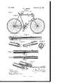
- Figure 1 is a view in side elevation of a bicycle constructed in accordance with my invention.
- Fig. 2 is a vertical sectional view through the top bar, the upper end of the seat-post being shown in elevation.
- Fig. 3 is a detail perspective view of the meeting ends of the two parts of the separable top bar detached from each other.
- Fig. 4 is a sectional view on the line 44 of Fig. 2.
- Fig. 5 is a fragmentary detail view of the meeting ends of the two parts of the front brace secured together.
- Fig. 6 is a vertical sectional view through the same, and
- Fig. 7 is a fragmentary detail view illustrating the two parts separated.
- section B is reinforced by an interior short tube or thimble O, longitudinally slotted at G and extending from the meeting end rearwardly for some distance, being secured to the section B by means of a rivet O
- the section B consists of a single tube for the greater part of its length, but provided at its meeting end with. a reinforcing inner sleeve D, in which is fitted a tube D of any proper size to snugly fit within the sleeve 0 in the end B, and provided with a pin D to enter the longitudinal slot 0, that portion of the tube D between the pin D and the end of the section B.
- This brace is composed of two sections II and H, which are tubular for the greater part of their length, but formed solid for a sufficient length at their meeting ends to make a rigid joint.
- the section H is provided with a semicylindrical solid end I and the section H with a similar semicylindrical solid end '1, these ends, when brought together, forming a halved lap-joint.
- the end I is provided on its fiat inner face with projections J and theend I with recesses J, into which said projections enter when the two ends are brought together.
- a thumbscrew K is threaded into openings L and L in the solid ends I and I to hold the parts rigidly together. 7
- the bicycle is set up for use, as in Fig. 1, the pin D of sectionB of the top bar stands at about the angle illustrated in Fig.
- the top bar A consisting of two separable sections, the section B being provided at its meeting end with an inner reinforcing-sleeve 0 having a slot G, and the section B being provided with a projecting tube D of the size to fit within the sleeve 0, and a pin D projecting laterally from the tube D to engage in the slot 0 when the tube D is placed in the sleeve C, in combination with the front brace E made in two sections, provided with a joint adapted to come together laterally and fastening means for said joint, the pin D being placed at a proper angle to cause it to look behind the inner edge of the sleeve 0 when the two sections of the front brace E are brought together, substantially as described.
- a telescoping joint consisting of a frame-bar in separable sect-ions, the one section being provided at its meeting end with the inner reinforcing-sleeve having a slot, and the other section being provided with a projecting tube of the size to lit within the said sleeve, and a pin projecting laterally from the said tube to engage in the said slot when the tube is placed in the sleeve to pass beyond the end of said slot and to turn in the frame-section to prevent endwise displacement.
Landscapes
- Engineering & Computer Science (AREA)
- Mechanical Engineering (AREA)
- Mutual Connection Of Rods And Tubes (AREA)
Description
Nu. amass.
Patented Jan. l0, I899. W. L. MARTIN.
BICYCLE.
(Application filed June 11, 1898.) (No Model.)
/ tum ago THE mmms PYERS m. PHOTO-LII'NQ, wan (to UNITED STATES PATENT" OFFICE.
WILLIAM L. MARTIN, OF RANGOCAS, NEIV JERSEY.
BICYCLE.
SPECIFICATION forming part of Letters Patent No. 617,536, dated January 10, 1899.
Application filed June 11, 1898. Serial N0. 633,224. (No model.)
To all whom it may concern:
Be it known that 1, WILLIAM L. MARTIN, a citizen of the United States, residing at Rancocas, in the county of Burlington and State of New Jersey, have invented a new and useful Bicycle, of which the followingis a specification. I
This invention relates to bicycles, the object being to construct the bicycle-frame so that the portions thereof carrying the front wheel and the rear wheel and driving mechanism may be separated for the purpose of packing the bicycle for storage or transportation.
'With this object in View the invention consists of a frame the top bar and front brace of which are made in sections, the improved construction, arrangement, and combination of the parts thereof being fully described hereinafter and afterward specifically pointed out in the claims.
In order to enable others skilled in the art to which my invention most nearly appertains to make and use the same, I will now proceed to describe its construction and operation, having reference to the accompanying drawings, in which Figure 1 is a view in side elevation of a bicycle constructed in accordance with my invention. Fig. 2 is a vertical sectional view through the top bar, the upper end of the seat-post being shown in elevation. Fig. 3 is a detail perspective view of the meeting ends of the two parts of the separable top bar detached from each other. Fig. 4 is a sectional view on the line 44 of Fig. 2. Fig. 5 is a fragmentary detail view of the meeting ends of the two parts of the front brace secured together. Fig. 6 is a vertical sectional view through the same, and Fig. 7 is a fragmentary detail view illustrating the two parts separated.
Like letters of reference indicate the same parts in all the figures of the drawings.
portion of the bicycle-frame which carries front wheel and steering mechanism. The
section B is reinforced by an interior short tube or thimble O, longitudinally slotted at G and extending from the meeting end rearwardly for some distance, being secured to the section B by means of a rivet O The section B consists of a single tube for the greater part of its length, but provided at its meeting end with. a reinforcing inner sleeve D, in which is fitted a tube D of any proper size to snugly fit within the sleeve 0 in the end B, and provided with a pin D to enter the longitudinal slot 0, that portion of the tube D between the pin D and the end of the section B. and sleeve D being slightly longer than the length of the inner slotted sleeve 0 of the section B, so that when the tube D is inserted far enough into the section B to bring the meeting ends of that seetion'and the section B together the pin D will have passed beyond the inner end of the sleeve 0 and may be turned 'to engage behind the inner end of the sleeve and prevent the two sections from being pulled apart, as best shown in Fig. 4. The section B, sleeve D, and tube D" are secured together by rivets D E indicates the front brace, which, as is usual,connects the crank-hanger F with the steering-post G. This brace is composed of two sections II and H, which are tubular for the greater part of their length, but formed solid for a sufficient length at their meeting ends to make a rigid joint. The section H is provided with a semicylindrical solid end I and the section H with a similar semicylindrical solid end '1, these ends, when brought together, forming a halved lap-joint. The end I is provided on its fiat inner face with projections J and theend I with recesses J, into which said projections enter when the two ends are brought together. A thumbscrew K is threaded into openings L and L in the solid ends I and I to hold the parts rigidly together. 7
WVhen the bicycle is set up for use, as in Fig. 1, the pin D of sectionB of the top bar stands at about the angle illustrated in Fig.
4:, being turned out of line with the slot C and engaging behind the inner end of the sleeve 0. In order to separate the two parts of the bicycle, it will be necessary to turn the section B to bring the pin D in line with the slot 0, so that the tube D may he slipped out of the sleeve 0. This cannot be accomplished while the two sections of the front brace E are secured together. Therefore in order to separate the front and rear portions of the frame the thumb-screw K must be turned out sufficiently far to disengage itself from the opening L in the solid end .I of the section II, which will permit of the turning of the whole front portion of the frame, including the section. B of the top part, bringing the pin D into line with the slot C, so that the tube may be withdrawn out of the section B, leaving the front part of the frame separate from the rear part, so that they may be packed into a smaller compass than when secured together.
To set up the bicycle for use again, the operation of separating the parts, as before described, is reversed,the tube D being inserted in the sleeve C, with the pin D in the slot 0, and pressed inward until the pin D passes beyond the inner end of the sleeve 0, as before described, when the section B is turned, locking the pin D behind the inner end of the sleeve 0 and bringing the sections H and II of the front brace E together, to be secured by turning in the thumb-screw K.
From the foregoing it will be seen that I have produced a very cheap and simple bicycle-frame which may be quickly and readily separated into two parts, whereby it may be closely packed for storage or transportation,
taking much less room than a non-separable frame.
Having thus fully described my invention, what I claim as new, and desire to secure by Letters Patent of the United States, is-
1. In a bicycle, the top bar A consisting of two separable sections, the section B being provided at its meeting end with an inner reinforcing-sleeve 0 having a slot G, and the section B being provided with a projecting tube D of the size to fit within the sleeve 0, and a pin D projecting laterally from the tube D to engage in the slot 0 when the tube D is placed in the sleeve C, in combination with the front brace E made in two sections, provided with a joint adapted to come together laterally and fastening means for said joint, the pin D being placed at a proper angle to cause it to look behind the inner edge of the sleeve 0 when the two sections of the front brace E are brought together, substantially as described.
2. In a bicycle, a telescoping joint consisting of a frame-bar in separable sect-ions, the one section being provided at its meeting end with the inner reinforcing-sleeve having a slot, and the other section being provided with a projecting tube of the size to lit within the said sleeve, and a pin projecting laterally from the said tube to engage in the said slot when the tube is placed in the sleeve to pass beyond the end of said slot and to turn in the frame-section to prevent endwise displacement.
WILLIAM L. MARTIN. \Vitnesses:
EDWIN F. MANUEL, WILLIAM T. SMITH.
Publications (1)
| Publication Number | Publication Date |
|---|---|
| US617536A true US617536A (en) | 1899-01-10 |
Family
ID=2686145
Family Applications (1)
| Application Number | Title | Priority Date | Filing Date |
|---|---|---|---|
| US617536D Expired - Lifetime US617536A (en) | Bicycle |
Country Status (1)
| Country | Link |
|---|---|
| US (1) | US617536A (en) |
Cited By (8)
| Publication number | Priority date | Publication date | Assignee | Title |
|---|---|---|---|---|
| US4344718A (en) * | 1981-11-02 | 1982-08-17 | Atlantic Richfield Company | Cold weather coupling device |
| US5269550A (en) * | 1991-02-01 | 1993-12-14 | Dahon California, Inc. | Mountain bike |
| US5852949A (en) * | 1996-07-30 | 1998-12-29 | Thermo Fibertek Inc. | Segmented screw traversing mechanism |
| US20040245743A1 (en) * | 2003-06-04 | 2004-12-09 | Hung-Chang Chao | Portable bicycle |
| WO2005084338A3 (en) * | 2004-03-01 | 2005-12-08 | Errol Drew | An interlocking separable joint |
| WO2011026459A1 (en) * | 2009-08-22 | 2011-03-10 | Europrotec Gmbh | Dismountable bicycle |
| WO2011067742A1 (en) * | 2009-12-06 | 2011-06-09 | Tsafrir Bashan | Recyclable cardboard bicycle |
| US12529470B1 (en) * | 2025-01-21 | 2026-01-20 | Linhai Shunsheng Decorative Lighting Co., Ltd | Portable and spliced lamp stand |
-
0
- US US617536D patent/US617536A/en not_active Expired - Lifetime
Cited By (12)
| Publication number | Priority date | Publication date | Assignee | Title |
|---|---|---|---|---|
| US4344718A (en) * | 1981-11-02 | 1982-08-17 | Atlantic Richfield Company | Cold weather coupling device |
| US5269550A (en) * | 1991-02-01 | 1993-12-14 | Dahon California, Inc. | Mountain bike |
| US5852949A (en) * | 1996-07-30 | 1998-12-29 | Thermo Fibertek Inc. | Segmented screw traversing mechanism |
| US20040245743A1 (en) * | 2003-06-04 | 2004-12-09 | Hung-Chang Chao | Portable bicycle |
| US7080847B2 (en) * | 2003-06-04 | 2006-07-25 | Hung-Chang Chao | Portable bicycle |
| WO2005084338A3 (en) * | 2004-03-01 | 2005-12-08 | Errol Drew | An interlocking separable joint |
| US20080063469A1 (en) * | 2004-03-01 | 2008-03-13 | Errol Drew | Interlocking Separable Joint |
| WO2011026459A1 (en) * | 2009-08-22 | 2011-03-10 | Europrotec Gmbh | Dismountable bicycle |
| WO2011067742A1 (en) * | 2009-12-06 | 2011-06-09 | Tsafrir Bashan | Recyclable cardboard bicycle |
| JP2013527066A (en) * | 2009-12-06 | 2013-06-27 | バスハン,ツァフリア | Recyclable cardboard motorcycle |
| US8662513B2 (en) | 2009-12-06 | 2014-03-04 | I.G. Cardboard Technologies Ltd. | Recyclable cardboard bicycle |
| US12529470B1 (en) * | 2025-01-21 | 2026-01-20 | Linhai Shunsheng Decorative Lighting Co., Ltd | Portable and spliced lamp stand |
Similar Documents
| Publication | Publication Date | Title |
|---|---|---|
| US617536A (en) | Bicycle | |
| US596998A (en) | Territory | |
| US508418A (en) | Umbrella-support for bicycles | |
| US638112A (en) | Bicycle. | |
| US577673A (en) | Charles e | |
| US561665A (en) | Folding bicycle-frame | |
| US469592A (en) | parkes | |
| US625612A (en) | Convertible bicycle | |
| US567159A (en) | Almy le grand peirce | |
| US337404A (en) | Circle-iron for wagons | |
| US612989A (en) | Adjustable bicycle-han ole | |
| US597801A (en) | Edward spencer hall | |
| US619646A (en) | Bicycle-support | |
| US617535A (en) | Bicycle | |
| US592886A (en) | Convertible package-carrying bicycle | |
| US620834A (en) | Henry belcher and frederick easom | |
| US650393A (en) | Bicycle seat-post. | |
| US607543A (en) | Adjustable handle-bar | |
| US599152A (en) | schluer | |
| US518330A (en) | Necticut | |
| US578921A (en) | Feed e | |
| US360009A (en) | Tongue for vehicles | |
| US322543A (en) | John knous | |
| US574734A (en) | Ferdinand f | |
| US585054A (en) | William h |