CN1064911C - Driving force auxiliary device - Google Patents
Driving force auxiliary device Download PDFInfo
- Publication number
- CN1064911C CN1064911C CN961902272A CN96190227A CN1064911C CN 1064911 C CN1064911 C CN 1064911C CN 961902272 A CN961902272 A CN 961902272A CN 96190227 A CN96190227 A CN 96190227A CN 1064911 C CN1064911 C CN 1064911C
- Authority
- CN
- China
- Prior art keywords
- rotor
- propulsive effort
- motor
- housing
- auxiliary device
- Prior art date
- Legal status (The legal status is an assumption and is not a legal conclusion. Google has not performed a legal analysis and makes no representation as to the accuracy of the status listed.)
- Expired - Fee Related
Links
Images


Classifications
-
- B—PERFORMING OPERATIONS; TRANSPORTING
- B62—LAND VEHICLES FOR TRAVELLING OTHERWISE THAN ON RAILS
- B62M—RIDER PROPULSION OF WHEELED VEHICLES OR SLEDGES; POWERED PROPULSION OF SLEDGES OR SINGLE-TRACK CYCLES; TRANSMISSIONS SPECIALLY ADAPTED FOR SUCH VEHICLES
- B62M6/00—Rider propulsion of wheeled vehicles with additional source of power, e.g. combustion engine or electric motor
- B62M6/40—Rider propelled cycles with auxiliary electric motor
- B62M6/55—Rider propelled cycles with auxiliary electric motor power-driven at crank shafts parts
Landscapes
- Engineering & Computer Science (AREA)
- Chemical & Material Sciences (AREA)
- Combustion & Propulsion (AREA)
- Transportation (AREA)
- Mechanical Engineering (AREA)
- Electric Propulsion And Braking For Vehicles (AREA)
- Connection Of Motors, Electrical Generators, Mechanical Devices, And The Like (AREA)
- Handcart (AREA)
- Automatic Cycles, And Cycles In General (AREA)
Abstract
A driving force auxiliary device for combining human power driving force and motor driving force comprises a human power driving means, an auxiliary driving means and a pedaling force detecting means, wherein the human power driving force means transmits human power driving force to an output gear 17 via a first one-way clutch and a resilient body 16 for transmitting rotating force which are both provided on a crank shaft, wherein motor driving force of the auxiliary driving force means is combined with the human power driving force on the external circumference of the crank shaft via a second one-way clutch and wherein the pedaling force detecting means 30 comprises first and second rotating members 31, 32 sandwiching the resilient body 16, a pair of bevel gears 33, 34 adapted to engage the first and second rotating members 31, 32, respectively, a bevel gear 35 mounted between the bevel gears 33, 34 in mesh engagement therewith, an output shaft 37 perpendicular to a supporting shaft 36 secured to the output shaft 37 for supporting the bevel gear 35, and a sensor 38 connected to the output shaft 37, whereby it is possible to obtain a small-size driving force auxiliary device.
Description
Technical field
The present invention relates to the light-duty vehicle of bicycle for example etc. and canoe etc. employed, alleviate the propulsive effort auxiliary device that pedal force and so on human load is used, relate in particular to the miniaturization that realizes this device.
Background technology
In the last few years, as the auxiliary usefulness of manpower, used the Electrical Bicycle of electro-motor to receive publicity.This kind Electrical Bicycle is the battery supply portion of loading electro-motor and powering to this motor on general bicycle, presses the motor auxiliary power of the propulsive effort supplementary provisions of manpower, to alleviate human load.In addition, the auxiliary driving force that this motor provides can not surpass the manpower propulsive effort, and control, so that moving velocity is per hour below 15 kilometers the time, carry out 100% auxiliary, when surpassing this per hour 15 kilometers the time, reduce gradually, when per hour reaching more than 24 kilometers, the auxiliary of motor is stopped.
Aforesaid Electrical Bicycle is to be provided with front-wheel 4 and trailing wheel 5 with the front and back at the vehicle frame of Electrical Bicycle 1 as shown in figure 17, and utilizes ordinary bicycle that pedal force drives trailing wheel 5 to constitute for the basis.Because in the JIS standard, the person in charge that calls shown in the symbol in the vehicle frame 2, the standpipe that calls shown in 3, so also use this title in this manual by the JIS standard.
Above-mentioned propulsive effort auxiliary device 6 comprises: with the axletree quadrature and be configured near the substantial middle of width over sides of car body direction electro-motor M, the rotating drive force transformation of this motor is become the rotation direction of axletree and the conversion speed reduction gearing (having omitted diagram) that makes it to slow down, make the motor driven power combination mechanism (having omitted diagram) synthetic with the common drive system of manpower and when being driven by manpower separately motor-driven system is separated with common drive system after this deceleration.
Motor-driven system carries out rotating drive by the torque transfer that with the electro-motor is drive source, and this electro-motor is by the electric powerplant supply capability.That is, this electric powerplant comprises: use the motor drive circuit of the battery feed portion of a plurality of storage batterys, the electro-motor that makes the power circuit part that electrical power stabilization ground supplies with, the usefulness of travelling, this revolution of direct control and to the control circuit of this motor drive circuit output speed instruction etc.The motor driven that is produced by this motor is tried hard to pursue and is added to traditional torque transfer, and passes to the wheel that travels by this transfer device, makes bicycle running.
In addition, as the method that detects this kind manpower propulsive effort, known have a kind of antagonistic force that gear is applied according to planetary wheel to detect the method for the size of manpower propulsive effort (for example Japanese patent of invention discloses 1992 No. 358987).
Yet, generally speaking, the width of the relative working direction of bicycle about it is limited, therefore, the traditional electro-motor that has longer size at length direction must be along the fore-and-aft direction configuration of car body, so must be transformed into the rotating shaft towards the car body fore-and-aft direction towards the direction of the bent axle of left and right directions.Therefore mapping device is set, speed reduction gearing etc. complicate, and the tendency of maximization is arranged simultaneously.
In addition, the propulsive effort of manpower is shown as above-mentioned traditional method of reversing and this being detected of axle, because the torsional deflection amount that moment of torsion causes is very small, so in order to have guaranteed sufficient mensuration precision, at the length direction of axle to a certain degree length must be arranged, so the tendency of maximization is arranged, not welcome.
Also have, above-mentioned traditional method, above-mentioned detection is carried out at the manpower propulsive effort place of applying, so must make the structure that can bear this very big manpower propulsive effort, device proper can tend to unfavorable condition large-scale and the weight weightening finish.
In addition, when the pedal force detecting device of detection manpower propulsive effort is exposed to the car body outside, understand damaged,, also can cause fault to cause reliability decrease because of being subjected to clashing even be without damage because of toppling over of car body.Owing to can directly be subjected to the influence of outside natural environments such as wind and rain, the thing of destruction reliability such as flase drop survey and the decline of device lifetime so might take place in the sand dust that produces when reaching vehicle ' and the influence of earth again.If can pack the pedal force detecting device in the housing into, then the problems referred to above can not take place, but if will be configured near the interior bent axle of housing, then must realize miniaturization, and there is the accuracy of detection that is difficult to both guarantee necessity in the pedal force detecting device, realizes the problem of miniaturization again.
Therefore, the objective of the invention is to, following a kind of propulsive effort auxiliary device is provided, this device can be packed small-sized weight-saving motor and bent axle in the housing of one abreast, suitably the configuration speed reduction gearing is realized the single-piece miniaturization, simultaneously by the pedal force detecting device is fitted in the transmission mechanism of propulsive effort, make the miniaturization of pedal force detecting device, in the housing of can packing into.
Disclosure of an invention
The described invention of claim 1 of the present invention, it is a kind of propulsive effort auxiliary device, it has: the Manpower driver that is provided with the bent axle that is passed to pedal force, be provided with the auxiliary power actuating device of motor and speed reduction gearing, the combination mechanism that the manpower propulsive effort that described motor driven power and described pedal force are caused is combined to, and the pedal force detecting device, it is characterized in that
Described Manpower driver has: coaxial shape is configured in the periphery of described bent axle, have the 1st free-wheel clutch, only be delivered to the 1st rotor of the suitable direction turning effort of described bent axle, be configured in the 2nd rotor of described bent axle periphery coaxial shape easy fit, be installed between described the 1st rotor and the 2nd rotor, the turning effort of described the 1st rotor is passed to the elastic body of the 2nd rotor, and the output gear that is delivered to the turning effort of described the 2nd rotor;
Described auxiliary power actuating device, the axle and the described bent axle configured in parallel of its motor and speed reduction gearing, and will from the propulsive effort of described motor through the 2nd free-wheel clutch after, synthesize propulsive effort transmission mechanism in described bent axle periphery in described Manpower driver,
Described pedal force detecting device detects and is arranged near the 1st and the 2nd rotor the difference in rotation that is installed in the 1st and the 2nd rotor before and after the described elastomeric propulsive effort bang path with sensor;
And the motor drive circuit that drives described motor is configured near this motor and in the outside of described speed reduction gearing, this motor drive circuit and described each Poewr transmission mechanism are enclosed in the housing.
The described propulsive effort auxiliary device of the application's claim 2 is in described claim 1, and the speed reduction gearing of described auxiliary power actuating device is with the reducing gear configuration of staggering mutually.
The described propulsive effort auxiliary device of the application's claim 3 is in described claim 2, the center configuration of each gear of described reduction gear train in the external diameter of the imaginary line that connects described motor and bent axle and motor in the imaginary quadrangle on each bar limit.
The described propulsive effort auxiliary device of the application's claim 4, be in described claim 1, described pedal force detecting device is provided with differential gear train, is connecting the described the 1st and the 2nd rotor on two axles of this differential gear train, and the 3rd of this differential gear train is connected with sensor.
The described propulsive effort auxiliary device of the application's claim 5, be in described claim 4, between the described differential gear train and a side or the both sides of described differential gear train between the described sensor, additional have a mechanism that makes the rotary machine amplification at the described the 1st and the 2nd rotor.
The described propulsive effort auxiliary device of the application's claim 6 is in described claim 4, and described differential gear train adopts planetary wheel.
The described propulsive effort auxiliary device of the application's claim 7, be in described claim 1, its sensor of described pedal force detecting device adopts coder, with this coder to the described the 1st and the rotating speed of the 2nd rotor count, according to this count difference judgement manpower torque.
The described invention of claim 8 of the present invention, it is a kind of propulsive effort auxiliary device, it has: the Manpower driver that is provided with the bent axle that is passed to pedal force, be provided with the auxiliary power actuating device of motor and speed reduction gearing, the combination mechanism that the manpower propulsive effort that described motor driven power and described pedal force are caused is combined to, and the pedal force detecting device, it is characterized in that
Described Manpower driver comprises:
Be configured in coaxial shape described bent axle periphery, have the 1st free-wheel clutch, only be delivered to the 1st rotor of the suitable direction turning effort of described bent axle,
Be configured in the 2nd rotor of described bent axle periphery coaxial shape easy fit,
Be installed between described the 1st rotor and the 2nd rotor, the turning effort of described the 1st rotor passed to the elastic body of the 2nd rotor,
Be delivered to the output gear of the turning effort of described the 2nd rotor;
Described auxiliary power actuating device comprises:
Motor,
Make the reduction gear train of the propulsive effort deceleration of described motor,
Be disposed at the periphery of described bent axle coaxial shape easy fit, with the final gear mesh of outer peripheral teeth and described reducing gear and have the 2nd free-wheel clutch interior week, only the suitable direction turning effort of described final gear passed to the 3rd rotor of described the 2nd rotor;
Described pedal force detecting device comprises:
Be fixed on the 1st revolving member of described the 1st rotor periphery,
Be fixed on the 2nd revolving member of described the 2nd rotor periphery,
Respectively with the described the 1st and the 2nd revolving member bonded assembly a pair of the 1st and the 2nd bevel gear,
Engagement is installed in the 3rd bevel gear between the described a pair of the 1st and the 2nd bevel gear,
The bolster of pivot Zhi Suoshu the 3rd bevel gear, change output shaft for the rotation of the described a pair of the 1st and the 2nd bevel gear as the mutual differential taking-up of the 1st and the 2nd bevel gear,
Be connected the sensor on the described output shaft.
The described propulsive effort auxiliary device of the application's claim 9 is in described claim 8, on the arbitrary device among Manpower driver, auxiliary power actuating device and the pedal force detecting device, is provided with speed detector.
The described propulsive effort auxiliary device of the application's claim 10 is in described claim 1 or 8, and described Manpower driver, auxiliary power actuating device and pedal force detecting device are housed in the housing.
The described propulsive effort auxiliary device of the application's claim 11 is in described claim 10, on described housing, is provided with the fin along working direction.
The described propulsive effort auxiliary device of the application's claim 12 is that described elastic body is a torsion-coil spring in described claim 1 or 8.
The described propulsive effort auxiliary device of the application's claim 13 is that described elastic body is a torsion-coil spring in described claim 1 or 8, and this helical spring end face forms the fillet shape, and is provided with the parts of restriction coil spring distortion.
The described propulsive effort auxiliary device of the application's claim 14 is in described claim 13, and the position of accepting described coil spring end face is arranged at the described the 1st and the 2nd rotor respectively, and curve form is arranged at the position of described receiving auger spring end face.
The described propulsive effort auxiliary device of the application's claim 15, be in described claim 13, the windup-degree of described torsion-coil spring are below 20 degree, be preferably in below 10 degree, in case surpass these windup-degree, then be located at respectively the described the 1st and the sidepiece of the extension of the 2nd rotor can be mutually against.
The described propulsive effort auxiliary device of the application's claim 16, be in described claim 1 or 8, the motor of described auxiliary power actuating device and described pedal force detecting device are configured in a side, and the train of gears of described auxiliary power actuating device is configured in opposite side.
The described propulsive effort auxiliary device of the application's claim 17 is in described claim 1 or 8, the motor of described auxiliary power actuating device, and housing is fixed in the end of the radiation direction of the magnetic pole of its stator core.
The described propulsive effort auxiliary device of the application's claim 18 is in described claim 1 or 8, and the sensor configuration of described pedal force detecting device is the described the 1st and the periphery of the 2nd rotor.
The described propulsive effort auxiliary device of the application's claim 19 is in described claim 10, and described housing is that the above housing parts of at least 3 parts is combined into one and form.
The described propulsive effort auxiliary device of the application's claim 20 is in described claim 10, and the maximum width of described housing is set at the interval less than the Regular Bicycle pedal arm.
The described propulsive effort auxiliary device of the application's claim 21 is in described claim 10, is formed with a distribution conveying end on the described housing, and the distribution of described motor and sensor is drawn from described distribution conveying end.
The described propulsive effort auxiliary device of the application's claim 22, be in described claim 10, be connected with the circuit substrate of motor drive circuit and control setup with the distribution of adaptor union, described circuit substrate be connected with power supply unit with adaptor union with described motor and sensor.
The described propulsive effort auxiliary device of the application's claim 23, be in described claim 10, the circuit substrate of described motor, described sensor and control setup is configured within the housing, and their distribution is connected in the power supply unit that is configured in outside the housing by adaptor union.
The described propulsive effort auxiliary device of the application's claim 24, be in described claim 23, described power supply unit is disposed at the person in charge, and, described motor and described power supply unit relatively are disposed at described housing, and the distribution of described circuit substrate is connected in described power supply unit by adaptor union.
The described propulsive effort auxiliary device of the application's claim 25, be in described claim 23, described power supply unit is disposed at standpipe, and, described motor and described power supply unit relatively are disposed at described housing, and the distribution of described circuit substrate is connected in described power supply unit by adaptor union.
The described propulsive effort auxiliary device of the application's claim 26 is in described claim 10, and the circuit substrate of described motor and control setup is disposed at the front of working direction side, top or back when housing is provided with.
The described propulsive effort auxiliary device of the application's claim 27 is in described claim 10, and the circuit substrate of described motor drive circuit and control setup is disposed near the speed reduction gearing sidepiece the described motor.
The described propulsive effort auxiliary device of the application's claim 28 is in described claim 27, is being formed with peristome in the face of on the housing of described circuit substrate, and disposes adaptor union on described circuit substrate, and described adaptor union is facing to described peristome setting.
The described propulsive effort auxiliary device of the application's claim 29 is in described claim 10, and power configuration person in charge Yu is connected with the circuit substrate of the adaptor union above the housing of being located at working direction side the place ahead or the housing with described power supply and control setup.
Of the present invention with manpower propulsive effort and the synthetic propulsive effort auxiliary device of motor driven power, have Manpower driver, auxiliary power actuating device and pedal force detecting device, when make bent axle when rotating with pedal force along direction, this turning effort passes to output gear by above-mentioned the 1st free-wheel clutch and above-mentioned elastic body.
Unidirectional in addition, the motor driven power of above-mentioned auxiliary power actuating device, is synthesized in above-mentioned Manpower driver in above-mentioned bent axle periphery by the 2nd free-wheel clutch, passes to above-mentioned output gear again.
In addition, the reciprocal rotation of above-mentioned bent axle is owing to above-mentioned the 1st free-wheel clutch dallies.Similarly, the rotation of general above-mentioned Manpower driver can not pass to motor one side owing to above-mentioned the 2nd free-wheel clutch.Above-mentioned pedal force detecting device is the device that utilizes sensor that the difference in rotation that is installed in the 1st and the 2nd rotor before and after the above-mentioned elastomeric propulsive effort bang path is detected, for example differential gear train is set and constitutes, make the above-mentioned the 1st to be connected with two axles of this differential gear train, and make the 3rd of this differential gear train to be connected with sensor with the 2nd rotor.Therefore, in case pedal force makes bent axle to rotating along direction, the above-mentioned the 1st and the 2nd rotor that is configured in front and back, above-mentioned the 1st free-wheel clutch path promptly rotates, and the bevel gear of the differential gear train that is attached thereto or planetary wheel also rotate respectively.Because when pedal force is big, elastic deformation can take place in above-mentioned elastic body, so the poor of advance angle can be taken place between the two at the above-mentioned the 1st and the 2nd rotor.Because above-mentioned differential gear train is meshing bevel gear or planetary wheel, be the angle of output shaft again so the difference of above-mentioned advance angle is transformed into the 3rd of this differential gear train.The angle variation of this output shaft is detected by the sensor that is connected in this output shaft, can measure the size of above-mentioned pedal force thus, and feed back to the motor driven power of above-mentioned auxiliary power actuating device.
As mentioned above, if adopt propulsive effort auxiliary device of the present invention, then because each component part configuration is reasonable, so can be housed in small-sized weight-saving motor and bent axle abreast in the housing of one, by suitably disposing speed reduction gearing, realize the single-piece miniaturization, and the pedal force detecting device is assembled in the transmission mechanism of propulsive effort again, therefore, the pedal force detecting device can be realized miniaturization and take within the housing.
Brief description:
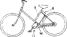
Fig. 1 is the lateral plan that whole schematic configuration is shown for using the Electrical Bicycle of power unit of the present invention.
Fig. 2 is the sectional elevation that power unit of the present invention is shown.
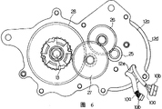
Fig. 3 shows power unit of the present invention, is to unload the birds-eye view that illustrates after the lower house part.
Fig. 4 shows power unit of the present invention, is to unload the front view that illustrates after the lower house part.
Fig. 5 shows power unit of the present invention, is to unload the back view that illustrates after the lower house part.
Fig. 6 shows power unit of the present invention, is to unload the back view that illustrates after the lower house part.
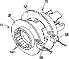
Fig. 7 is with used in the power unit of the present invention, the 1st rotor, elastic body with the block diagram that illustrates after the 2nd rotor separates.
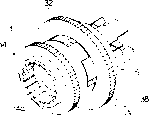
Fig. 8 is the assembling stereogram that used in the power unit of the present invention, the 1st rotor and the 2nd rotor are shown.
Fig. 9 is the front view that the used pedal force detecting device of power unit of the present invention is shown.
Figure 10 is the upward view that the used pedal force detecting device of power unit of the present invention is shown.
Figure 11 is the right elevation that the used pedal force detecting device of power unit of the present invention is shown.
Figure 12 is the block diagram that other embodiment of the used pedal force detecting device of power unit of the present invention are shown.
Figure 13 is the block diagram that the used speed detector of power unit of the present invention is shown.
Figure 14 shows that the Electrical Bicycle that uses power unit of the present invention, is the lateral plan that whole schematic configuration is shown.
Figure 15 is the front view that is provided with the state of power unit of the present invention in Electrical Bicycle.
Figure 16 is the front view that is provided with the state of power unit of the present invention in Electrical Bicycle.
Figure 17 is the whole summary pie graph that the conventional electric bicycle is shown.
The optimal morphology that carries out an invention
Followingly the present invention is illustrated to each embodiment shown in Figure 16 according to Fig. 1.
Shown in Figure 14 shown in Fig. 1 and back, as the manually driven light-duty vehicle of each embodiment, what illustrate is to use occasion in bicycle.Again, the basic structure of the bicycle shown in is also identical among described in the back each embodiment here.
In the present embodiment, Electrical Bicycle 1 is the same with traditional bicycle, has set up wheel 4,5 in the front and back of vehicle frame.Vehicle frame constitutes by the person in charge 2 of front forked frame side and from being responsible for 2 standpipe 3 grades that upwards are provided with, and in the upper end of standpipe 3, is provided with the saddle that the user seat usefulness.In addition, the downside being responsible for 2 is equipped with the power unit 11 that is provided with bent axle 13, on the top of the pedal arm 7a that is installed on this bent axle 13, and articulated pedal 7.At the person in charge 2 downside and in the place ahead of power unit 11, battery cell 8 is installed equally.
Also have, in this power unit 11, electro-motor, reductor, manpower/motor driven power combination mechanism and pedal force detecting device are housed, the bent axle 13 that is connecting pedal 7 is connected with combination mechanism, the output of this combination mechanism is connected with output gear (being former movable sprocket in the present embodiment) 17, simultaneously, this former movable sprocket and with trailing wheel 5 co-axially fixed driven sprockets (not shown) between, be connected by being located at this chain 9 between the two.In addition, comprise that also some omissions are not shown, for example be located at lamp that brake lever, braking mechanism, night running on the handle use or the like, use the device identical basically with traditional bicycle.
In addition, this front-wheel 4 comes steering by the handle of being located on the front forked frame, and on the other hand, if user's pushes pedals 7, promptly the same with ordinary bicycle, the trailing wheel 5 of Electrical Bicycle utilizes manpower to travel.That is, in case by the user with manpower pushes pedals 7, i.e. the former movable sprocket of rotating drive, the propulsive effort of this former movable sprocket passes to the driven sprocket of trailing wheel through chain, trailing wheel 5 is rotated driving, so Electrical Bicycle advances.
In above-mentioned battery cell 8, be incorporated with the major key switch that makes Electrical Bicycle begin to move, a plurality of storage batterys etc. and accessory circuit etc.
For example the 24V that uses of motor is such for above-mentioned storage battery, the voltage that can obtain to stipulate.In addition, the electricity sent of this storage battery is supplied to the various device of motor and sensor and each circuit etc.
In addition, motor drive circuit is to be that the MOS-FET circuit serves as main to constitute with the on-off element that electric power is used, and by high speed switch action the carrying out copped wave control of this FET circuit, makes being supplied to the available voltage that travels with motor to increase or reduce the output of control motor.Again, the execution of this switch control is according to carrying out from the instruction of the control circuit that determines by detected manpower and moving velocity.
This control circuit is made of microcomputer, and the input of this microcomputer is from the sensor signal of the pedal force detecting device of power unit 11 and moving velocity sensor, external environment condition sensor etc., and to motor drive circuit output control signal.This microcomputer have with each incoming signal be transformed into digital signal the A/D changer, this digital signal is taken out or is read in the I/O interface of storage space and carry out predetermined process and the CPU that makes decision and memory device or the like by the data-signal that reads in from storage space.Therefore,, handle, export the suitable action command of task setting signal and so on again to motor drive circuit by the program that is stored in the memory device according to the detection signal of various sensor outputs.
Therefore, in case the closed major key switch of user is promptly powered to each relevant devices from battery cell 8, can utilize electro-motor to carry out the assistive drive of manpower.Promptly, as if user's pushes pedals 7, therewith correspondingly, the pedal force detecting device promptly detects the propulsive effort of manpower at this state, speed sensor detects moving velocity simultaneously, and control circuit is exported suitable action command according to their detection signal to motor drive circuit.According to this action command, motor drive circuit increases or reduce to be supplied to travel uses the driving electric of motor, adjusts the output of travelling with motor.The motor driven power of this generation is transformed into suitable torque by speed reduction gearing, and this motor driven power is appended on the manpower propulsive effort by combination mechanism, passes to trailing wheel 5, and Electrical Bicycle obtains the auxiliary of motor power, cosily to overtake.
In the present embodiment, as Fig. 2-shown in Figure 5, power unit 11 is to pack into to constitute as lower device in the housing 12 that 3 parts are put together (12a, 12b, 12c), promptly, be fixed with the bent axle 13 of pedal arm 7a, have the periphery that is configured in bent axle 13, prevent that bent axle 13 reversings from causing retreat and when motor stops, making motor-driven system idle running ratchet portion, motor driven tried hard to pursue the combination mechanism that is added on manpower, be configured in the power transfer path pedal force detecting device midway of this combination mechanism, manpower is auxiliary uses motor, and the speed reduction gearing of motor.In addition, also be provided with everywhere and can prop up the bearing of each by smooth and easy pivot rotationally, comprise from antifriction-bearing box to plain bearing.
Good and the light material of heat transmissibility such as above-mentioned housing 12 usefulness aluminium forms, and comprises the main casing 12a of the electro-motor M that directly packs into, and the housing 12b, the 12c that cover its left and right sides, and be arranged to can be airtight.When motor M moved, a large amount of heats that take place along with the action of electro-motor M were among this housing 12 effectively is discharged into air, and motor can move sustainedly and stably.Have again, be preferably in the fixed part that relative vehicle frame is set near the housing of motor.Like this, the above-mentioned heat that sends can distribute by the vehicle frame of housing to bicycle.In addition, on housing 12, be provided with radiating gill 12d, so that can improve radiating effect along working direction.
And for example shown in Figure 6, be enclosed in the motor M in the housing 12 and the feed cable and the sensor flexible cord (the following distribution 10a that only is called) of sensor and draw from the mono-peristome 12e that is located at main casing 12a.In the present embodiment, in the face of forming peristome 12e on the housing of circuit substrate 8a, on circuit substrate 8a, dispose adaptor union 10b again, and make this adaptor union 10b be faced with peristome 12e.Thus, can improve assembly performance and maintenance characteristics.Also have, because these distributions 10a can combine with other power supplys and control part by being located at the adaptor union 10b on top, so can improve assembly performance and maintenance characteristics equally.
In addition, in the present embodiment, near the motor in housing 12 and at the sidepiece of speed reduction gearing, the circuit substrate 8a of configuration motor drive circuit and control setup, and load onto case lid 12f, cover from the outside.
The propulsive effort auxiliary device of present embodiment is that power unit 11 comprises that it is the Manpower driver that former movable sprocket makes it to rotate that pushes pedals 7 makes bent axle 13 rotate and it is passed to output gear 17, the auxiliary power actuating device of the rotation of the auxiliary bent axle 13 of the driving by motor M, and the pedal force detecting device that the power of described auxiliary power actuating device is applied the usefulness of making decision.
Above-mentioned Manpower driver at first is described.
Manpower driver is to be configured in roughly bent axle 13 device on every side, be configured in the 1st rotor 14 of bent axle 13 peripheries with comprising coaxial shape, coaxial shape is configured in the 2nd rotor 15 of bent axle 13 peripheries rotationally, be contained between above-mentioned the 1st rotor 14 and the 2nd rotor 15, the turning effort of above-mentioned the 1st rotor is passed to the elastic body 16 of the 2nd rotor, and the output gear 17 that is delivered to the turning effort of above-mentioned the 2nd rotor 15.In addition, in the present embodiment, between the 2nd rotor 15 and output gear 17, be connected with barrel-contoured adaptor union 18.
Above-mentioned the 1st rotor 14 has the 1st free-wheel clutch, only transmits the turning effort of the suitable direction of above-mentioned bent axle.The 1st free-wheel clutch is provided with outwardly directed feeding pawl 13a on the one hand on bent axle 13, on the inner peripheral surface of the 1st rotor 14, carve and be provided with interior all tooth 14a that the dip plane is arranged in reverse directions on the other hand.Therefore, when bent axle 13 to along direction promptly when vehicle forward direction is rotated, the feeding pawl 13a of this bent axle 13 combines and transmission of drive force with interior all tooth 14a of the 1st rotor 14.On the other hand, when bent axle 13 when the reversing sense with motor of travelling promptly allows the direction of vehicle rollback rotate because feeding pawl 13a cross in the dip plane of all tooth 14a, both not combinations, so bent axle 13 idle running, the propulsive effort of counter-rotating does not pass to the 1st rotor 14, and trailing wheel 5 is nonreversible.
As previously mentioned, above-mentioned the 1st rotor 14 and the 2nd rotor 15 are by elastic body 16, are by the torsion-coil spring bonded assembly in the present embodiment.This torsion-coil spring uses by predetermined size and material and does curl, can guarantee that the spring constant of stipulating also produces and the spring of corner corresponding torque.
This helical spring end face 16a makes the fillet shape, and 16a is corresponding with this end face, and the position 14e and the 15e of receiving auger spring end face are arranged to curve form.Therefore, helical spring end face 16a can stablize with 15e for the position 14e that accepts this coil spring end face and contacts.
In addition, in the present embodiment, when also taking measures to make torsion-coil spring generation elastic deformation, still keep the posture of spring, limit its distortion and surpass specified amount.That is, be provided with limiting part, when torsion-coil spring is subjected to application force and when elastic deformation took place, this limiting part kept its posture and limit its distortion surpassing specified amount, so that coil spring has desirable distortion.In the present embodiment, helical spring distortion is limited the salient 14c that introduces and the interior week of 15c and the periphery of bent axle 13 by the screw-shaped groove 14b of the 1st and the 2nd rotor 14,15 inner peripheral surfaces and 15b, back.Promptly, on the axial inner end face of the 1st rotor 14 and the 2nd rotor 15, be formed with and this torsion-coil spring cooresponding screw-shaped slot part 14b and 15b, torsion-coil spring is the restriction that the sidepiece of elastic body 16 is subjected to above-mentioned screw-shaped slot part 14b, 15b, perhaps, the outer peripheral portion of elastic body 16 is subjected to the restriction in the interior week of salient 14c, 15c, and perhaps, elastomeric inside part is subjected to the restriction of the periphery of bent axle 13.
Therefore, when carrying out the back when manpower of introducing is transmitted, elastic deformation takes place on one side in this torsion-coil spring, on one side transmit the manpower propulsive effort, because coil spring or contact, perhaps with the contacting in interior week of salient 14c, 15c with screw-shaped groove 14b, 15b, perhaps the periphery with bent axle 13 contacts, so can prevent that spring to axially toppling over or abnormal deformation taking place, can keep due shape, therefore can guarantee the spring constant of stipulating.In addition, in the present embodiment, be that the end surface side of limit pushing torsion-coil spring is transmitted the manpower propulsive effort, but also can make the form that transmit on stretching limit, limit.Also have, elastic body 16 can use spring arbitrarily so long as the spring of generation and corner corresponding torque then is not limited to torsion-coil spring.
Again, in the present embodiment, the windup-degree of this torsion-coil spring are set at below 20 degree, are advisable below being preferably 10 degree, so that the user does not feel is uncomfortable.
Like this, with the driving torque that puts on the 1st rotor 14 correspondingly, the torsion-coil spring limit meets the elastic deformation of spring constant, the limit passes to the 2nd rotor 15 to propulsive effort.Its result, with this torque correspondingly, by the back pedal force detecting device of introducing 30 is detected the amount of the rotational angle of two differential rotors, can detect pedal force.That is,, be fixed with the 1st and the 2nd different revolving member 31,32 of diameter respectively, with input gear 41,42 engagements of pedal force detecting device 30 in the periphery of these the 1st and the 2nd rotors 14,15.In the present embodiment, the 1st and the 2nd revolving member the 31, the 32nd, gear.
In addition, at the relative position of the 1st and the 2nd rotor 14,15, be provided with salient 14c, 15c along peripheral shape, when pedal force diminishes elastic body 16 when not reversing, can guarantee has predetermined gap L mutually with being provided with predetermined distance.Therefore, when be subjected to that manpower etc. causes cross large driving force the time, directly butt, connection mutually between salient 14c, the 15c sidepiece is to prevent the destruction of torsion-coil spring.
As previously mentioned, the 2nd rotor 15 is connected with barrel-contoured adaptor union 18.Originally, the 2nd rotor 15 and adaptor union 18 were with different component set-ups in the present embodiment, but also can be made of one.
In addition, in the present embodiment, the 1st and the 2nd revolving member 31,32 is to use gear as shown in the figure.But the 1st and the 2nd revolving member 31,32 is not limited to gear, can use and can transmit roller of rotating and so on rotor arbitrarily.
Below above-mentioned auxiliary power actuating device is described.
This auxiliary power actuating device has: motor M, the reduction gear train that the propulsive effort of motor is slowed down, and coaxial shape is configured in the periphery of above-mentioned bent axle 13 rotationally, with the final gear mesh of its outer peripheral teeth and above-mentioned reducing gear and have the 2nd free-wheel clutch interior week, only the turning effort of the suitable direction of above-mentioned final gear passed to the 3rd rotor of above-mentioned the 2nd rotor 15.
This motor M comprises by key and is fixedly connected on rotor core 22 on the motor drive shaft 21, that have magnet, and is configured in its periphery, directly is fixed on stator core 23 on the housing 12a.As shown in Figure 4, said stator iron core 23 by the bolt parallel 24 with motor drive shaft the end of the radiation direction of the magnetic pole 23a of stator core 23 be fixed on housing in portion.Promptly, consider position by the magnetic line of force of this stator core 23, with bolt 24 the low part of the magnetic flux density of this magnetic line of force is combined with housing, thereby can be suppressed to Min. because of the bad influence that screw and bolt damage magnetic flux and so on is set, can prevent from therefore to cause the decline of motor performance.In addition, because of not needing special-purpose motor shell, so can realize miniaturization.
Above-mentioned reduction gear train constitutes by the 1st gear unit 25 on the motor drive shaft 21 that is fixed on motor M and with the 1st gear unit 26,27 of ingear the 2nd, the 3rd gear units successively, the helical wheel of each minor diameter drives with the engagement of large diameter helical wheel respectively, makes it corresponding with high speed rotating and can obtain the reduction ratio stipulated.
In the present embodiment, each gear center of above-mentioned reduction gear train be configured in the imaginary line that connects motor M and bent axle and motor external diameter be each limit, among Fig. 5 in the imaginary quadrangle shown in the long and short dash line.And, the reducing gear configuration of staggering mutually.When disposing like this, the auxiliary power actuating device can be realized miniaturization.
In addition, the 3rd rotor 28 meshes with the 3rd gear unit 27 of reducing gear, and is configured in the periphery of the 2nd rotor 15, simultaneously, carves the interior all tooth 28a that are provided with in that the dip plane is arranged along direction within it week.
In addition unidirectional, on the 2nd rotor 15, be provided with outwardly directed feeding pawl 15d, therefore, above-mentioned in all tooth 28a only be set at the 3rd rotor 28 when rotating, just combine with the feeding pawl 15d of the 2nd rotor 15 peripheries along direction.
Therefore, when bent axle 13 by manpower to drivings that rotate along direction, and because factor such as driving conditions and motor when stopping to drive, the 3rd rotor 28 dallies, the manpower propulsive effort can not be delivered to motor-driven system.
Because the above-mentioned aforesaid structure of auxiliary power actuating device, so can will be transformed into suitable torque/speed by the mechanical type speed reduction gearing by the output that electro-motor obtains, and this propulsive effort passed to combination mechanism effectively, can assist manpower to come rotating drive trailing wheel 5.
Pedal force detecting device 30 then is described in accordance with the embodiments illustrated.
In the present embodiment, pedal force detecting device 30 is to judge the manpower torque according to the difference of the rotation of the 1st and the 2nd rotor 14,15 that links to each other through above-mentioned torsion-coil spring.This pedal force detecting device 30 is extremely shown in Figure 11 as Fig. 9, basically constitute by differential gear train, connecting the above-mentioned the 1st and the 2nd rotor 14,15 on two axles of this differential gear train, the 3rd of this differential gear train the (output shaft 37) links to each other with sensor simultaneously.The differential gear train here is as the JIS prescribed by standard, when two axles are driven, the 3rd wheel word that is subjected to the effect of this diaxon simultaneously and rotates, what use is planetary gear apparatus, is purpose with differential, often center gear and planetary wheel is made bevel gear.In the present embodiment also as described later, in differential gear train, use bevel gear.
Specifically be, pedal force detecting device 30 comprises: the 1st rotor (being gear in an embodiment) 31 that is fixed on described the 1st rotor 14 peripheries, be fixed on the 2nd rotor (being gear in an embodiment) 32 of described the 2nd rotor 15 peripheries, be connected to a pair of bevel gear 33,34 of the described the 1st and the 2nd rotor, engagement is installed in a plurality of bevel gears 35,35 between the described a pair of bevel gear, fixing pivot Zhi Suoshu bevel gear bolster 36 and with the output shaft 37 of this bolster quadrature, and with these output shaft 37 bonded assembly sensors 38.
In the present embodiment, the 3rd of differential gear train is that output shaft 37 pivots prop up between the support 39,39 of making circular-arc and configuration parallel to each other, on this output shaft 37, be set with the 1st input gear 41 rotationally, and bolster 36 rotates with this output shaft 37.
The the above-mentioned the 1st and the 2nd input gear 41,42 is fixed with bevel gear 33,34 respectively, and as previously mentioned, between these bevel gears 33,34, engagement is equipped with bevel gear 35,35.
Above-mentioned the 1st revolving member 31 that the above-mentioned the 1st and the 2nd input gear 41,42 is different with diameter respectively and the 2nd revolving member 32 link to each other.Wherein, the 2nd input gear 42 directly meshes with the 2nd revolving member 32, and the 1st input gear 41 then meshes by the counter gear 43 and the 1st revolving member 31 of minor diameter.This be because, bevel gear 33,34 must be with identical rotating speed to different direction rotations, because, to make on the one hand to the 1st revolving member 31 of equidirectional rotation and any counter-rotating among the 2nd revolving member 32, on the other hand, to clamp counter gear, clamp the space that this counter gear is used so must have for making its counter-rotating, so, must make the diameter of above-mentioned the 1st revolving member 31 and the 2nd revolving member 32 inequality.
In addition, in the train of gears of above-mentioned the 1st revolving member 31 and the 2nd revolving member the 32, the 1st and the 2nd input gear 41,42 and counter gear 43, its number of teeth is that the rotating speed that is set at the 1st revolving member 31 and the 2nd revolving member 32 is exaggerated input the 1st and the 2nd input gear 41,42.Also have, output shaft 37 is by linking to each other with the detection of gear 45 of sensor 38 (being potential device in the present embodiment) by the gear 44 that amplifies rotating speed.
As mentioned above, at the 1st and the 2nd rotor 14,15 between the above-mentioned differential gear train, and the side of above-mentioned differential gear train among between the above-mentioned sensor 38, or as present embodiment both sides, add under the situation of the mechanism that mechanicalness amplification rotating speed is arranged, when being transformed into electric signal with sensor, import the absolute magnitude of this sensor bigger obtain more accurate electric signal.
Because the bevel gear 35 that engagement links to each other rotates around output shaft 37 and moves, so produce by above-mentioned torsion-coil spring, poor with the advance angle of corresponding the 1st rotor 14 of manpower level of torque and the 2nd rotor 15, make output shaft 37 rotate a corresponding rotational angle of difference with this advance angle.Promptly, when the rotating speed of the 1st rotor 14 and the 2nd rotor 15 equates, bevel gear 35 is rotated further under the situation of the angle position that keeps its output shaft, in contrast, when both rotating speeds are unequal, the opposing party is rotating relative to stopping can to regard a side as, and bevel gear 35 correspondingly rotates and moves around output shaft 37 with this difference in rotation, and the bolster 36 of bevel gear 35 rotates corresponding angle by rotating extent.This angle is amplified the gear 45 that passes to potential device by gear 44 again, and detects with potential device, just can correctly detect the driving torque of manpower.
In addition, the bevel gear that above-mentioned differential gear train can certainly be above-mentioned, and replace with planetary wheel.
In addition,, stretch out to a side and to be provided with arm member 46, connecting the end that the other end is fixed in the force application spring 47 of vehicle frame on the arm member 46 in the centre of the detection axle of potential device, and be provided with this arm member 46 against block piece 48.Therefore, the detection axle of potential device relies on a direction because of the effect of this force application spring 47 all the time, and is subjected to stopping of block piece 48, so, can guarantee to revise the zero point of potential device, and can prevent the loosening of each gear, can guarantee the accuracy of detection of sufficient manpower torque.
Below again other embodiment of pedal force detecting device are described.The pedal force detecting device uses coder in the present embodiment, and the rotating speed of the 1st rotor 14 and the 2nd rotor 15 is counted, and judges the manpower torque according to the difference of this counting.
Specifically be as shown in figure 12, periphery at the 1st rotor 14 and the 2nd rotor 15, week shape be provided with the discoid detection plectane (the 1st and the 2nd revolving member 31,32) of narrow slit with regulation, and have and clip the rotation detecting sensor 38 that respectively detects the optical chopper formula plectane setting, that have light-emitting diode and photistor.Therefore, when the manpower propulsive effort passes over, two rotors are when promptly the 1st, the 2nd rotor 14,15 rotates, the number of the narrow slit by each coder is counted, measured the manpower torque according to the difference of this counting.Promptly, rotation along with each rotor 14,15, each detects plectane and also rotates, in case the light that sends from each light-emitting diode arrives photistor by the narrow slit that each detects plectane, promptly from the photistor output detection signal, so, can according to this counting poor, judge the poor of both rotations of the 1st and the 2nd rotor 14,15, that is, add that the spring constant of torsion-coil spring is judged the manpower torque.
Therefore because be along with the rotation of the detection plectane of being located at the 1st and the 2nd rotor 14,15 respectively to rotating the coder that mobile narrow slit is counted, so do not need the simulate data changer, circuit constitutes and can simplify.Again because be that difference according to the counting of coder detects the manpower torque, so even also can detect the manpower torque from halted state.
In addition, also can constitute the pedal force detecting device with general proximity transducer.That is, for example, can make along the circumferential detection plectane of the configuration alternating magnetization NS utmost point, and this detect plectane near configuration use the structure of the Magnetic Sensor of Hall element.Therefore,, also can obtain the rotational pulse signal, can count rotating speed even each the 1st and the 2nd rotor 14,15 is only done small rotation.
In addition, also can use the formation of present embodiment to be also used as the speed sensor of the moving velocity that detects Electrical Bicycle.That is, can utilize the detection of wherein some rotors 14 or 15 to export the moving velocity of judging when manpower drives.
Then the transmission action to the propulsive effort in the power unit 11 of such Electrical Bicycle describes.
The transmission action of manpower propulsive effort at first is described, then the transmission action of the motor driven power of auxiliary this manpower of explanation.
In case user's forward direction treadles 7, bent axle 13 is promptly to rotating along direction, the rotating drive power that this manpower causes passes to the 1st rotor 14, the 1 rotors 14 by the ratchet device (the 1st free-wheel clutch) between bent axle 13 and the 1st rotor 14 and forward rotates.Again, if this moment, user's direction of drawing back treadled 7, then bent axle 13 is to counter-rotation, but because of the feeding pawl 13a of bent axle 13 does not combine with the 1st rotor 14, so the 1st rotor 14 is not rotated driving.
Then, in case the 1st rotor 14 rotates, by torsion-coil spring (elastic body 16), the 2nd rotor 15 is rotated driving.At this moment, utilize the difference of the advance angle that is produced between 30 pairs of these two rotors of pedal force detecting device, postpone because of the size and the elastic torsion of the corresponding torsion spring of torque to detect, and according to the auxiliary driving force of decision motors such as this pedal force and moving velocity.
In addition, the conjugate adaptor union 18 of the 2nd rotor 15 rotating drive, the former movable sprocket (output gear 17) that combines with this adaptor union 18 of rotating drive again.At this moment, the 3rd rotor 28 that is configured in the 2nd rotor 15 peripheries is not because combine with between the two ratchet device (the 2nd free-wheel clutch), and old friend's power propulsive effort can not pass to motor-driven system by the 3rd rotor 28.
At last, by being connected the chain 9 rotating drive trailing wheels 5 on this former movable sprocket (output gear 17), Electrical Bicycle to overtake.
Like this, when being applied with manpower and pedal force and moving velocity as described above within the auxiliary range of regulation the time, according to data such as this moving velocity and manpower propulsive efforts, from the instruction that control part sends regulation, the manpower underaction is carried out in motor M action.
That is, motor M rotates, and this motor driven power is delivered to the 3rd rotor 28 by reduction gear train, is transformed into suitable speed/torque during this period.And interior all tooth 28a of the 3rd rotor 28 combine with the feeding pawl 15d of the 2nd rotor 15, and the motor driven power after the deceleration is delivered to the 2nd rotor 15, and motor driven power is added auxiliary to the manpower propulsive effort.This state continuance drives to manpower and stops or moving velocity surpasses specialized range.
Below the preferable example in the present embodiment is described.
The motor M of above-mentioned auxiliary power actuating device and above-mentioned pedal force detecting device 30 are configured in a side, the reduction gear train of above-mentioned auxiliary power actuating device is configured in opposite side.Also have, as previously mentioned, in the present embodiment, the center configuration of each gear of above-mentioned reduction gear train is being in the imaginary quadrangle on each bar limit to connect the motor M and the imaginary line of bent axle and the external diameter of motor, and the reducing gear configuration of staggering mutually.By such configuration, can realize having considered the suitable configuration of balance and so on the factor of parts, and can realize the miniaturization of auxiliary power actuating device in view of the above.
The periphery of the above-mentioned bent axle 13 of the sensor configuration of above-mentioned pedal force detecting device in housing, its position preferably is taken as the position that is not vulnerable to external force when device is installed on the vehicle frame.That is, sensor is a precision element, though be configured in preferably that bicycle is toppled over or do not have when being subjected to external force yet influence, for example be responsible for or standpipe near.
In addition, as previously mentioned, above-mentioned housing 12 is that housing 12a, 12b, the 12c with 3 parts pieces together one and form, and in the present embodiment, has confirmed the maximum width of housing 12 to be set at the pedal arm identical with Regular Bicycle at interval, promptly below the 120mm.This also is the result of the propulsive effort auxiliary device Miniaturizable of present embodiment.
Again because on above-mentioned housing 12, be formed with a distribution conveying end (peristome 12e), and the distribution 10a of said motor and sensor is drawn from above-mentioned distribution conveying end, so the management of distribution can conveniently be carried out.
The circuit bank of these motor-side is connected by the aerial lug that is directly connected in the adaptor union that is arranged on battery cell.Therefore, no cable also can connect, so can realize miniaturization and convenient the use.
In addition as shown in figure 14, the circuit substrate of motor M and control setup also can be towards the upper side configuration of standpipe 3.This also is that the power unit 11 of present embodiment can be realized miniaturization and reduce length and the result of width.
Again, distributions etc. can be taked suitable configuration, for example can be as Figure 15 and shown in Figure 16, the distribution 10a of motor M and sensor is connected by adaptor union 10b with the circuit substrate 8a of control setup, or the circuit substrate 8a of motor M and control setup is configured in the housing, and be connected their distribution 10a on the power supply that is disposed at outside the housing by adaptor union 10b, perhaps, the circuit substrate 8a of motor M and control setup is configured in the front of the working direction side in the housing, perhaps, power configuration in being responsible for 3a, with the adaptor union 10b above the housing of being located at working direction side the place ahead or the housing circuit substrate 8a of above-mentioned battery and control setup is connected, or the like.
According to the above-mentioned present embodiment of having introduced, because electro-motor is not the fore-and-aft direction configuration along car body, but towards left and right directions, can be provided with abreast with bent axle, thereby therefore can avoid taking place as conventional art, the rotational transform of electro-motor must be become crankshaft direction and the unfavorable condition that mapping device causes speed reduction gearing etc. to complicate and maximize is set.
In addition, traditional device that reverses and this is detected that the manpower propulsive effort is shown as axle, because the torsional deflection amount that torque causes is very small, so in order to ensure sufficient mensuration precision is arranged, axle must have certain length at length direction, thereby the tendency of maximization arranged, but if adopt present embodiment, because torsion-coil spring is housed, so even the length of the length direction of axle is shorter in the 1st and the 2nd rotor inside, also can obtain suitable torsional deflection amount, can guarantee to measure fully precision.
In addition, above-mentioned traditional device, because applying part at the manpower propulsive effort, above-mentioned detection carries out, so must make the structure that to bear this very big manpower propulsive effort, engine installation itself take place to become the big heavy unfavorable condition that becomes, but if adopt present embodiment, does not apply part at the manpower propulsive effort but at position in addition speed discrepancy is detected because be not, so for example can make small-sized weight-saving gear that is made of resin or the like, small-sized, light weight that can implement device and cost degradation.
Be enclosed in the housing because detect the pedal force detecting device of manpower propulsive effort again, so the sand dust that produces in the time of can directly not being subjected to the influence of outside natural environment of wind and rain etc. and vehicle ' and the influence of earth, can avoid taking place flase drop and survey and so on and to destroy reliability and to reduce the situation of device lifetime.
In the present embodiment, be that example is illustrated, but the present invention also can suitably be applied to other light-duty vehicle or boats and ships that use manpower to drive of canoe and so on the situation that applies the present invention to bicycle again.
The possibility of industrial application
The present invention be suitable as electric bicycle etc. land light vehicle or the marine light-duty boats and ships of canoe and so on The driving force servicing unit.
Claims (29)
1. propulsive effort auxiliary device, it has: the Manpower driver that is provided with the bent axle that is passed to pedal force, be provided with the auxiliary power actuating device of motor and speed reduction gearing, the combination mechanism that the manpower propulsive effort that described motor driven power and described pedal force are caused is combined to, and pedal force detecting device, it is characterized in that
Described Manpower driver has: coaxial shape is configured in the periphery of described bent axle, have the 1st free-wheel clutch, only be delivered to the 1st rotor of the suitable direction turning effort of described bent axle, be configured in the 2nd rotor of described bent axle periphery coaxial shape easy fit, be installed between described the 1st rotor and the 2nd rotor, the turning effort of described the 1st rotor is passed to the elastic body of the 2nd rotor, and the output gear that is delivered to the turning effort of described the 2nd rotor;
Described auxiliary power actuating device, the axle and the described bent axle configured in parallel of its motor and speed reduction gearing, and will from the propulsive effort of described motor through the 2nd free-wheel clutch after, synthesize propulsive effort transmission mechanism in described bent axle periphery in described Manpower driver,
Described pedal force detecting device detects and is arranged near the 1st and the 2nd rotor the difference in rotation that is installed in the 1st and the 2nd rotor before and after the described elastomeric propulsive effort bang path with sensor;
And the motor drive circuit that drives described motor is configured near this motor and in the outside of described speed reduction gearing, this motor drive circuit and described each Poewr transmission mechanism are enclosed in the housing.
2. propulsive effort auxiliary device according to claim 1 is characterized in that, the speed reduction gearing of described auxiliary power actuating device is with the reducing gear configuration of staggering mutually.
3. propulsive effort auxiliary device according to claim 2 is characterized in that, the center configuration of each gear of described reduction gear train in the external diameter of the imaginary line that connects described motor and bent axle and motor in the imaginary quadrangle on each bar limit.
4. propulsive effort auxiliary device according to claim 1, it is characterized in that, described pedal force detecting device is provided with differential gear train, is connecting the described the 1st and the 2nd rotor on two axles of this differential gear train, and the 3rd of this differential gear train is connected with sensor.
5. propulsive effort auxiliary device according to claim 4, it is characterized in that, between the described differential gear train and a side or the both sides of described differential gear train between the described sensor, additional have a mechanism that makes the rotary machine amplification at the described the 1st and the 2nd rotor.
6. propulsive effort auxiliary device according to claim 4 is characterized in that, described differential gear train adopts planetary wheel.
7. propulsive effort auxiliary device according to claim 1 is characterized in that, its sensor of described pedal force detecting device adopts coder, with this coder to the described the 1st and the rotating speed of the 2nd rotor count, according to this count difference judgement manpower torque.
8. propulsive effort auxiliary device, it has: the Manpower driver that is provided with the bent axle that is passed to pedal force, be provided with the auxiliary power actuating device of motor and speed reduction gearing, the combination mechanism that the manpower propulsive effort that described motor driven power and described pedal force are caused is combined to, and pedal force detecting device, it is characterized in that
Described Manpower driver comprises:
Be configured in coaxial shape described bent axle periphery, have the 1st free-wheel clutch, only be delivered to the 1st rotor of the suitable direction turning effort of described bent axle,
Be configured in the 2nd rotor of described bent axle periphery coaxial shape easy fit,
Be installed between described the 1st rotor and the 2nd rotor, the turning effort of described the 1st rotor passed to the elastic body of the 2nd rotor,
Be delivered to the output gear of the turning effort of described the 2nd rotor;
Described auxiliary power actuating device comprises:
Motor,
Make the reduction gear train of the propulsive effort deceleration of described motor,
Be disposed at the periphery of described bent axle coaxial shape easy fit, with the final gear mesh of outer peripheral teeth and described reducing gear and have the 2nd free-wheel clutch interior week, only the suitable direction turning effort of described final gear passed to the 3rd rotor of described the 2nd rotor;
Described pedal force detecting device comprises:
Be fixed on the 1st revolving member of described the 1st rotor periphery,
Be fixed on the 2nd revolving member of described the 2nd rotor periphery,
Respectively with the described the 1st and the 2nd revolving member bonded assembly a pair of the 1st and the 2nd bevel gear,
Engagement is installed in the 3rd bevel gear between the described a pair of the 1st and the 2nd bevel gear,
The bolster of pivot Zhi Suoshu the 3rd bevel gear, change output shaft for the rotation of the described a pair of the 1st and the 2nd bevel gear as the mutual differential taking-up of the 1st and the 2nd bevel gear,
Be connected the sensor on the described output shaft.
9. according to claim 1 or 8 described propulsive effort auxiliary devices, it is characterized in that, on the arbitrary device among Manpower driver, auxiliary power actuating device and the pedal force detecting device, be provided with speed detector.
10. according to claim 1 or 8 described propulsive effort auxiliary devices, it is characterized in that described Manpower driver, auxiliary power actuating device and pedal force detecting device are housed in the housing.
11. propulsive effort auxiliary device according to claim 10 is characterized in that, on described housing, is provided with the fin along working direction.
12., it is characterized in that described elastic body is a torsion-coil spring according to claim 1 or 8 described propulsive effort auxiliary devices.
13. according to claim 1 or 8 described propulsive effort auxiliary devices, it is characterized in that described elastic body is a torsion-coil spring, this helical spring end face forms the fillet shape, and is provided with the parts of restriction coil spring distortion.
14. propulsive effort auxiliary device according to claim 13 is characterized in that, the position of accepting described coil spring end face is arranged at the described the 1st and the 2nd rotor respectively, and curve form is arranged at the position of described receiving auger spring end face.
15. propulsive effort auxiliary device according to claim 13, it is characterized in that the windup-degree of described torsion-coil spring are preferably in below 10 degree below 20 degree, in case surpass these windup-degree, then be located at respectively the described the 1st and the sidepiece of the extension of the 2nd rotor can be mutually against.
16., it is characterized in that the motor of described auxiliary power actuating device and described pedal force detecting device are configured in a side according to claim 1 or 8 described propulsive effort auxiliary devices, and the train of gears of described auxiliary power actuating device is configured in opposite side.
17. according to claim 1 or 8 described propulsive effort auxiliary devices, it is characterized in that, the motor of described auxiliary power actuating device, housing is fixed in the end of the radiation direction of the magnetic pole of its stator core.
18., it is characterized in that the sensor configuration of described pedal force detecting device is the described the 1st and the periphery of the 2nd rotor according to claim 1 or 8 described propulsive effort auxiliary devices.
19. propulsive effort auxiliary device according to claim 10 is characterized in that, described housing is that the above housing parts of at least 3 parts is combined into one and form.
20. propulsive effort auxiliary device according to claim 10 is characterized in that the maximum width of described housing is set at the interval less than the Regular Bicycle pedal arm.
21. propulsive effort auxiliary device according to claim 10 is characterized in that, is formed with a distribution conveying end on the described housing, the distribution of described motor and sensor is drawn from described distribution conveying end.
22. propulsive effort auxiliary device according to claim 10 is characterized in that, is connected with the circuit substrate of motor drive circuit and control setup with the distribution of adaptor union with described motor and sensor, with adaptor union described circuit substrate is connected with power supply unit.
23. propulsive effort auxiliary device according to claim 10, it is characterized in that, the circuit substrate of described motor, described sensor and control setup is configured within the housing, and their distribution is connected in the power supply unit that is configured in outside the housing by adaptor union.
24. propulsive effort auxiliary device according to claim 23, it is characterized in that described power supply unit is disposed at the person in charge, and, described motor and described power supply unit relatively are disposed at described housing, and the distribution of described circuit substrate is connected in described power supply unit by adaptor union.
25. propulsive effort auxiliary device according to claim 23, it is characterized in that described power supply unit is disposed at standpipe, and, described motor and described power supply unit relatively are disposed at described housing, and the distribution of described circuit substrate is connected in described power supply unit by adaptor union.
26. propulsive effort auxiliary device according to claim 10 is characterized in that, the circuit substrate of described motor and control setup is disposed at the front of working direction side, top or back when housing is provided with.
27. propulsive effort auxiliary device according to claim 10 is characterized in that, the circuit substrate of described motor drive circuit and control setup is disposed near the speed reduction gearing sidepiece the described motor.
28. propulsive effort auxiliary device according to claim 27 is characterized in that, is being formed with peristome in the face of on the housing of described circuit substrate, and disposes adaptor union on described circuit substrate, described adaptor union is facing to described peristome setting.
29. propulsive effort auxiliary device according to claim 10 is characterized in that, power configuration person in charge Yu is connected with the circuit substrate of the adaptor union above the housing of being located at working direction side the place ahead or the housing with described power supply and control setup.
Applications Claiming Priority (3)
| Application Number | Priority Date | Filing Date | Title |
|---|---|---|---|
| JP14792195A JP3417147B2 (en) | 1995-06-14 | 1995-06-14 | Driving force assist device |
| JP147921/1995 | 1995-06-14 | ||
| JP147921/95 | 1995-06-14 |
Publications (2)
| Publication Number | Publication Date |
|---|---|
| CN1153499A CN1153499A (en) | 1997-07-02 |
| CN1064911C true CN1064911C (en) | 2001-04-25 |
Family
ID=15441110
Family Applications (1)
| Application Number | Title | Priority Date | Filing Date |
|---|---|---|---|
| CN961902272A Expired - Fee Related CN1064911C (en) | 1995-06-14 | 1996-06-11 | Driving force auxiliary device |
Country Status (6)
| Country | Link |
|---|---|
| US (1) | US5845727A (en) |
| JP (1) | JP3417147B2 (en) |
| KR (1) | KR100327765B1 (en) |
| CN (1) | CN1064911C (en) |
| TW (1) | TW320614B (en) |
| WO (1) | WO1997000193A1 (en) |
Cited By (2)
| Publication number | Priority date | Publication date | Assignee | Title |
|---|---|---|---|---|
| CN104340328A (en) * | 2013-07-31 | 2015-02-11 | 株式会社岛野 | Bicycle drive unit |
| CN105083463A (en) * | 2014-05-21 | 2015-11-25 | 株式会社岛野 | Bicycle drive unit |
Families Citing this family (94)
| Publication number | Priority date | Publication date | Assignee | Title |
|---|---|---|---|---|
| TW348138B (en) * | 1996-07-03 | 1998-12-21 | Yamaha Motor Co Ltd | Electric motor assisted vehicle |
| US6286616B1 (en) * | 1997-06-06 | 2001-09-11 | Michael Kutter | Hybrid drive mechanism for a vehicle driven by muscle power, with an auxiliary electric motor |
| US5984335A (en) * | 1997-10-14 | 1999-11-16 | Merida Industry Co., Ltd | Crank assembly for an electrical bicycle |
| US5922035A (en) * | 1997-12-03 | 1999-07-13 | Winston Hsu | Fuzzy logic control system for electrical aided vehicle |
| TW385773U (en) * | 1998-04-30 | 2000-03-21 | Lin Shou Mei | Improved apparatus for hub type motor transmission mechanism for electric bicycle |
| US5967938A (en) * | 1998-06-11 | 1999-10-19 | Benford; James R. | Multiple speed bicycle having single drive sprocket |
| JP2000153795A (en) * | 1998-06-29 | 2000-06-06 | Yamaha Motor Co Ltd | Electrically assisted vehicle |
| US6230586B1 (en) * | 1999-05-21 | 2001-05-15 | Chung-Hsi Chang | Electric drive device for a bicycle |
| JP2001018881A (en) * | 1999-07-06 | 2001-01-23 | Matsushita Electric Ind Co Ltd | Vehicle with auxiliary power equipment |
| JP2001163287A (en) * | 1999-09-30 | 2001-06-19 | Honda Motor Co Ltd | Electric power assist unit for electric power-assisted vehicle |
| US6459222B1 (en) * | 1999-11-29 | 2002-10-01 | Chung Shan Institute Of Science And Technology | Bicycle control system for controlling an elebike |
| US6352131B1 (en) * | 2000-01-25 | 2002-03-05 | Jung-Te Lin | Bicycle's power train |
| ITRM20000119A1 (en) * | 2000-03-07 | 2000-06-05 | Fabrizio Tommei | UNIVERSAL KIT FOR THE APPLICATION OF AN ELECTIVE MOTOR ON A BICYCLE STANDARD FOR THE TRANSFORMATION OF THE SAME INTO A BIKE PEDAL ASS |
| US6889809B2 (en) * | 2000-10-13 | 2005-05-10 | Sunstar Suisse Sa | One-way clutch and torque detection apparatus using same |
| CA2433666A1 (en) * | 2000-12-29 | 2002-07-11 | Harold Spanski | Power-assist system and method for bicycles |
| US6516908B2 (en) * | 2001-05-10 | 2003-02-11 | Merida Industry Co., Ltd. | Transmission for an electric bicycle |
| US6883632B2 (en) * | 2001-06-29 | 2005-04-26 | Mchardy Lang J. | Manual-electric wheelchair drive device |
| US6588528B2 (en) * | 2001-08-01 | 2003-07-08 | Electric Transportation Company | Electric vehicle drive system |
| US6595072B2 (en) * | 2001-10-22 | 2003-07-22 | Gordon Liao | Sensor of the pedaling force of a power-assisting bike |
| CA2376787A1 (en) * | 2002-02-28 | 2003-08-28 | Michael Stuart Trerice Retallack | Motorization of a bicycle with a simple replacement of the bottom bracket |
| US7207584B2 (en) * | 2003-05-20 | 2007-04-24 | Forderhase Paul F | Motorized bicycle drive system using a standard freewheel and left-crank drive |
| CN1799922B (en) * | 2004-12-31 | 2010-05-05 | 西南大学 | Auto-adaptive driving and sensing device for electric motorcycle |
| US7284631B2 (en) * | 2005-02-18 | 2007-10-23 | Cipriano Rizzetto | Drive unit able to be applied to a vehicle provided with pedals |
| CN100360368C (en) * | 2005-05-23 | 2008-01-09 | 西南师范大学 | Motorcycle drive terminal torque transfer sensing mechanism |
| CN100383010C (en) * | 2005-05-23 | 2008-04-23 | 西南师范大学 | Motorcycle photoelectric Holl type adaptive drive sensing device |
| US20070052165A1 (en) * | 2005-09-02 | 2007-03-08 | Hewlett-Packard Development Company Lp | Torque source |
| CN100384689C (en) * | 2006-03-09 | 2008-04-30 | 西南大学 | Intelligent balance electric hub of bicycle driving torque-running resistance |
| CN100383013C (en) * | 2006-03-31 | 2008-04-23 | 西南大学 | Middle-mounted transmission sensor for electric motor and bicycle |
| GB2439054A (en) * | 2006-06-15 | 2007-12-19 | Andrew Mediwake | Bicycle transmission drivable by pedal or assist motor |
| US7770682B2 (en) * | 2006-12-21 | 2010-08-10 | Harold Spanski | Power assist system and method for a vehicle |
| US20080156564A1 (en) * | 2006-12-29 | 2008-07-03 | Kenneth Leroy Driessen | Electric horse(tm): battery powered electric motor bicycle drive train |
| CN101377228B (en) * | 2007-08-31 | 2011-07-06 | 西南大学 | Middle arranging type planetary gear two-shift automatic speed variator |
| CN101382466B (en) * | 2007-09-03 | 2011-04-06 | 西南大学 | Adaptive transmission sensing drive assembly |
| CN102015429B (en) * | 2008-02-04 | 2015-04-01 | Tq系统公司 | Chain gear, vehicle comprising a chain gear and method for gearing an engine torque in a vehicle |
| DE102008032044A1 (en) * | 2008-07-08 | 2010-02-11 | Ktm Sportmotorcycle Ag | Electrically operated vehicle with a driver's seat |
| JP5572413B2 (en) * | 2009-03-31 | 2014-08-13 | 本田技研工業株式会社 | Hybrid vehicle |
| KR20110030968A (en) * | 2009-09-18 | 2011-03-24 | 변재상 | Assembled disk gear and power transmission apparatus using the same |
| CN101823542B (en) * | 2010-03-09 | 2013-01-02 | 西南大学 | Manual-automatic integrated intelligent self-adaptive transmission sensing automatic gear shifting engine |
| CN101823541B (en) * | 2010-03-09 | 2012-10-10 | 西南大学 | Intelligent self-adaptive transmission transducing automatic speed-changing engine |
| DE102010028654A1 (en) * | 2010-05-06 | 2011-11-10 | Robert Bosch Gmbh | Reverse gear for electric bicycles and method for the controlled coupling of output and motor of an electric bicycle |
| DE102010028643A1 (en) * | 2010-05-06 | 2011-11-10 | Robert Bosch Gmbh | Electric bicycle transmission for detecting torque and associated method for electric bicycles for detecting torque |
| DE102011079094A1 (en) * | 2011-01-13 | 2012-07-19 | Johannes Biechele | Frame e.g. hardtail mountain bike frame, for use in electric bicycle for athletes, has bottom bracket housing formed to accommodate bottom bracket motors or mechanical bottom brackets connected with adapter ring |
| TWI424938B (en) * | 2011-08-23 | 2014-02-01 | Ind Tech Res Inst | Motor assisted rotating eel mechanism |
| DE102012109743B4 (en) * | 2011-10-13 | 2020-06-18 | Shimano Inc. | Bicycle drive unit |
| DE102011087544A1 (en) * | 2011-12-01 | 2013-06-06 | Continental Automotive Gmbh | Electric auxiliary drive for a bicycle |
| DE102012103355A1 (en) * | 2012-04-17 | 2013-10-17 | Brose Fahrzeugteile Gmbh & Co. Kommanditgesellschaft, Coburg | Drive device for an electric bike |
| TW201350710A (en) * | 2012-06-11 | 2013-12-16 | Chen zheng he | Vertical parallel coaxial planetary variable transmission system |
| US8651993B1 (en) * | 2012-09-10 | 2014-02-18 | Shimano Inc. | Bicycle drive unit |
| JP6218167B2 (en) * | 2013-03-29 | 2017-10-25 | ヤマハ発動機株式会社 | Drive unit and battery-assisted bicycle |
| GB201303776D0 (en) * | 2013-03-01 | 2013-04-17 | Karbon Kinetics Ltd | Non contact pedal crank torque for a bicycle |
| WO2014184826A1 (en) * | 2013-05-16 | 2014-11-20 | パナソニックIpマネジメント株式会社 | Electrically assisted bicycle |
| GR20130100550A (en) * | 2013-09-27 | 2015-04-21 | Ιωαννης Κωνσταντινου Τσαϊλιανης | System for the electrical propulsion of lightweight vehicles |
| JP6005110B2 (en) * | 2013-10-29 | 2016-10-12 | 株式会社シマノ | Bicycle control device |
| US20150192483A1 (en) * | 2014-01-03 | 2015-07-09 | Jen-chih Liu | Torque measuring device for electromotive chainless bicycles |
| SG11201605787TA (en) * | 2014-01-15 | 2016-08-30 | Sunstar Engineering Inc | Power-assisted unit, power-assisted moving vehicle, power-assisted moving vehicles set, and power-assisted moving vehicle controlling method |
| TWM483912U (en) * | 2014-02-21 | 2014-08-11 | J D Components Co Ltd | Center electric machine capable of preventing crank shaft from coupled rotating |
| US9228652B2 (en) * | 2014-03-27 | 2016-01-05 | Shimano Inc. | Bicycle drive unit |
| EP2957496B1 (en) * | 2014-06-16 | 2018-12-19 | Propulsion Powercycle Inc. | Electric bicycle and propulsion system therefor |
| KR20160015754A (en) * | 2014-07-31 | 2016-02-15 | 삼성전기주식회사 | Driving transmission unit of eletricity bike |
| EP2982592A1 (en) * | 2014-08-08 | 2016-02-10 | Samsung Electro-Mechanics Co., Ltd. | Powertrain device for electric bicycle |
| US10131403B2 (en) * | 2015-02-10 | 2018-11-20 | S.C.P. Typhoon | Double motor power unit and procedure for mounting the unit onto bicycle frame |
| US10036465B2 (en) * | 2015-07-17 | 2018-07-31 | Shimano Inc. | Bicycle component |
| CN106864659B (en) * | 2015-12-10 | 2022-05-03 | 桂林广陆数字测控有限公司 | Multifunctional power-assisted speed reducer |
| JP7148219B2 (en) * | 2016-04-28 | 2022-10-05 | ヤマハ発動機株式会社 | electric assisted bicycle |
| CN106218802B (en) * | 2016-08-25 | 2018-12-11 | 左俊 | Motor is driven in auxiliary power of electric bicycle |
| US10843770B2 (en) | 2017-05-23 | 2020-11-24 | Mahle International Gmbh | Bicycle having electric drive with power distribution |
| JP6802121B2 (en) | 2017-08-04 | 2020-12-16 | 株式会社シマノ | Bicycle components |
| JP6927799B2 (en) * | 2017-08-25 | 2021-09-01 | 株式会社シマノ | Bicycle drive unit |
| JP6787866B2 (en) | 2017-10-13 | 2020-11-18 | 株式会社シマノ | Bicycle components |
| JP7255966B2 (en) | 2017-10-13 | 2023-04-11 | 株式会社シマノ | bicycle drive unit |
| JP7127976B2 (en) | 2017-10-13 | 2022-08-30 | 株式会社シマノ | bicycle drive unit |
| JP6741639B2 (en) | 2017-10-13 | 2020-08-19 | 株式会社シマノ | Bicycle drive unit mounting method and bicycle frame |
| JP6787865B2 (en) | 2017-10-13 | 2020-11-18 | 株式会社シマノ | Bicycle drive unit |
| TWI651237B (en) * | 2017-11-13 | 2019-02-21 | 財團法人金屬工業研究發展中心 | Electricity aided bicycle and auxiliary power controlling method thereof |
| US10322770B1 (en) | 2017-11-27 | 2019-06-18 | Metal Industries Research & Development Centre | Electricity aided bicycle and auxiliary power controlling method thereof |
| BE1026017B1 (en) * | 2018-02-16 | 2019-09-16 | E2 Drives Sa | Powertrain |
| KR101961589B1 (en) | 2018-03-08 | 2019-03-22 | 손순영 | Bicycle transmission system using variable speed motor and planetary gear mechanism |
| CN111886178B (en) * | 2018-03-29 | 2022-07-12 | 本田技研工业株式会社 | Saddle-ride type electric vehicle |
| USD918143S1 (en) * | 2018-07-05 | 2021-05-04 | Robert Bosch Gmbh | Drive unit |
| US20220003618A1 (en) * | 2018-10-02 | 2022-01-06 | Truekinetix B.V. | Torque sensing system |
| NL2021908B1 (en) * | 2018-10-31 | 2020-05-14 | Truekinetix B V | A torque sensing system |
| JP7241326B2 (en) * | 2018-11-13 | 2023-03-17 | パナソニックIpマネジメント株式会社 | Motor unit and electric bicycle |
| JP6519832B2 (en) * | 2018-11-21 | 2019-05-29 | パナソニックIpマネジメント株式会社 | Motor drive unit and electrically assisted bicycle |
| JP6519831B2 (en) * | 2018-11-21 | 2019-05-29 | パナソニックIpマネジメント株式会社 | Motor drive unit and electrically assisted bicycle |
| JP6735807B2 (en) * | 2018-12-19 | 2020-08-05 | 本田技研工業株式会社 | Drive unit |
| CN209426977U (en) * | 2018-12-29 | 2019-09-24 | 浙江嘉宏运动器材有限公司 | A kind of lithium electric booster bicycle |
| JP7325016B2 (en) * | 2019-03-22 | 2023-08-14 | パナソニックIpマネジメント株式会社 | Motor unit and electric bicycle |
| BE1027127B1 (en) * | 2019-08-16 | 2020-10-19 | E2 Drives Sa | Propulsion system for electrically assisted vehicle |
| CN112188377B (en) * | 2020-09-27 | 2022-01-14 | 郑州大轩电子科技有限公司 | Sound detection machine utilizing vibration to generate heat to induce vibration diaphragm |
| CN112078716A (en) * | 2020-09-30 | 2020-12-15 | 广东高标电子科技有限公司 | Middle-mounted driving device and electric auxiliary bicycle |
| CN112684213A (en) * | 2020-12-10 | 2021-04-20 | 广东电网有限责任公司韶关供电局 | Detection device |
| DE102021101415A1 (en) * | 2021-01-22 | 2022-07-28 | Karlheinz Nicolai | Bottom bracket circuit for an electric bicycle and electric bicycle with such a bottom bracket circuit |
| DE102021110719B3 (en) * | 2021-04-27 | 2022-10-20 | Porsche Ebike Performance Gmbh | Driving device for an electric bicycle and electric bicycle |
| WO2023236047A1 (en) * | 2022-06-07 | 2023-12-14 | Chan Yuk Chun Jon | Power-assisted drive assembly |
Citations (5)
| Publication number | Priority date | Publication date | Assignee | Title |
|---|---|---|---|---|
| JPH04358987A (en) * | 1991-06-04 | 1992-12-11 | Yamaha Motor Co Ltd | Motorbike |
| JPH04358985A (en) * | 1991-06-04 | 1992-12-11 | Yamaha Motor Co Ltd | Small type electrically-driven vehicle |
| JPH06211179A (en) * | 1993-01-19 | 1994-08-02 | Aqueous Res:Kk | Power assist bicycle |
| CN1095790A (en) * | 1993-03-30 | 1994-11-30 | 小松总株式会社 | Auxiliary motor equipment |
| JPH07125675A (en) * | 1993-10-29 | 1995-05-16 | Mitsubishi Heavy Ind Ltd | Power plant for bicycle with prime mover |
Family Cites Families (5)
| Publication number | Priority date | Publication date | Assignee | Title |
|---|---|---|---|---|
| US2725759A (en) * | 1950-12-07 | 1955-12-06 | Kreidler Alfred | Variable ratio power transmission gear |
| GB8806042D0 (en) * | 1988-03-14 | 1988-04-13 | Lean G D | Proportional control system for engine assisted bicycle |
| JP2634121B2 (en) * | 1992-03-06 | 1997-07-23 | ヤマハ発動機株式会社 | Bicycle with electric motor and motor control method therefor |
| JP2623419B2 (en) * | 1992-09-30 | 1997-06-25 | ヤマハ発動機株式会社 | Bicycle with electric motor |
| US5570752A (en) * | 1993-07-26 | 1996-11-05 | Yamaha Hatsudoki Kabushiki Kaisha | Transmission arrangement for electric power assisted bicycle |
-
1995
- 1995-06-14 JP JP14792195A patent/JP3417147B2/en not_active Expired - Fee Related
-
1996
- 1996-06-11 WO PCT/JP1996/001572 patent/WO1997000193A1/en active Application Filing
- 1996-06-11 KR KR1019960705912A patent/KR100327765B1/en not_active IP Right Cessation
- 1996-06-11 CN CN961902272A patent/CN1064911C/en not_active Expired - Fee Related
- 1996-06-11 US US08/750,279 patent/US5845727A/en not_active Expired - Fee Related
- 1996-06-29 TW TW085107912A patent/TW320614B/zh not_active IP Right Cessation
Patent Citations (5)
| Publication number | Priority date | Publication date | Assignee | Title |
|---|---|---|---|---|
| JPH04358987A (en) * | 1991-06-04 | 1992-12-11 | Yamaha Motor Co Ltd | Motorbike |
| JPH04358985A (en) * | 1991-06-04 | 1992-12-11 | Yamaha Motor Co Ltd | Small type electrically-driven vehicle |
| JPH06211179A (en) * | 1993-01-19 | 1994-08-02 | Aqueous Res:Kk | Power assist bicycle |
| CN1095790A (en) * | 1993-03-30 | 1994-11-30 | 小松总株式会社 | Auxiliary motor equipment |
| JPH07125675A (en) * | 1993-10-29 | 1995-05-16 | Mitsubishi Heavy Ind Ltd | Power plant for bicycle with prime mover |
Cited By (3)
| Publication number | Priority date | Publication date | Assignee | Title |
|---|---|---|---|---|
| CN104340328A (en) * | 2013-07-31 | 2015-02-11 | 株式会社岛野 | Bicycle drive unit |
| CN104340328B (en) * | 2013-07-31 | 2017-04-12 | 株式会社岛野 | Bicycle drive unit |
| CN105083463A (en) * | 2014-05-21 | 2015-11-25 | 株式会社岛野 | Bicycle drive unit |
Also Published As
| Publication number | Publication date |
|---|---|
| US5845727A (en) | 1998-12-08 |
| WO1997000193A1 (en) | 1997-01-03 |
| JPH092368A (en) | 1997-01-07 |
| CN1153499A (en) | 1997-07-02 |
| KR100327765B1 (en) | 2002-11-27 |
| TW320614B (en) | 1997-11-21 |
| JP3417147B2 (en) | 2003-06-16 |
Similar Documents
| Publication | Publication Date | Title |
|---|---|---|
| CN1064911C (en) | Driving force auxiliary device | |
| CN1053417C (en) | Electric bicycle | |
| CN1833899A (en) | Drive unit for hybrid vehicle | |
| US8721481B2 (en) | Motor having an auxiliary driven shaft | |
| CN1297441C (en) | Actuator assembly for motor-cycle | |
| JP5914108B2 (en) | Vehicle drive device | |
| US7261175B1 (en) | Power assisted bicycle | |
| JP5914107B2 (en) | Electric vehicle | |
| CN1572646A (en) | Under-seat structure for a motorcycle | |
| CN1096376C (en) | Unitary power module for electric vehicles | |
| JPH10225053A (en) | Motor | |
| CN105480370B (en) | Power unit attachable to a bicycle | |
| CN111927935A (en) | Harmonic drive system and electric bicycle | |
| US20160236747A1 (en) | System for the electrical propulsion of light-weight wheeled transportation vehicles | |
| CN1058458C (en) | Moment transmission device for electric force-aid vehicle | |
| CN1186227C (en) | Vehicle with auxiliary power | |
| CN1091052C (en) | Electric vehicle | |
| US10632840B2 (en) | Straddled electric vehicle and electric power unit | |
| JP2008189136A (en) | Electric auxiliary device for power assisted bicycle, and power assisted bicycle | |
| TW201334993A (en) | Vehicle power output device | |
| CN113557195A (en) | Motor system of electric bicycle | |
| JP2004142631A (en) | Motor-driven bicycle | |
| CA2766561A1 (en) | Self-contained drive system | |
| WO2021243780A1 (en) | Driving and speed changing integrated middle device and electric power-assisted bicycle | |
| CN216834139U (en) | Continuously variable transmission of electric power-assisted bicycle |
Legal Events
| Date | Code | Title | Description |
|---|---|---|---|
| C06 | Publication | ||
| PB01 | Publication | ||
| C10 | Entry into substantive examination | ||
| SE01 | Entry into force of request for substantive examination | ||
| C14 | Grant of patent or utility model | ||
| GR01 | Patent grant | ||
| CF01 | Termination of patent right due to non-payment of annual fee |
Granted publication date: 20010425 Termination date: 20150611 |
|
| EXPY | Termination of patent right or utility model |