CN106460403B - Armrest kit, armrest system and installation method - Google Patents
Armrest kit, armrest system and installation method Download PDFInfo
- Publication number
- CN106460403B CN106460403B CN201480074849.1A CN201480074849A CN106460403B CN 106460403 B CN106460403 B CN 106460403B CN 201480074849 A CN201480074849 A CN 201480074849A CN 106460403 B CN106460403 B CN 106460403B
- Authority
- CN
- China
- Prior art keywords
- handrail
- support
- deck
- concrete
- handrail support
- Prior art date
- Legal status (The legal status is an assumption and is not a legal conclusion. Google has not performed a legal analysis and makes no representation as to the accuracy of the status listed.)
- Active
Links
- 238000000034 method Methods 0.000 title claims abstract description 18
- 238000009434 installation Methods 0.000 title description 7
- 239000004567 concrete Substances 0.000 claims abstract description 48
- 239000011178 precast concrete Substances 0.000 claims description 6
- 230000000295 complement effect Effects 0.000 claims description 3
- 230000000717 retained effect Effects 0.000 claims description 3
- 229910000831 Steel Inorganic materials 0.000 description 5
- 239000010959 steel Substances 0.000 description 5
- 238000010276 construction Methods 0.000 description 3
- 230000001154 acute effect Effects 0.000 description 2
- 238000005553 drilling Methods 0.000 description 2
- 210000005069 ears Anatomy 0.000 description 2
- 239000000463 material Substances 0.000 description 2
- 238000004873 anchoring Methods 0.000 description 1
- 230000007797 corrosion Effects 0.000 description 1
- 238000005260 corrosion Methods 0.000 description 1
- 230000000694 effects Effects 0.000 description 1
- 239000006260 foam Substances 0.000 description 1
- 239000011440 grout Substances 0.000 description 1
- 230000035515 penetration Effects 0.000 description 1
- 230000002787 reinforcement Effects 0.000 description 1
- 230000003014 reinforcing effect Effects 0.000 description 1
- 238000007789 sealing Methods 0.000 description 1
- 210000001364 upper extremity Anatomy 0.000 description 1
- 239000011800 void material Substances 0.000 description 1
- XLYOFNOQVPJJNP-UHFFFAOYSA-N water Substances O XLYOFNOQVPJJNP-UHFFFAOYSA-N 0.000 description 1
- 238000003466 welding Methods 0.000 description 1
Images


Classifications
-
- E—FIXED CONSTRUCTIONS
- E04—BUILDING
- E04H—BUILDINGS OR LIKE STRUCTURES FOR PARTICULAR PURPOSES; SWIMMING OR SPLASH BATHS OR POOLS; MASTS; FENCING; TENTS OR CANOPIES, IN GENERAL
- E04H17/00—Fencing, e.g. fences, enclosures, corrals
- E04H17/009—Footing elements for fence posts or fence sections
-
- E—FIXED CONSTRUCTIONS
- E04—BUILDING
- E04B—GENERAL BUILDING CONSTRUCTIONS; WALLS, e.g. PARTITIONS; ROOFS; FLOORS; CEILINGS; INSULATION OR OTHER PROTECTION OF BUILDINGS
- E04B1/00—Constructions in general; Structures which are not restricted either to walls, e.g. partitions, or floors or ceilings or roofs
- E04B1/38—Connections for building structures in general
- E04B1/41—Connecting devices specially adapted for embedding in concrete or masonry
-
- E—FIXED CONSTRUCTIONS
- E04—BUILDING
- E04F—FINISHING WORK ON BUILDINGS, e.g. STAIRS, FLOORS
- E04F11/00—Stairways, ramps, or like structures; Balustrades; Handrails
- E04F11/18—Balustrades; Handrails
- E04F11/1802—Handrails mounted on walls, e.g. on the wall side of stairs
- E04F11/1804—Details of anchoring to the wall
-
- E—FIXED CONSTRUCTIONS
- E04—BUILDING
- E04F—FINISHING WORK ON BUILDINGS, e.g. STAIRS, FLOORS
- E04F11/00—Stairways, ramps, or like structures; Balustrades; Handrails
- E04F11/18—Balustrades; Handrails
- E04F11/181—Balustrades
- E04F11/1812—Details of anchoring to the wall or floor
-
- E—FIXED CONSTRUCTIONS
- E04—BUILDING
- E04F—FINISHING WORK ON BUILDINGS, e.g. STAIRS, FLOORS
- E04F11/00—Stairways, ramps, or like structures; Balustrades; Handrails
- E04F11/18—Balustrades; Handrails
- E04F11/181—Balustrades
- E04F11/1817—Connections therefor
- E04F11/1834—Connections therefor with adjustable angle, e.g. pivotal connections
-
- E—FIXED CONSTRUCTIONS
- E04—BUILDING
- E04G—SCAFFOLDING; FORMS; SHUTTERING; BUILDING IMPLEMENTS OR AIDS, OR THEIR USE; HANDLING BUILDING MATERIALS ON THE SITE; REPAIRING, BREAKING-UP OR OTHER WORK ON EXISTING BUILDINGS
- E04G21/00—Preparing, conveying, or working-up building materials or building elements in situ; Other devices or measures for constructional work
- E04G21/14—Conveying or assembling building elements
- E04G21/142—Means in or on the elements for connecting same to handling apparatus
-
- E—FIXED CONSTRUCTIONS
- E04—BUILDING
- E04G—SCAFFOLDING; FORMS; SHUTTERING; BUILDING IMPLEMENTS OR AIDS, OR THEIR USE; HANDLING BUILDING MATERIALS ON THE SITE; REPAIRING, BREAKING-UP OR OTHER WORK ON EXISTING BUILDINGS
- E04G21/00—Preparing, conveying, or working-up building materials or building elements in situ; Other devices or measures for constructional work
- E04G21/32—Safety or protective measures for persons during the construction of buildings
- E04G21/3204—Safety or protective measures for persons during the construction of buildings against falling down
- E04G21/3219—Means supported by the building wall, e.g. security consoles
-
- E—FIXED CONSTRUCTIONS
- E04—BUILDING
- E04H—BUILDINGS OR LIKE STRUCTURES FOR PARTICULAR PURPOSES; SWIMMING OR SPLASH BATHS OR POOLS; MASTS; FENCING; TENTS OR CANOPIES, IN GENERAL
- E04H12/00—Towers; Masts or poles; Chimney stacks; Water-towers; Methods of erecting such structures
- E04H12/22—Sockets or holders for poles or posts
- E04H12/2253—Mounting poles or posts to the holder
Landscapes
- Engineering & Computer Science (AREA)
- Architecture (AREA)
- Civil Engineering (AREA)
- Structural Engineering (AREA)
- Mechanical Engineering (AREA)
- Physics & Mathematics (AREA)
- Electromagnetism (AREA)
- Steps, Ramps, And Handrails (AREA)
- Joining Of Building Structures In Genera (AREA)
Abstract
An armrest (48) includes a bracket assembly (20) for attachment to a concrete deck (10) having an upper surface (10.1) with an attachment portion secured thereto. The kit includes an armrest support assembly (22), and a connector assembly (24). The connector assembly connects the bracket assembly and the connecting portion. The bracket assembly and the connector assembly may be fastened to each other to secure the connector assembly to the connecting portion for securing the bracket assembly to the panel. The invention extends to a handrail system comprising a deck and to a method of mounting a handrail assembly to a deck.
Description
Technical Field
The invention relates to a handrail system and a handrail support kit arranged on a concrete slab surface, and also relates to an assembly method of a handrail component on the concrete slab surface,
background
In the construction industry, it is often necessary to install handrails on the top of a construction site to reduce the risk of people losing their feet and ensure their personal safety.
One common example is the use of handrails on concrete wall panels (panels). For example, it is supported on a channel on the road side or a tunnel on the road surface. Concrete wall panels often have upper limb portions at the raised portions, which can cause danger when workers walk on top of the concrete wall panel.
One known method of installing a handrail on a deck involves having a welded frame that rests on the top portion of the deck, a handrail bar that extends upwardly along this portion, and handrail legs that extend downwardly along this portion, the handrail legs being located on opposite sides of the deck. The handrail legs maintain the handrail on the deck and the handrail rods in a substantially upright position.
But this usually requires the establishment of ground and concrete fill at least on one side of the deck. When it is desired to remove the handrail, the concrete can damage the handrail legs and also prevent their removal.
One known method of avoiding damage is to insert a foam-like insulating layer or material over the handrail deck and the handrail feet as a cushion to separate the floor fill and concrete fill from the deck. This enables the handrail to be removed even with ground and concrete fill.
But when the armrest foot is removed, it leaves a void to be filled, such as with grout, which is labor and time intensive and therefore labor intensive.
In addition, sometimes the foam is not effective in protecting the handrail feet and the concrete being laid in can cause them to fail, requiring the handrail legs to be cut to remove the handrail. This also causes inconvenience and increases the cost.
One method is to install the handrail on the board, drill a hole in the board, and connect the handrail support to the board with an anchor bolt. However, this method often presents a problem in that the steel bars are already in the plate when it is formed, and the holes are drilled so that the positions of the steel bars are not visible and the steel bars are hit.
The depth of the drilled hole generally needs to be greater than the depth of the rebar embedded in the concrete. Thus, such holes are generally not suitable for their use and require additional perforation. Some excess holes are usually left in the process.
The drilling of these extra holes requires much labor, time and cost, and in addition, the extra holes are often connected with reinforcing bars, which exposes them to the outside. To protect the integrity of the steel, proper sealing of the excess holes is required. This in turn can be labor, time and cost intensive.
In addition, the seal is often ineffective and the rebar is exposed. This in turn can lead to moisture penetration of the slab surface, resulting in corrosion of the steel reinforcement and root rot of the concrete, thereby greatly reducing the service life of the slab surface.
It is an object of the present invention to ameliorate or overcome the disadvantages of the prior art, or to provide a useful alternative thereto.
Disclosure of Invention
According to a first aspect of the present invention there is provided a handrail support assembly adapted to be mounted to a concrete slab. The building element comprises a rectangular parallelepiped precast concrete panel having a front face and an opposite rear face, and having a vertical operating direction in which said front and rear faces extend upwardly. In the operative orientation, the deck further includes an upper edge and an opposing lower edge, and two opposing side edges, each of the upper edge, lower edge, side edges extending between the front surface and the rear surface. The concrete deck further includes a securing member having an attachment portion exposed at the deck and an anchor portion precast into and embedded in the deck and shaped to engage the deck, whereby the securing member lifts the concrete deck by the lifting device when the lifting device is attached to the attachment portion. The stent kit comprises:
a handrail support having a first engagement element; and
a fastening element connector having a first portion adapted to be removably connected to the attachment portion and a second portion having a second engagement element and adapted to be connected to the armrest support,
wherein the handrail support and the second portion are adapted to be fastened to each other by mutual engagement of the first engagement element and the second engagement element, such that the handrail support is tightly fixed to the board,
wherein the armrest support kit has at least one outer surface adapted to conceal the first and second engagement elements when the armrest support and second portion are secured to one another.
In a preferred embodiment, the front surface extends in a first plane and the rear surface extends in a second plane spaced from and parallel to the first plane. Wherein the fixation element is between the first plane and the second plane.
In a preferred embodiment, the plate has a plurality of surfaces and defines a recess in one of the surfaces, the securing element being positioned in the recess.
In a preferred embodiment, the connecting portion of the fixation element and the first portion of the fixation element connector are adapted to hook onto each other.
In a preferred embodiment, the attachment portion of the fixation element is in the shape of a lifting eye.
Preferably, the connecting portion comprises a stem and a shoulder wider than the stem. The first part of the fixation element connector includes a recess for receiving the stem portion such that the first part is adapted to be retained by the shoulder portion.
Preferably, the groove extends along a curved path such that the fixing element connector is connected to the fixing element by rotation of the fixing element connector relative to the panel surface.
In a preferred embodiment, the second part of the fixing element connector comprises a threaded rod and the armrest support comprises a complementary threaded hole adapted to receive the threaded rod, wherein the fixing element connector and the armrest support are interconnected by the threaded part.
Preferably, the bracket kit is adapted for connection of the fixation element connector to the fixation element by rotation of the threaded rod and the threaded bore.
In a preferred embodiment, the handrail support comprises at least one laterally extending support for securing the upper surface of the deck when the handrail support is tightly secured to the deck.
Preferably, the support is in the shape of a flat plate.
According to a second aspect of the present invention there is provided an armrest system comprising:
a concrete panel comprising a rectangular parallelepiped prefabricated wall panel having a front face and an opposite rear face and having a vertical operating direction in which said front and rear faces extend upwardly. In the operative orientation, the deck further includes an upper edge and an opposing lower edge, and two opposing side edges, each of the upper edge, lower edge, side edges extending between the front surface and the rear surface. The concrete deck further includes a securing member having an attachment portion exposed at the deck and an anchor portion precast into and embedded in the deck and shaped to engage the deck, whereby the securing member lifts the concrete deck by the lifting device.
A handrail support having a first engagement element; and
a fastening element connector having a first portion adapted to be removably connected to the attachment portion and a second portion having a second engagement element and adapted to be connected to the armrest support,
wherein the handrail support and the second portion are adapted to be fastened to each other by mutual engagement of the first engagement element and the second engagement element, such that the handrail support is tightly fixed to the board,
wherein the armrest support kit has at least one outer surface adapted to conceal the first and second engagement elements when the armrest support and second portion are secured to one another.
In a preferred embodiment, the front surface extends in a first plane and the rear surface extends in a second plane spaced from and parallel to the first plane. Wherein the fixation element is between the first plane and the second plane.
According to a third aspect of the present invention there is provided a method of installing a handrail assembly on a rectangular parallelepiped precast concrete deck having a front face and a rear face and having a vertical operating direction in which said front and rear faces extend upwardly. In the operative orientation, the deck further includes an upper edge and an opposing lower edge, and two opposing side edges, each of the upper edge, lower edge, side edges extending between the front surface and the rear surface. The concrete deck further includes a securing element having an attachment portion exposed at the deck and an anchor portion precast into and embedded in the deck and shaped to engage the deck, whereby the securing element lifts the concrete deck by the lifting device. The method comprises the following steps:
there is provided an armrest support kit comprising an armrest support having a first engagement element, and a fixed element connector having a first portion adapted for interlocking removable connection to a connection portion, and a second portion having a second engagement element and adapted for connection to an armrest support;
an armrest support removably connected to the second portion; and
the handrail support and the second portion are fastened to each other by the mutual engagement of the first engaging element and the second engaging element, so that the handrail support is tightly fixed to the board surface,
wherein the armrest support kit has at least one outer surface adapted to conceal the first and second engagement elements when the armrest support and second portion are secured to one another.
In a preferred embodiment, the method includes attaching the armrest to the armrest support.
In a preferred embodiment of the method, the slab is a concrete slab.
Drawings
Preferred embodiments of the present invention will now be described, by way of example only, with reference to the following drawings:
FIG. 1 is a perspective view of a precast concrete deck with lugs assembled;
FIG. 2 is a front elevational view of a portion of the deck of FIG. 1 with a portion broken away, showing a recess with a lifting lug therein;
FIG. 3 is an elevation view of a portion of the panel of FIG. 1 with an armrest support assembly according to the present invention installed in the armrest support assembly, according to FIG. 1, coupled to a lifting lug;
FIG. 4 is a bottom plan view of the locking portion of the set of FIG. 3;
FIG. 5 is an elevational view of the armrest support assembly of FIG. 3 during installation on a panel;
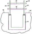
FIG. 6 is an elevational view of the armrest assembly of FIG. 3 installed in a side or pit of a roadway;
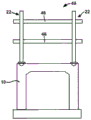
FIG. 7 is an elevation view of an installation culvert for the armrest assembly of FIG. 3; and
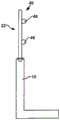
figure 8 is an end view of the installation of the handrail assembly of figure 3 on a concrete deck.
Detailed Description
The present invention relates to the attachment of a handrail support to a concrete slab, for example of the type used in road construction. However, it is not limited to such use only on concrete slabs.
According to a preferred embodiment, the invention contemplates use with precast concrete panels, such as the deck 10 shown in fig. 1. This is a concrete slab. One of the faces 10 is typically provided with a recess 12, such as an upper edge surface 10.1. The groove 12 is generally arcuate. In addition, such a board normally has a connecting element 14, the connecting element 14 having an upper part 14.1 in the form of a lug projecting from the lowermost end 18 of the recess, and the connecting element 14 having a lower part 14.2 embedded in the board 10 for securing the connecting element to the board (see fig. 3).
The ears 14.1 in the recesses 14 generally do not exceed the plane 10.1 of the deck.
In addition, the ears 14.1 are within the lateral extent of the panel 10, and they do not extend beyond the two opposite side walls 10.2 of the panel 10 in the panel 10.
Each connecting element 14, and therefore each lug 14.1, includes a narrow stem 14.3 and an upper shoulder 14.4, the upper shoulder being wider than the stem.
The lifting lugs 14.1 are used on a trolley (not shown) to lift the panels 10 and, according to a preferred embodiment, they may also be used in the present invention as described in more detail below.
Referring to fig. 3, an armrest support assembly 20 is shown. The kit 20 includes a bracket member 22, the bracket member 22 being mounted to a connector assembly 24.
The bracket assembly 22 includes a rod 26 having an internal bore 28, an internally threaded nut 30 secured to a lower end of the rod, and a plate 32 secured to an opposite side of the lower end of the nut.
The plate 32 extends far beyond the lateral outer ends of the stem 26 and nut 30.
The connector assembly 24 includes a locking portion 34 and a rod-like anchoring portion 36 integrally connected together. Accordingly, the anchor portion 36 is hereinafter referred to as a bolt.
The locking portion 34 comprises a first wall 34.1 in the shape of a circular arc. Accordingly, the first wall is hereinafter referred to as a curved wall. The curved wall 34.1 defines a slot 38. Since the groove 38 is in the curved wall 34.1, it follows a curved path which is also a circular arc.
As shown in fig. 4, one end 38.1 of the slot 38 is closed and the other end 38.2 opens into a wide aperture 40.
The curved wall 34.1 is connected to a second flat upper wall 34.2, such that the curved upper wall defines the inner space 42 of the locking portion 34. Such that the locking portion 34 is substantially hollow.
The anchor bar 36 is connected to the upper wall 34.2 and has an external thread 36.1. The external thread 36.1 is complementary to the thread of the nut 30.
When the bracket assembly 22 is in the use position as shown in fig. 3, the anchor rod 36 extends through the plate 32 and the nut 30 and into the internal bore 28.
As shown in fig. 3, the manner of mounting the holder kit 20 to the position is as follows.
To install the bracket assembly 20, the bracket member 22 is placed over the connector member 24 such that the anchor bar 36 can only be partially threaded into the internal bore 28, as shown in FIG. 5. In this configuration, the locking portion 34 is seen spaced from the plate 32.
In order to connect the locking portion 34 and the lifting lug 14.1, the bracket set 20 forms an acute angle with the vertical, as shown in fig. 5. Due to the distance between the plate 32 and the locking portion 34, there is sufficient space for the bracket assembly 20 to be positioned in this way without the plate being obstructed by the upper surface 10.1 of the plate surface 10.
The holder assembly 20 is partially disposed in the recess 12 and moved relative to the shackle 14.1, such that the shoulder 14.4 of the shackle is received through the aperture 40,
when the shoulder portion 14.4 passes through the aperture 40, the stem portion 14.3 may slide along the groove 38. This can be accomplished by rotating the holder assembly 20 from an acute angle in the direction of arrow 43, as shown in fig. 5, to position it substantially in the vertical direction as shown in fig. 3. In particular, the locking portion 34 forms a hook which in effect hooks over the shackle 14.1.
When the stent kit 20 is in the vertical position, the stent element 22 may be rotated relative to the connector element 24 about the longitudinal axis 44 of the stent such that the nut 30 is rotated relative to the anchor rod 36.
The external thread 36.1 of the anchor rod 36 and the thread of the nut 30 are then rotated relative to one another, so that the carrier element 22 is fixed tightly to the connector element 24.
After full securement, the bracket member 22 is moved downwardly relative to the connector member 24 until the surfaces 10.1 of the discs 32 and sla10 are fully secured and reinforced.
In this position, the connector element 24 pulls the lug 14.1 upwardly so that the lug is securely retained on the bracket assembly 20.
Although the connection of the shoulder 14.4 of the lug 14.1 to the curved wall 34.1 of the connector element 24 is not shown in figure 3, in use, in order for the connector element to pull the lug upwardly and secure the lug thereto, the curved wall needs to contact the shoulder in order for the lug to exert a securing force on the connector.
The plate 32 helps to prevent lateral rotational movement (i.e. movement away from the vertical) of the carrier element 22 as the plate is supported by the surface 10.1 of the deck 10.
The same procedure may be used to install similar bracket sets 20 in similar recesses 14 and lugs 14.1 in the deck 10.
As shown in fig. 6, 7 and 8, a horizontally extendable rail, such as rail 46, may be mounted to the frame member 22 to complete the mounting of the armrest 48. For this purpose, suitable connectors (not shown) may be used, such as clips, nuts and bolts, or even welding, to fixedly mount the armrest on the fixed base.
As shown in fig. 6, the plate 10 is different from that shown in fig. 1 in that it is shaped like a water tank or a concave and is installed on a horizontal surface of a road surface 50. The horizontal plane of the road surface 50 is visible relative to the board 10.
As shown in fig. 7, the shape of the plate 10 is a culvert type, and the shape of the plate is a concrete wall type in fig. 8.
While the above description relates to the installation of handrail assembly 20 on a concrete slab, such as precast slab 10, embodiments of the present invention also include installation on a precast slab or the like. For this reason, the following description will use like reference numerals in fig. 1 and 2.
In particular, according to such an embodiment, in the groove 12 the plate 10 is cast with the lower portion 14.2 of the connecting element 14, which is embedded in place.
In fig. 1, the lifting lugs 14.1 are mounted in the panel 10 to lift the panel in a uniform manner, and also to secure the handrails 48. The mounting position need not be very accurate for lifting purposes, but can be determined based on the position of the armrest.
When the board 10 is secured, a suitably shaped member (not shown) may be provided as the recess 12, which may have a rounded or similarly shaped surface.
It should be noted that the present invention, as described above, can be used to mount the armrest 48 on a fixed or temporary base. In particular, the mounting of the set of brackets 20 on the lifting lugs 14.1 and thus on the panel 1.0 during the fixing on the temporary base makes it easy to remove the handrail, and on the contrary, the above-mentioned mounting of the handrail.
In addition, the present invention may help to avoid drilling holes for bolts when fixing the handrail.
As described above, the lifting lug 14.1 is located in the side boundary of the deck 10, which means that the handrail 48 is also located in the side boundary. Thus, when filling with material, such as concrete, the concrete can be poured immediately into contact with the deck 10 without the handrail 48 being soiled.
While the invention has been described in connection with preferred embodiments, it will be understood by those skilled in the art that it is not limited to those embodiments, but is capable of many other forms.
For example, the attachment portion is in the form of an ear 14.1 as described above, and the locking portion 34 is described as being adapted to be attached to the ear, these elements being replaceable by other elements. For example, the connecting portion may be formed of other suitable components, in addition to those described above, as holes, recesses, openings or projections that connect with the locking portion 34.
In addition, these elements may be made as connecting portions to connect with the locking portions.
Claims (16)
1. A handrail support assembly adapted to be mounted to a concrete slab, the building element comprising a rectangular parallelepiped precast concrete slab having a front face and an opposite rear face and having a vertical operating direction, in which direction said front and said back face extend upwards, and in which direction the board further comprises an upper edge and an opposite lower edge, and two opposed side edges, each of the upper edge, the lower edge, and the side edges extending between the front surface and the rear surface, the concrete deck further comprising a securing element having a connecting portion exposed at the deck, and an anchor portion precast into and embedded in the deck and shaped to engage the deck, whereby the anchor member lifts the concrete deck by the lifting device when the lifting device is connected to the connecting portion, the bracket assembly comprising:
a handrail support having a first engagement element; and
a fastening element connector having a first portion adapted to be removably connected to the attachment portion and a second portion having a second engagement element and adapted to be connected to the armrest support,
wherein the handrail support and the second portion are adapted to be fastened to each other by mutual engagement of the first engagement element and the second engagement element, such that the handrail support is tightly fixed to the board,
wherein the armrest support kit has at least one outer surface adapted to conceal the first and second engagement elements when the armrest support and second portion are secured to one another.
2. A handrail support assembly according to claim 1, adapted for mounting to a concrete slab, wherein the front surface extends in a first plane and the rear surface extends in a second plane, the second plane being spaced from and parallel to the first plane, and wherein the fixing element is located between the first plane and the second plane.
3. A handrail support assembly according to claim 1 or claim 2, adapted to be mounted to a concrete slab, wherein the slab has a plurality of surfaces and defines a recess in one of the surfaces, the fixing element being located in the recess.
4. A handrail support assembly according to claim 1, adapted for mounting to a concrete slab, wherein the attachment portion of the fixing element and the first portion of the fixing element connector are adapted to hook onto each other.
5. An arm rest support assembly according to claim 1, adapted for mounting to a concrete slab, wherein said attachment portion of the fixing element is in the form of an eye-tab.
6. An arm rest support kit according to claim 5 adapted for mounting to a concrete slab, wherein the attachment portion comprises a stem portion and a shoulder portion wider than the stem portion, and the first portion of the fixing element connector comprises a recess for receiving the stem portion such that the first portion is adapted to be retained by the shoulder portion.
7. A handrail support assembly according to claim 6, adapted for mounting to a concrete slab, wherein the recess extends along a curved path such that the fixing element connector is pivotally connected to the fixing element relative to the slab by the fixing element connector.
8. A handrail support assembly according to claim 1, adapted for mounting to a concrete slab, wherein the second part of the fixing element connector comprises a threaded rod and the handrail support comprises a complementary threaded bore adapted for connection to the threaded rod, and wherein the fixing element connector and the handrail support are interconnected by the threaded portion.
9. A handrail support assembly according to claim 8, adapted for mounting to a concrete slab and adapted for connection to the fixing element connector and fixing element by rotation of the threaded rod and threaded bore.
10. A handrail support assembly according to claim 1, adapted for mounting to a concrete slab, wherein the handrail support comprises at least one laterally extending support for securing the upper surface of the slab when the handrail support is secured tightly to the slab.
11. A handrail support assembly according to claim 10, wherein the support is in the form of a plate.
12. An armrest system comprising:
a concrete panel comprising a rectangular parallelepiped precast panel having a front face and an opposite rear face and having a vertical operating direction in which said front and rear faces extend upwardly, the panel further comprising, in the operating direction, an upper edge and an opposite lower edge, and two opposite side edges, each of the upper edge, lower edge, and side edges extending between a front face and a rear face, the concrete panel further comprising a securing element having a connecting portion exposed at the panel face, and an anchor portion precast into and embedded in the panel face and shaped to engage the panel face, whereby the securing element lifts the concrete panel face by lifting means,
a handrail support having a first engagement element; and
a fastening element connector having a first portion adapted to be removably connected to the attachment portion and a second portion having a second engagement element and adapted to be connected to the armrest support,
wherein the handrail support and the second portion are adapted to be fastened to each other by mutual engagement of the first engagement element and the second engagement element, such that the handrail support is tightly fixed to the board,
wherein the arm support has at least one outer surface adapted to conceal the first and second engagement elements when the arm support and the second portion are secured to one another.
13. A handrail system according to claim 12, wherein the front surface extends in a first plane and the rear surface extends in a second plane, the second plane being spaced from and parallel to the first plane, and wherein the fixing element is located between the first plane and the second plane.
14. A method of installing a handrail assembly on a rectangular parallelepiped precast concrete deck having a front face and an opposite rear face and having a vertical operating direction in which said front and rear faces extend upwardly, the deck further including an upper edge and an opposite lower edge and two opposite side edges, each of the upper edge, lower edge and side edges extending between a front face and a rear face, the concrete deck further including a securing element having an attachment portion exposed at the deck and an anchor portion precast into and embedded in the deck and shaped to engage the deck whereby the securing element lifts the concrete deck by lifting means, the method comprising:
there is provided an armrest support kit comprising an armrest support having a first engagement element, and a fixing element connector having a first portion adapted to be removably connected to a connection portion, and a second portion having a second engagement element and adapted to be connected to the armrest support;
an armrest support removably connected to the second portion; and
the handrail support and the second portion are fastened to each other by the mutual engagement of the first engaging element and the second engaging element, so that the handrail support is tightly fixed to the board surface,
wherein the armrest support kit has at least one outer surface adapted to conceal the first and second engagement elements when the armrest support and second portion are secured to one another.
15. The method of claim 14, comprising attaching the handrail to a handrail support.
16. A method according to claim 14 or 15, wherein the slab is a concrete slab.
Applications Claiming Priority (3)
| Application Number | Priority Date | Filing Date | Title |
|---|---|---|---|
| AU2013904713A AU2013904713A0 (en) | 2013-12-04 | Handrail installation | |
| AU2013904713 | 2013-12-04 | ||
| PCT/AU2014/050396 WO2015081387A1 (en) | 2013-12-04 | 2014-12-03 | Handrail assembly, system and method of installation |
Publications (2)
| Publication Number | Publication Date |
|---|---|
| CN106460403A CN106460403A (en) | 2017-02-22 |
| CN106460403B true CN106460403B (en) | 2020-02-18 |
Family
ID=53272650
Family Applications (1)
| Application Number | Title | Priority Date | Filing Date |
|---|---|---|---|
| CN201480074849.1A Active CN106460403B (en) | 2013-12-04 | 2014-12-03 | Armrest kit, armrest system and installation method |
Country Status (8)
| Country | Link |
|---|---|
| US (1) | US10480211B2 (en) |
| EP (1) | EP3077607B8 (en) |
| CN (1) | CN106460403B (en) |
| AU (1) | AU2014360676B2 (en) |
| DK (1) | DK3077607T3 (en) |
| ES (1) | ES2954833T3 (en) |
| FI (1) | FI3077607T3 (en) |
| WO (1) | WO2015081387A1 (en) |
Families Citing this family (6)
| Publication number | Priority date | Publication date | Assignee | Title |
|---|---|---|---|---|
| CN106368490B (en) * | 2016-08-31 | 2019-02-26 | 国网山东省电力公司莒南县供电公司 | A kind of transmission tower under corrosive environment |
| US10689857B2 (en) * | 2017-03-16 | 2020-06-23 | Hector Van Lennep | Railing system with concealed anchor system |
| GB2595356A (en) * | 2020-05-22 | 2021-11-24 | Delta Uk Holdings Ltd | Baluster arrangement |
| DK180953B1 (en) * | 2020-12-30 | 2022-08-10 | Crh Concrete As | A safety device |
| GB2619274A (en) * | 2022-05-24 | 2023-12-06 | Westgate Global Ltd | Hitch assembly |
| WO2023239673A1 (en) * | 2022-06-06 | 2023-12-14 | Fortress Iron, Lp | Concrete embedded post anchor |
Citations (3)
| Publication number | Priority date | Publication date | Assignee | Title |
|---|---|---|---|---|
| GB1138339A (en) * | 1965-12-28 | 1969-01-01 | Geoffrey William Thomas | Support apparatus, particularly but not exclusively for games posts |
| EP1686223A3 (en) * | 2004-11-24 | 2012-05-09 | Stephan Kalina | Ground anchor |
| CN202882454U (en) * | 2012-10-18 | 2013-04-17 | 中国建筑第八工程局有限公司 | Temporary safe protective barrier |
Family Cites Families (16)
| Publication number | Priority date | Publication date | Assignee | Title |
|---|---|---|---|---|
| US3225501A (en) * | 1962-10-23 | 1965-12-28 | Mccaron Joseph | Fence post |
| DE1801457C3 (en) | 1968-10-05 | 1974-06-27 | Juergen 7800 Freiburg Goldberg | Device for lifting and transporting precast concrete parts or the like |
| JPS5651567Y2 (en) | 1977-05-09 | 1981-12-02 | ||
| DE8114740U1 (en) * | 1981-05-19 | 1982-01-21 | Robusta-Gaukel Gmbh, 7252 Weil Der Stadt | MONEY HOLDER |
| DE19653985A1 (en) * | 1996-12-21 | 1998-06-25 | Daniel Maechtle | Device for attaching bolt anchors to concrete structures |
| US6547223B1 (en) | 1997-09-18 | 2003-04-15 | John Letourneau | Rail stanchion for concrete slab walls |
| FR2871827B1 (en) | 2004-06-18 | 2008-11-07 | Ingenierie Et Commercialisatio | MOUNTING PLOT IN A SLAB AND ARRANGEMENT USING THE SAME |
| US7055807B2 (en) * | 2004-06-25 | 2006-06-06 | Pool Cover Corporation | Expandable pole socket with twist and lock insert |
| US7513083B2 (en) * | 2004-08-17 | 2009-04-07 | Simpson Strong-Tie Company, Inc. | Rotating concentric holdown |
| EP1686233A1 (en) | 2005-02-01 | 2006-08-02 | Telesteps AB | Collapsible combination ladder |
| US20080179477A1 (en) * | 2007-01-31 | 2008-07-31 | Regency Innovations, Llc | Scaffolding securement system |
| FR2914672B1 (en) | 2007-04-03 | 2010-03-19 | Kp1 | DEVICE FOR FIXING A POTELET ON THE SURFACE OF A CONCRETE FLOOR |
| US8365485B2 (en) * | 2008-01-16 | 2013-02-05 | Willy Reyneveld | Method and apparatus for setting support columns within a foundation |
| JP5366478B2 (en) * | 2008-08-25 | 2013-12-11 | 株式会社サンレール | Handrail support structure |
| US8827037B2 (en) * | 2011-01-25 | 2014-09-09 | National Trench Safety, Llc | Safety rail system and method for using same |
| JP6764667B2 (en) * | 2016-03-24 | 2020-10-07 | ジャパンライフ株式会社 | Safety fence base |
-
2014
- 2014-12-03 AU AU2014360676A patent/AU2014360676B2/en active Active
- 2014-12-03 FI FIEP14868430.1T patent/FI3077607T3/en active
- 2014-12-03 US US15/102,163 patent/US10480211B2/en active Active
- 2014-12-03 WO PCT/AU2014/050396 patent/WO2015081387A1/en active Application Filing
- 2014-12-03 DK DK14868430.1T patent/DK3077607T3/en active
- 2014-12-03 ES ES14868430T patent/ES2954833T3/en active Active
- 2014-12-03 EP EP14868430.1A patent/EP3077607B8/en active Active
- 2014-12-03 CN CN201480074849.1A patent/CN106460403B/en active Active
Patent Citations (3)
| Publication number | Priority date | Publication date | Assignee | Title |
|---|---|---|---|---|
| GB1138339A (en) * | 1965-12-28 | 1969-01-01 | Geoffrey William Thomas | Support apparatus, particularly but not exclusively for games posts |
| EP1686223A3 (en) * | 2004-11-24 | 2012-05-09 | Stephan Kalina | Ground anchor |
| CN202882454U (en) * | 2012-10-18 | 2013-04-17 | 中国建筑第八工程局有限公司 | Temporary safe protective barrier |
Also Published As
| Publication number | Publication date |
|---|---|
| EP3077607B1 (en) | 2023-06-07 |
| EP3077607B8 (en) | 2023-09-13 |
| AU2014360676A1 (en) | 2016-07-21 |
| FI3077607T3 (en) | 2023-09-11 |
| AU2014360676B2 (en) | 2019-01-03 |
| WO2015081387A1 (en) | 2015-06-11 |
| EP3077607A4 (en) | 2017-07-26 |
| CN106460403A (en) | 2017-02-22 |
| US20160312491A1 (en) | 2016-10-27 |
| NZ721839A (en) | 2021-04-30 |
| EP3077607A1 (en) | 2016-10-12 |
| ES2954833T3 (en) | 2023-11-27 |
| DK3077607T3 (en) | 2023-09-18 |
| US10480211B2 (en) | 2019-11-19 |
Similar Documents
| Publication | Publication Date | Title |
|---|---|---|
| CN106460403B (en) | Armrest kit, armrest system and installation method | |
| KR101023660B1 (en) | Retaining Wall using Anchor and Concrete Panel and its Construction Method | |
| RU2553813C2 (en) | Method and device to strengthen and lighten bearing structures of floor and roof | |
| KR101765762B1 (en) | Cantilever part for bridge and constructing method thereof | |
| JP6393350B2 (en) | Repair method for existing waterways | |
| KR100817901B1 (en) | Reinforced Earth Retaining Wall Structure of Perforated Slope | |
| EP3420138B1 (en) | Anchoring device for a fence | |
| KR101066837B1 (en) | Lifting and bearing apparatus preventing fracture on the pier or abutment of bridge | |
| JP2017082404A (en) | Superstructure of t-girder bridge | |
| JP5041481B2 (en) | Updating method and structure of existing bearing device | |
| KR102127192B1 (en) | Retaining wall reinforced load resistance, and manufacturing method thereof | |
| JP3893551B2 (en) | Rock bolt bearing plate device | |
| KR101534058B1 (en) | Soil retaining wall for load support and constructing method thereof | |
| AU2012101074A4 (en) | A component tunnel ceiling structure and method of installing the same | |
| JP2004169375A (en) | Drain gutter structure | |
| KR200298097Y1 (en) | Mold supporting structure | |
| KR200382207Y1 (en) | Bridge inspection passage | |
| JP3597824B2 (en) | Construction method of overhang road | |
| KR101436563B1 (en) | Water storage tank and method for constructing thereof | |
| JP2515227B2 (en) | Installation method of cast-in-place concrete foundation and precast concrete wall slab | |
| KR101059539B1 (en) | Block for road extension | |
| JP2003321913A (en) | Method for repairing handrail and attachment device for new handrail | |
| KR200351432Y1 (en) | Wing type of footpath block | |
| JPH06264416A (en) | Method of installing snowslide prevention fence | |
| KR100569723B1 (en) | Structure for Installing Shear Connector in Concrete Girder |
Legal Events
| Date | Code | Title | Description |
|---|---|---|---|
| C06 | Publication | ||
| PB01 | Publication | ||
| C10 | Entry into substantive examination | ||
| SE01 | Entry into force of request for substantive examination | ||
| GR01 | Patent grant | ||
| GR01 | Patent grant |