CN1062663C - Optical fiber cable - Google Patents
Optical fiber cable Download PDFInfo
- Publication number
- CN1062663C CN1062663C CN95109455A CN95109455A CN1062663C CN 1062663 C CN1062663 C CN 1062663C CN 95109455 A CN95109455 A CN 95109455A CN 95109455 A CN95109455 A CN 95109455A CN 1062663 C CN1062663 C CN 1062663C
- Authority
- CN
- China
- Prior art keywords
- groove
- ribbon
- fiber
- spiral slot
- optical cable
- Prior art date
- Legal status (The legal status is an assumption and is not a legal conclusion. Google has not performed a legal analysis and makes no representation as to the accuracy of the status listed.)
- Expired - Lifetime
Links
Images


Classifications
-
- G—PHYSICS
- G02—OPTICS
- G02B—OPTICAL ELEMENTS, SYSTEMS OR APPARATUS
- G02B6/00—Light guides; Structural details of arrangements comprising light guides and other optical elements, e.g. couplings
- G02B6/44—Mechanical structures for providing tensile strength and external protection for fibres, e.g. optical transmission cables
- G02B6/4401—Optical cables
- G02B6/4407—Optical cables with internal fluted support member
- G02B6/4408—Groove structures in support members to decrease or harmonise transmission losses in ribbon cables
-
- G—PHYSICS
- G02—OPTICS
- G02B—OPTICAL ELEMENTS, SYSTEMS OR APPARATUS
- G02B6/00—Light guides; Structural details of arrangements comprising light guides and other optical elements, e.g. couplings
- G02B6/44—Mechanical structures for providing tensile strength and external protection for fibres, e.g. optical transmission cables
- G02B6/4401—Optical cables
- G02B6/4415—Cables for special applications
- G02B6/4416—Heterogeneous cables
- G02B6/4422—Heterogeneous cables of the overhead type
Abstract
An optical fiber cable provided with a grooved spacer having on its outer circumference at least one SZ-spiral groove formed continuously along its longitudinal direction and at least one optical fiber tape accommodated in the groove of the grooved spacer, wherein the inverting angle, showing the rotational angle in the circumferential direction of the grooved spacer from one inverting portion of the SZ-spiral groove of the grooved spacer to the next inverting portion, is at least 180 DEG and wherein the optical fiber tape is accommodated in the groove in a state where the tape surface faces the bottom of the SZ-spiral groove at the center portions between inverting portions of the SZ-spiral groove and in a state where the tape side edges, which would be positioned at the inside of the bends of the groove of the inverting portions when assuming that the optical fiber tape were accommodated in the groove in a state where the tape surface faced the groove bottom at the inverting portions of the groove, face the groove bottom.
Description
The present invention relates to a kind of optical cable, particularly a kind of optical cable that uses the trough of belt lining that forms the SZ spiral slot; Lining periphery constituting optical cable is formed with the SZ spiral slot along the liner sleeve length direction, and ribbon fiber (fibre ribbon) is placed groove.
Optical fiber is located at coverings described fibre core periphery, diameter 125 μ m by fibre core, and peripheral resin coating cap rock constitutes.
Such light is capable, in most cases uses many to be banded fibre bundle.
Use places the advantage of the optical cable in the groove to be optical fiber at its peripheral trough of belt lining that forms the SZ spiral slot, when connecting or when doing terminal the processing, takes out optical fiber easily in groove.This class optical cable, known use ribbon fiber is its optical fiber, have and multi-ribbon shape optical fiber is placed person in the groove along the depth direction of groove stackedly (spy opens flat 2-83507 communique, Te Kaiping 5-203849 communique), and along the Width of groove place person in the groove (spy opens flat 4-55803 communique) stackedly.
The SZ spiral slot is in the lining periphery that constitutes optical cable, forms the wavy groove of punctuated turning over continuously along the liner sleeve length direction.That is to say that the SZ spiral slot is not the groove that forms one-way spiral (is S direction screw type, or Z direction screw type), but along the wave mode of the peripheral formation cycle upset of optical cable.Also promptly, the SZ spiral slot, the sense of rotation of its groove becomes punctuated turning over.
So form the lining of SZ spiral slot, when ribbon fiber connects, also or during terminal the processing, have the advantage that is easy to taking-up optical fiber in groove in the periphery.
Te Kaiping 2-83507 communique and special open to have disclosed in the flat 5-203849 communique multi-ribbon shape optical fiber is placed optical cable in the groove along the depth direction of groove stackedly.
Disclosed ribbon fiber stackedly in the flat 4-55803 communique and open, ribbon fiber has been placed optical cable in the groove along the Width (laterally) of SZ spiral slot the spy.
Ribbon fiber is with multifiber abreast and come in the same plane, adds common obducent ribbon.Therefore, for the bending that makes banded plain bending direction, every optical fiber has identical bending, the increase of loss can take place hardly, if but add the bending (bending of the rib width of cloth) of lateral margin direction in the banded plane towards band, then produce compression to distortion, and the optical fiber in the bending direction outside produces and upholds to distortion at the inboard optical fiber on one side of bending direction, since this distortion, the increase that can produce big loss.
Below be described in detail the generation of loss.If place the groove of ribbon fiber is at the peripheral unidirectional swivelling chute that forms of lining, and ribbon fiber is placed unidirectional swivelling chute, is wound into optical cable, and good owing to putting, ribbon fiber does not have too big distortion.But, at the peripheral formation of lining wave mode SZ rotation shape groove, because multi-ribbon shape optical fiber for each ribbon optical fiber, will inevitably produce the extention to the lateral margin direction bending of band with respect to the direction of SZ rotation shape groove, along certain direction layered laminate ground placement.For example, just as the spy opens flat 2-83507 communique and special opening disclosed in the flat 5-203849 communique, along in the optical cable of the stacked placement of groove depth direction, each ribbon fiber mainly is subjected to making it bending towards the lateral margin bending direction of band in the flip portion of SZ spiral slot at multi-ribbon shape optical fiber.And open flat 4-55803 those disclosed herein as the spy, along in the optical fiber of the stacked placement of groove width direction, then main middle body in (flip portion is between the next flip portion) between the flip portion of SZ spiral slot is subjected to towards the bending of the lateral margin bending direction of band at multi-ribbon shape optical fiber.For this reason, loss all can take place in which kind of situation.
Therefore, use the trough of belt lining that the SZ spiral slot is arranged, ribbon fiber is placed the optical cable of type in this groove, owing to must add the stress of undue bending in the ribbon fiber, not only can increase the loss of optical fiber, the long term reliability aspect also has problem, is difficult to practicability.But, the optical cable of the lining of SZ spiral slot is arranged, said just as the front, when the connection of ribbon fiber or terminal the processing, it has the advantage that is easy to take out optical fiber in groove.
In view of above problem, the object of the present invention is to provide the optical cable of type in a kind of SZ spiral slot that ribbon fiber is placed the trough of belt lining, have the optical fiber of preventing and bend or be out of shape the structure that can have minimum loss to increase.
The present invention also aims to provide a kind of and can keep long-term reliability, have the optical cable of band SZ spiral slot lining.
According to the present invention, a kind of optical cable is provided, be formed up to the trough of belt lining of a rare continuous SZ spiral slot in its periphery along its length, and in the groove of this trough of belt lining, hold a ribbon optical fiber at least.In this optical cable
(a) expression from a flip portion of the SZ of described trough of belt lining spiral slot flip angle to next flip portion along this trough of belt lining circumferencial direction angle of revolution greater than 180 °;
(b) described ribbon fiber is sentenced the state of its zone face at the bottom of the SZ spiral slot in the middle body between the aforementioned SZ spiral slot flip portion, and at the flip portion place of described groove, if supposition was placed towards the bottom land state with zone face originally,, so described ribbon fiber is placed in the described groove then to be positioned at the state of " curved interior of the groove of flip portion " fibre ribbon lateral margin on one side at this towards bottom land.
Usually, the groove of trough of belt lining changes along trough of belt liner sleeve length direction towards (opening towards).In the optical cable of the present invention, in the groove ribbon fiber towards about groove towards variation.Just ribbon fiber change its in groove towards, so that its centre between the groove flip portion is that zone face is towards bottom land, and be zone face crooked situation in groove originally at groove flip portion place, the fibre ribbon lateral margin that now forms curved interior one side is towards bottom land (being that fibre ribbon stands in the groove).If like this in the geosyncline towards variation, will make the no matter centre between the flip portion of groove of ribbon fiber, also or upset place of groove, mainly all be along the direction bending that makes the zone face bending, but almost not additional bending towards the lateral margin direction.In addition, ribbon fiber seldom adds twisting.Thus, make the fiber transmission attenuation in the ribbon fiber add minimum.
Have again, the flip angle that makes groove is greater than 180 °, this is because will make state from the ribbon fiber zone face of the middle body between the flip portion of groove towards bottom land to the lateral margin of the flip portion band of the groove state towards bottom land, it is undue in variation not have in the middle of this, and that just will have 90 ° angle of revolution at least.So that the flip angle of groove is necessary greater than 180 °.
The flip angle of aforementioned SZ spiral slot is preferably in 180 ° to the 360 ° scopes.If the flip angle of groove surpasses 360 °, sensitive for damages when then in groove, taking out ribbon fiber.If consider to be easy to take out ribbon fiber in groove, the flip angle of groove is less than 360 °.Thereby the flip angle of selected groove is in 180 ° of-360 ° of scopes usually.The preferred range of the flip angle of groove is 210 °-330 °; Be preferably 270 ° of-300 ° of scopes.
When multi-ribbon shape optical fiber is placed the situation of a SZ spiral slot, preferably make aforementioned more than ribbon optical fiber settle by stacked state.Middle body between described SZ spiral slot flip portion stacks along the groove depth direction, then stacks along the well width direction in the flip portion of groove.
In addition, preferably the cross dimensions of SZ spiral slot is set at the section circumscribed circle that makes multi-ribbon shape optical fiber duplexer and is contained in size in the groove.
Under specific circumstances, if ribbon fiber is wide to be W, thick is T, and when the lamination number was N, the cross dimensions of the SZ spiral slot of then described trough of belt lining, the inscribed circle of groove (with groove bottom and two these three circles that face joins of medial surface) diameter E and groove depth D satisfied relational expression down:
D≥E≥[W
2+(NT)
2]
1/2 (mm)
If press the inscribed circle diameter E and the groove depth D of following formula setting slot, then the size of groove is bigger than the catercorner length of ribbon fiber laminated body (containing one situation); It is no undue in change to be laminated in the groove for ribbon fiber.Therefore, when ribbon fiber is subjected to flexion or twisting, disperse internal stress easily.So the size of setting slot as above is effective to the increase that suppresses fiber transmission attenuation.
The SZ spiral slot of aforementioned trough of belt lining be shaped as rectangle the time, because of the inscribed circle diameter E of groove equals well width B, so groove width B and groove depth D satisfy following relational expression:
D≥B≥{W
2+(NT)
2}
1/2 (mm)
If set groove width B and groove depth D as following formula, can suppress fiber transmission attenuation effectively increases.
Ribbon fiber preferably has the optical fiber of 4 above fibre cores.Fibre core number in the ribbon fiber is many more, and then its width is big more, will make fibre ribbon become big towards the harmful effect of lateral margin direction bending, and the present invention then has special-effect for the situation of using the bigger ribbon fiber of the above width of 4 cores.
Once more, the ribbon fiber in the described SZ spiral slot is preferably there to be unnecessary length along its length.
Under specific circumstances, ribbon fiber is wide to be W, and thick is T, when the lamination number is N, and the size of the SZ spiral slot section of then described trough of belt lining, groove inscribed circle (with groove bottom and two these three circles that face joins of side) diameter E, and groove depth D satisfies the following formula relation:
D≥E≥[W
2+(NT)
2]
1/2 (mm)
And, when with the surplus long rate β of following formula regulation ribbon fiber, promptly
β={ (L-L
o)/L
o} * 100 (%) are wherein: L
oBe the flute length of trough of belt lining,
L is the length that is installed in the ribbon fiber in groove, and the depth D of then aforementioned inscribed circle diameter E and groove satisfies following relational expression:
D≥E≥[(β+0.1)
2/0.08}+NT (mm)
In the SZ of aforementioned trough of belt lining spiral slot situation in a rectangular shape, groove inscribed circle diameter E equates that with well width B then well width B and groove depth D will satisfy following relational expression:
D≥B≥{W
2+(NT)
2}
1/2 (mm)
And, when after stipulating ribbon fiber, growing rate β, promptly by following formula
β={ (L-L
o)/L
o} * 100 (%) are wherein: L
oBe the flute length of trough of belt lining,
L is the ribbon fiber length that is housed in the groove, and then aforementioned grooves width B and groove depth D will satisfy following formula:
D≥B≥{(β+0.1)
2/0.08}+NT (mm)
In optical cable, ideal situation is that optical fiber is not with respect to the elongation deformation of lining and deformation.So-called desirable, all the tensile deformation than optical cable is little promptly to wish the deformation of optical fiber in any case.It is exactly effective making the ribbon fiber that is installed in groove that unnecessary length is arranged for this reason.But, if ribbon fiber has unnecessary length, will in groove, form the fluctuating of ribbon fiber, produce macroscopical warpage problem.If press above-mentioned relation formula setting slot width B and groove depth D, consider that by the crooked deformation that macroscopical warpage caused of optical fiber and long-term reliability reply is installed in the necessary surplus long rate that ribbon fiber had in groove and is limited in less than 0.1%.
The section that preferably makes described SZ spiral slot is that 3 bottom land broadens towards opening from described width.
In aforesaid trough of belt lining, described SZ spiral slot is formed directly on the lining along the length direction of optical cable.Perhaps in aforementioned trough of belt lining, being a plurality of deep-slotted chip breaker parts that will each have groove constitutes to twisting joint mutually around tension part along SZ.
Be installed in the SZ spiral slot of described ribbon fiber or the SZ spiral slot that other is installed in single-core fiber preferably filling jelly.And preferably described ribbon fiber is supported on the buffer unit and is installed in described SZ spiral slot, and in being installed in the aforementioned SZ spiral slot of described ribbon fiber the filling jelly.
Preferably described trough of belt lining is supported along on its set Support Level.
With reference to accompanying drawing, by following description, will make above-mentioned purpose of the present invention and feature, and other purpose and further feature are clear and definite further, wherein:
Figure 1A and Figure 1B are sectional drawing and the side view of explanation as first kind of embodiment optical cable on optical cable of the present invention basis;
Fig. 2 is the trough of belt bush side view of optical cable of the present invention shown in Figure 1;
Fig. 3 A to Fig. 3 K be the explanation Figure 1B in the a-a line to k-k line place groove towards with ribbon fiber towards the sectional drawing that concerns an example;
Fig. 4 A to Fig. 4 K be the explanation Figure 1B in the a-a line to k-k line place groove towards with ribbon fiber towards the sectional drawing that concerns another example;
Fig. 5 A and Fig. 5 B illustrate that schematically ribbon fiber is installed in the sectional drawing of state in the SZ spiral slot;
Fig. 6 A and Fig. 6 B schematically illustrate ribbon fiber another kind of sectional drawing that is installed in state in the SZ spiral slot;
Fig. 7 is the ribbon fiber size of explanation optical cable of the present invention and the sectional drawing of trough of belt lining groove depth and inscribed circle size relationship;
Fig. 8 is the sectional drawing of size relationship of the groove of explanation ribbon fiber size of optical cable of the present invention and trough of belt lining;
Fig. 9 A and Fig. 9 B are as the sectional drawing of middle body and the flip portion sectional drawing of groove between the flip portion of the groove of the first embodiment optical cable of first kind of embodiment of optical cable of the present invention;
Figure 10 A to Figure 10 D is respectively the lamination situation sectional drawing of ribbon fiber;
Figure 11 A and Figure 11 B are as the sectional drawing of middle body and the flip portion sectional drawing of groove between the flip portion of the groove of the second embodiment optical cable of first kind of embodiment of optical cable of the present invention;
Figure 12 A to Figure 12 C is as the sectional drawing of middle body and the flip portion sectional drawing of groove between the flip portion of the groove of the 3rd embodiment optical cable of first kind of embodiment of optical cable of the present invention;
Figure 13 A to Figure 13 C is as the sectional drawing of middle body and the flip portion sectional drawing of groove between the flip portion of the groove of the 4th embodiment optical cable of first kind of embodiment of optical cable of the present invention;
What Figure 14 A and Figure 14 B schematically illustrated second kind of embodiment of optical cable of the present invention is installed in ribbon fiber the state that is installed in sectional drawing in the SZ spiral slot;
Figure 15 is the sectional drawing of the cable duct of the third embodiment of optical cable of the present invention;
Figure 16 A to Figure 16 C is the sectional drawing of middle body between the flip portion of the 4th kind of embodiment cable duct of optical cable of the present invention and the flip portion sectional drawing of groove;
Figure 17 A to Figure 17 C is the sectional drawing of middle body between the flip portion of the 5th kind of embodiment cable duct of optical cable of the present invention and the flip portion sectional drawing of groove;
Figure 18 is the key diagram of ribbon fiber fluctuating situation in the groove of the 6th kind of embodiment trough of belt lining of optical cable of the present invention;
Figure 19 A and Figure 19 B are the sectional drawings of the 6th kind of embodiment optical cable of the present invention;
Figure 20 A to Figure 20 C is the sectional drawing of middle body between the flip portion of the 5th kind of embodiment cable duct of optical cable of the present invention and the flip portion sectional drawing of groove;
Figure 21 is the sectional drawing of the self-cradling type optical cable of another embodiment of the present invention;
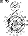
Figure 22 is the sectional drawing of the self-cradling type optical cable of the another embodiment of the present invention;
Figure 23 is the oblique view of the self-cradling type optical cable of the another embodiment of the present invention;
Figure 24 is the oblique view of the self-cradling type optical cable of the another embodiment of the present invention.
Below the embodiment of present invention will be described in detail with reference to the accompanying optical cable.
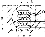
Figure 1A, Figure 1B, Fig. 2 and Fig. 3 A to Fig. 3 K are the optical cable basic block diagram of first kind of embodiment of expression optical cable of the present invention.
Figure 1A is provided in a side of the sectional drawing of the trough of belt lining 11 in the optical cable, and Figure 1B is that study plot is represented trough of belt lining 11 side view along its length.
Fig. 2 is the side view of a trough of belt lining 11, and it has a SZ spiral slot 13.This is to scheme more accurately than the diagram of Figure 1B.
The SZ spiral slot is the groove that S is formed to the groove combination of interactions of spiral (to left-handed) to the groove of spiral (to dextrorotation) and Z.In addition, notice that SZ spiral slot 13 forms groove direction punctuated turning over " wave mode " shape along the liner sleeve length direction; Not the groove that forms " one-way spiral type " around the lining.
Shown in Figure 1B, SZ spiral slot 13 with waveform towards punctuated turning over be formed on the circumference of trough of belt lining 11.The flip portion of coding 17 expression SZ spiral slots 13, middle body between the adjacent two upset portions 17 of coding 19 expression grooves (flip portion 17 of groove is to the middle body of 17 of next flip portion), symbol P are represented the upset pitch (the trough of belt lining central axis distance from a flip portion 17 to next flip portion 17) of groove.
In addition, so-called " curved interior of the groove of flip portion " is the 17a part of Fig. 2.That is to say that coding 17 is flip portion of groove 13, coding 17a is the curved interior of the groove of flip portion 17, and coding 17b is the curved outside of the groove of flip portion 17.
Symbol theta is the flip angle (from the angle of revolution of a flip portion 17 to next flip portion 17 along trough of belt lining circumferencial direction of groove) of groove among Figure 1A.In the present embodiment, θ=300 °.
Fig. 3 A to Fig. 3 K be respectively among Figure 1B the a-a line to the trough of belt lining 11 at k-k line place and the sectional drawing of ribbon fiber 15.Fig. 3 A is at the trough of belt lining 11 at flip portion 17 places and the sectional drawing of ribbon fiber 15, Fig. 3 F is the trough of belt lining 11 at middle body 19 places between the flip portion and the sectional drawing of ribbon fiber 15, and Fig. 3 K is the trough of belt lining 11 at adjacent (back side of optical cable) flip portion 17 places of flip portion 17 shown in Fig. 3 A and the sectional drawing of ribbon fiber 15.
In the present embodiment, in a SZ spiral slot 13, be installed in 3 bands dress optical fiber 15 with stacked state.SZ spiral slot 13 is not to form the one-way spiral shape along optical cable is peripheral, but is the wavy of punctuated turning over, and therefore, ribbon fiber 15 laminated body are reversed along SZ spiral slot 13 and imported in the SZ spiral slot 13.For this reason, for discern in the 3 ribbon optical fiber 15 each bar and towards, on the 2 ribbon optical fiber 15 of the outside, be printed on O and X mark respectively.
At Fig. 3 A to Fig. 3 K a upset pitch P only is shown, its next one that continues upset pitch can illustrate its situation by rightabout Fig. 3 K to Fig. 3 A, below other pitch then be concatenated to form alternately.
Be placed in the ribbon fiber in the SZ spiral slot 13, no matter in the flip portion 17 of SZ spiral slot 13, also or the middle body between flip portion 19, all should be crooked on the direction that the master tape face is bent.So this situation is that ribbon fiber 15 is towards the crooked minimum situation of the lateral margin direction of band.
And, so ribbon fiber 15 being housed in method in the SZ spiral slot, the twisting that produces on ribbon fiber 15 is minimum.Fig. 3 A to Fig. 3 K at first view, ribbon fiber 15 duplexers in the SZ spiral slot 13 seemingly are that the revolution twisting, in fact the a-a line in Figure 1B between the d-d line and the h-h line between the k-k line, just SZ spiral slot 13 towards changing, and the direction of ribbon fiber 15 does not almost change.This means that ribbon fiber 15 is not additional distortion in described interval; Only additional distortion is arranged on the interval ribbon fiber 15 to h-h at the d-d line.Also promptly, in whole flip angle θ=300 °, only in 90 °-210 °, distortion is arranged.
In the existing optical cable, twist to all adding everywhere the next flip portion at ribbon fiber from a flip portion.Compare with it, the optical cable of first kind of embodiment of the present invention has reduced the additional distortion of ribbon fiber significantly; Reduced the distortion of (θ=300 °)-120 °=180 ° on the pitch upset.Flip angle θ
The flip angle θ of the groove of trough of belt lining below is described.Ribbon fiber 15 becomes zone face towards Fig. 3 of bottom land D state from lateral margin towards Fig. 3 A condition of SZ spiral slot 13 bottom lands, SZ spiral slot 13 towards turning over 90 °.Equally, fade to Fig. 3 K state from Fig. 3 H state, SZ spiral slot 13 towards also turning over 90 °.In other words, for make ribbon fiber 15 at the lateral margin of the band at groove 13 flip portion 17 places towards bottom land, obtain the state of the zone face at middle body 19 places between flip portion towards bottom land, must make flip portion both sides groove separately towards turning over 90 ° along trough of belt lining circumferencial direction at least.
Therefore, the flip angle of the SZ spiral slot 13 of trough of belt lining 11 needs greater than 180 °.With regard to θ=180 °, ribbon fiber 15 is the situation completely without additional distortion.As previously mentioned, the upper limit of groove 13 flip angles is wished under 360 °.Therefore, usually flip angle is set in 180 ° of appropriate values to 360 ° of scopes.Flip angle is 210 °-300 ° preferably; Preferably 270 °-300 °.When so best flip angle θ, the distortion narrow range of ribbon fiber 15, its relevant stress is also very little, is difficult for taking place deformation.
Two spiral slots 13 shown in Fig. 3 A to Fig. 3 K towards with ribbon fiber 15 be ideal situation towards relation.In fact, because ribbon fiber 15 is freely in groove 13, can be because of the elasticity of ribbon fiber 15 self, rigidity or because of the bending force of upset portion etc., make its direction variation groove 13 in towards steady state (SS).Fig. 4 A to Fig. 4 K represents so concrete example.Fig. 4 A to Fig. 4 K be respectively among Figure 1B corresponding with Fig. 3 A to Fig. 3 K the a-a line to the sectional drawing of k-k line.
Shown in Fig. 4 F, middle body 19 places of ribbon fiber 15 between the flip portion of SZ spiral slot 13 are installed in groove 13 with the state of zone face towards bottom land.This point is identical with situation shown in Fig. 3 F.From state shown in Fig. 4 F, turning to of groove 13 turn over+90 °/-90 ° promptly shown in Fig. 4 C and Fig. 4 I, the ribbon fiber 15 in the SZ spiral slot 13 becomes be roughly erectility in groove.And shown in Fig. 4 A and Fig. 4 K, at flip portion 17 places of groove 13, ribbon fiber 15 is become the curved interior 17a state on one side of the groove of swinging to flip portion 17 by erectility with respect to SZ spiral slot 13 bottom surfaces.
What is called of the present invention " ribbon fiber 15 is sentenced the fibre ribbon lateral margin in groove 13 flip portion 17 and is housed in the groove 13 towards the state of bottom land " comprises Fig. 4 A, Fig. 4 K state.
Fig. 3 and Fig. 4 show SZ spiral slot 13 flip portion 17 places, all or part of contacts the side of ribbon fiber 15 duplexers with bottom land, but the situation of floating from bottom land because ribbon fiber 15 about the size of tension force or SZ spiral slot 13 flip angle θ, also has ribbon fiber 15 duplexers not contact bottom land.Fig. 5 A and Fig. 5 B are exactly the sectional drawing of this situation of expression.Wherein Fig. 5 A is that the sectional drawing of situation is floated from SZ spiral slot 13 bottom lands in presentation graphs 3A ribbon fiber duplexer side, and Fig. 5 B then is that the sectional drawing of situation is floated in presentation graphs 4B ribbon fiber 15 duplexer sides from bottom land.Coding 17a represents the inboard of flip portion 17 bendings, and coding 17b represents the outside of flip portion 17 bendings.The performance of relevant " ribbon fiber is housed in the groove with the state of fibre ribbon side towards bottom land in flip portion " also means the situation that ribbon fiber floats from SZ spiral slot 13 bottom lands shown in Fig. 5 A and Fig. 5 B among the present invention.
Be contained in ribbon fiber 15 duplexers in the SZ spiral slot 13, because of its multi-ribbon shape optical fiber 15 does not limit each other, so the complete stacked situation that just has each ribbon fiber 15 side never to stagger becomes side a little situation that how much staggers.Fig. 6 A and 6B illustrate the SZ spiral slot 13 of this situation and the sectional drawing of ribbon fiber 15.Wherein Fig. 6 A represents ribbon fiber 15 duplexers and the contiguous situation of SZ spiral slot 13 bottom lands, the layer-by-layer state of ribbon fiber 15 duplexers more or less staggers, and Fig. 6 B represents the situation that ribbon fiber 15 duplexers float from SZ spiral slot 13 bottom lands, and the layer-by-layer state of ribbon fiber 15 duplexers more or less staggers.The performance of relevant " ribbon fiber is housed in the groove with the state of fibre ribbon lateral margin towards bottom land in flip portion " among the present invention comprises also that the ribbon fiber duplexer has the situation that staggers shown in Fig. 6 A and Fig. 6 B.The trough of belt liner size
The size of the groove of trough of belt lining below is described.
For the zone face that in trough of belt lining 13, obtains ribbon fiber 15 towards the side of bottom land shape and band towards the bottom land shape, preferably make its lamination situation of duplexer of ribbon fiber 15 in the groove 13 be destroyed ground change relatively towards.On the one hand, the cross dimensions that make groove 13 changes along its length direction, is extremely difficult from the manufacturing of trough of belt lining.So, make the size of groove 13 all the same along whole length, can be by the size of following setting trough of belt lining groove 13.
Here it is is set at the size that is housed in ribbon fiber 15 duplexers (containing one deck situation) section circumscribed circle in the SZ spiral slot 13 with the cross dimensions of SZ spiral slot 13.The size of groove 13 that can following definite trough of belt lining 11.
As shown in Figure 7, be W, thick for T, when the lamination number is N (N=3 in Fig. 7 example) when ribbon fiber 15 is wide, inscribed circle (circle that joins with groove bottom and two side faces) the diameter E and the groove depth D that the cross dimensions of the groove 13 of described trough of belt lining 11 are set at its groove satisfy following formula:
D≥E≥[W
2+(NT)
2]
1/2 (mm)……(1)
Person as shown in Figure 8 particularly, at the SZ of described trough of belt lining spiral slot 13 is under the situation of rectangle, ribbon fiber is wide to be W, thick for T, when the lamination number is N (N=3 in Fig. 8 example), in order to obtain groove inscribed circle diameter E, groove width B etc., sets groove width B and groove depth D and satisfies following formula:
D≥B≥[W
2+(NT)
2]
1/2 (mm)……(2)
That is to say, make SZ spiral slot 13 width B and and depth D than the length [W of the diagonal L of N layer ribbon fiber 15
2+ (NT)
2]
1/2Greatly.So set the size of SZ spiral slot 13 because the width B of groove 13 and depth D all the catercorner length than ribbon fiber 15 duplexers is big, so the layer-by-layer state of ribbon fiber 15 duplexers in the groove 13 can be not destroyed, can not produce undue stress yet; Relative orientation may change, but does not make the stress of ribbon fiber 15 distortions, deformation can not take place.
In addition, if adopt extrusion modling manufactured trough of belt lining 11, then 13 two sidewalls of groove at groove 13 flip portion 17 places are oblique towards curved interior 17a one square neck of flip portion 17.Flip portion 17 places of groove 13 take place so to tilt, and can not hinder and hold ribbon fiber 15 duplexers.Under the situation that groove 13 flip portion 17 place's generation troughs 13 tilt, groove 13 width B and the depth D setting of other parts beyond groove 13 flip portion 17 can be satisfied relational expression (2).The embodiment 1 of first kind of embodiment
Following according to above-mentioned first kind of embodiment announcement specific embodiment.
Fig. 9 A and Fig. 9 B represent the more specifically section structure of first kind of embodiment of optical cable of the present invention.Fig. 9 A is sectional drawing middle body 19 theres between Figure 1B f-f line place groove 13 flip portion, and Fig. 9 B is sectional drawing Figure 1B a-a line or k-k line place groove 13 flip portion 17 theres.
Trough of belt lining 11A is a tygon extrusion modling body, and there is the tension element 21 of steel strand wires the center.Trough of belt lining 11A external diameter is 15.8mm, groover rot diameter 10mm.SZ spiral slot 13A does not have the rectangular cross section shown in Fig. 3 to Fig. 5 diagram, but opening is wide, the groove of narrow base.The cross dimensions of this groove 13A is the wide 1.3mm of bottom land, the wide 1.5mm in groove upper end, groove depth 2.3mm.The flip angle θ of groove 13A is about 300 °, and upset pitch P is about 240mm.
Be formed 8 groove 13A among the trough of belt lining 11A, wherein groove 13A is installed in the duplexer of 4 ribbon optical fiber 15, and groove 13A is installed in the duplexer of 2 ribbon optical fiber 15 every two groove 13A therewith.Shown in Fig. 9 A like that, middle body 19 places between groove 13A flip portion, the zone face of ribbon fiber 15 duplexers is towards bottom land, and shown in Fig. 9 B like that, at flip portion 17 places, then be installed in groove 13A towards bottom land for the lateral margin of fibre ribbon.Each ribbon fiber 15 all is installed in groove 13A with the state that is not subjected to tension force.Coding 23 expression clamping cylinders, coding 25 expression oversheaths.
Shown in Figure 10 A, each ribbon fiber 15 is in addition common overlayer 29 on 4 core fibres 27 that configured in parallel; Its cross dimensions is wide 1.1mm, thick 0.4mm.Figure 10 D diagrammatically illustrates the cross dimensions of 4 ribbon optical fiber duplexers, and Figure 10 B diagrammatically illustrates the cross dimensions of 2 ribbon optical fiber duplexers.
Manufacture experimently optical cable shown in Figure 9, ribbon fiber 15 is being inserted among the trough of belt lining 11A, bag is measured the loss of each ribbon fiber 15 with 23 stages of clamping cylinder and 25 stages of oversheath in addition.Measuring wavelength X is 1.55 μ m, and the result is as shown in table 1.
[table 1]
| Bag is with the clamping cylinder stage | Oversheath stage in | ||
| 2 ribbon optical fiber are stacked | Average minimum maximum | 0.23 dB/Km 0.21 0.27 | 0.22 dB/Km 0.19 0.25 |
| 4 ribbon optical fiber are stacked | Average minimum maximum | 0.23 0.19 0.26 | 0.24 0.19 0.28 |
The mark value of loss on average below 0.25dB/Km, can think that optical cable of the present invention has pure performance completely.The embodiment 2 of first kind of embodiment
Followingly disclose another specific embodiment according to above-mentioned first kind of embodiment.
Manufacturing conditions diagrammatically is shown among Figure 11 A and Figure 11 B, SZ spiral slot 13A flip portion place just like Fig. 5 and as shown in Figure 6, for ribbon fiber 15 duplexers float state in bottom land.But in this case, loss also below 0.25dB/Km, can confirm that optical cable of the present invention has pure performance completely.The embodiment 3 of first kind of embodiment
Followingly disclose the 3rd specific embodiment according to above-mentioned first kind of embodiment.
Figure 12 A to Figure 12 C represents the another embodiment of optical cable of the present invention.Figure 12 A is the sectional drawing (being equivalent to Figure 1B a-a line section part) at 13 1 flip portion 17 places of SZ spiral slot, Figure 12 B is the sectional drawing (being equivalent to Figure 1B f-f line section part) at middle body 19 places between groove 13 flip portion, and Figure 12 C is the sectional drawing (being equivalent to Figure 1B k-k line section part) at groove 13 another flip portion 17 places.
Trough of belt lining 11 is a tygon extrusion modling body, and there is single steel wire tension element 21 center.The external diameter of trough of belt lining 11 is 10.8mm, groover rot diameter 8.0mm.The cross dimensions of SZ spiral slot 13 is groove width 2.0mm, groove depth 1.4mm.The flip angle θ of groove 13 is about 290 °, and upset pitch P is about 250mm.
Shown in Figure 10 A, each ribbon fiber 15 is added with common overlayer 29 on 4 core fibres 27, and cross dimensions is wide 1.1mm, thick 0.4mm.The cross dimensions of 2 ribbon optical fiber, 15 duplexers is shown in Figure 10 B, and the cross dimensions of 3 ribbon optical fiber, 15 duplexers is shown in Figure 10 C.
Manufacture experimently above-mentioned optical cable, ribbon fiber 15 be installed in the groove 13 of trough of belt lining, at bag with 23 stages of clamping cylinder with in addition the oversheath stage is measured the loss of each ribbon fiber 15.Measuring wavelength X is 1.55 μ m, and the result is as shown in table 2.
[table 2]

The mark value of loss on average below 0.25dB/km, can confirm that optical cable of the present invention has pure performance completely.The embodiment 4 of first kind of embodiment
Following retouching according to above-mentioned first kind of embodiment shown the 4th specific embodiment.
Manufacturing conditions diagrammatically is shown among Figure 13 A to Figure 13 C, SZ spiral slot 13 flip portion places just like Fig. 5 and as shown in Figure 6, for ribbon fiber 15 duplexers float state in bottom land.But in this case, loss also below 0.25dB/km, can confirm that optical cable of the present invention has pure performance completely.Second kind of embodiment
Figure 14 A and Figure 14 B represent second kind of embodiment of optical cable of the present invention.
Figure 14 A is the sectional drawing (being equivalent to Figure 1B f-f section part) of middle body between SZ spiral slot 13 flip portion, and Figure 14 B is the sectional drawing (being equivalent to Figure 1B a-a line section part or k-k line section part) of groove 13 flip portion.
Second kind of embodiment is that the duplexer with multi-ribbon shape optical fiber 15 is placed in the SZ spiral slot 13 of trough of belt lining 11, and place along the resiliency boundary belt of being made by polyfoam etc. 31 to be arranged into the face mode side of each ribbon fiber of this duplexer.The side of such ribbon fiber directly is not pressed on bottom land or the cell wall, and the possibility that produces stress and deformation on ribbon fiber 15 is just very little, and this is effective to suppressing loss.The third embodiment
Figure 15 represents the third embodiment of optical cable of the present invention.
This third embodiment, as trough of belt lining 11 adopt such as with 33 one-tenth SZ twistings of fan groove parts of a plurality of troughs of belt separately 13 around tension element 21, twist forms.In addition structure is identical with the optical cable of Fig. 9 A and Fig. 9 B diagram, identical portions is paid separately with identical coding, and omission is to the explanation of component parts.
In addition, illustrated in the above embodiment that used thickness is the situation of the ribbon fiber of 0.4mm, but can use the ribbon fiber of other thickness among the present invention.For example, use ribbon fiber 4 cores, thick 0.25-0.27mm, wide 1.1mm (promptly constituting the thickness roughly the same ribbon fiber of external diameter therewith as the optical fiber of 0.25mm) by the optical fiber external diameter; Article one, the groove content is equipped with the duplexer of 5 ribbon optical fiber, groove width 1.6mm, groove depth 1.6mm; Trough of belt lining external diameter with five grooves can be about 11mm.Like this, can improve ribbon fiber and be installed in density, can prevent to make the effect of lining otch end ribbon fiber assortment confusion simultaneously in addition because of external force.In addition, the loss of ribbon fiber in the optical cable of this size is at " bag is with the clamping cylinder stage " average out to 0.21dB/Km, minimum 0.19dB/Km, maximum 0.25dB/Km at " oversheath stage " average out to 0.20dB/Km in addition, minimum 0.19dB/Km, maximum 0.24dB/Km.The 4th kind of embodiment
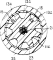
Figure 16 A-C represents the 4th kind of embodiment of optical cable of the present invention.Figure 16 A is the sectional drawing (being equivalent to Figure 1B a-a line section part) 13 1 flip portion theres of groove, Figure 16 B is the sectional drawing (being equivalent to Figure 1B f-f line section part) of the central portion office between groove 13 flip portion, and Figure 16 C is the sectional drawing (being equivalent to Figure 1B k-k line section part) at groove 13 another flip portion places.
This optical cable is on trough of belt lining 11 in formed many SZ spiral slots 13, and a part of groove holds ribbon fiber 15, is holding single-core fiber 35 in another part groove, the jelly of filling simultaneously 37.
Trough of belt lining 11 is a tygon extrusion modling body, and there is tension element 21 center.Trough of belt lining 11 external diameter 15.6mm.The cross dimensions of groove 13: the bottom land width is groove width 2.4mm groove depth 3.4mm with the 1st, 4,5,6 groove that groove upper end width equates; Groove upper end width 2nd, 3 groove bigger than bottom land width is the wide 2.0mm of bottom land, groove upper end wide 4.3mm, groove depth 3.4mm.The flip angle θ of groove 13 is about 280 °, and upset pitch P is about 250mm.
1st, 4 grooves 13 are equipped with 3 ribbon fibers 15 that become layered laminate; 2nd, 3 grooves 13 are equipped with the 4th single-core fiber 35, the jelly of filling simultaneously 37.Ribbon fiber 15 is housed in the groove 13, and is such shown in Figure 16 B, the middle body between groove 13 flip portion, and zone face is towards bottom land; Like that, at the flip portion place, the fibre ribbon side becomes heeling condition towards bottom land shown in Figure 16 A, C.Each ribbon optical fiber 15 all is placed in the groove 13 with the state that is not subjected to tension force.In addition, coding 23 is a clamping cylinder, and coding 25 is an oversheath.
As Figure 10 A those shown, each ribbon fiber 15 is added with common coverture 29 on 4 core fibres 27, and its cross dimensions is wide to be 1.1mm, thick 0.4mm.The cross dimensions of 3 ribbon optical fiber, 15 duplexers is shown in Figure 10 C.Single-core fiber 35 is the nylon covering thread of external diameter 0.9mm.
Manufacture experimently above-mentioned optical cable, ribbon fiber 15 and single-core fiber 35 be installed in trough of belt lining 11, at bag with 23 stages of clamping cylinder with in addition 25 stages of oversheath are measured the loss of each optical fiber.Measuring wavelength X is 1.55 μ m.
As a result, the ribbon fiber loss is: at " bag is with the clamping cylinder stage " average 0.22dB/Km, minimum 0.20dB/Km, maximum 0.24dB/Km; At " oversheath stage " average 0.23dB/Km, minimum 0.21dB/Km, maximum 0.24dB/Km in addition.The loss of single-core fiber is: at " bag is with the clamping cylinder stage " average 0.21dB/Km, minimum 0.20dB/Km, maximum 0.21dB/Km; At " oversheath stage " average 0.22dB/Km, minimum 0.21dB/Km, maximum 0.23dB/Km in addition.Be enough to confirm that this optical cable also has pure performance.
In view of the characteristics of groove, when single-core fiber being placed in the SZ spiral slot, its laying state is played pendulum, but the single-core fiber of present embodiment not only is placed in the groove, also jelly in filling, can make single-core fiber be in semifixed state, and obtain the optical cable of stable performance.The 5th kind of embodiment
Figure 17 A to 17C represents the 5th kind of embodiment of optical cable of the present invention.Figure 17 A is the sectional drawing (being equivalent to Figure 1B a-a line section part) at 13 1 flip portion places of groove, Figure 17 B is the sectional drawing (being equivalent to Figure 1B f-f line section part) of the central portion office between 13 1 flip portion of groove, and Figure 17 C is the sectional drawing (being equivalent to Figure 1B k-k line section part) at groove 13 another flip portion places.
This optical cable has been installed in ribbon fiber 15 in many SZ spiral slots 13 that form on trough of belt lining 11, be filled with jelly 37 simultaneously.Such cable configuration has abundant inhibition because the effect of the motility in the jelly institute electroluminescence cable.The 6th kind of embodiment
Because the tension force when setting up in the optical cable will make its influence not involve optical fiber, it then is effective making ribbon fiber 15 in the SZ spiral slot that unnecessary length be arranged along its length.
Make ribbon fiber 15 that unnecessary length be arranged, will as shown in Figure 18 the possibility that makes ribbon fiber 15 generations that are in the SZ spiral slot 13 as the sample that crawls " periodically warpage (fluctuating) " be arranged.If the fluctuating of ribbon fiber 15 is evenly to take place along its length in the SZ spiral slot 13, then the ribbon fiber 15 in the groove 13 can be similar to and depict sinusoidal curve as.Here, the pitch of establishing the sinusoidal curve of fluctuating is Pa, and the amplitude of fluctuating is a, and groove 13 central axial direction are X-axis, then rises and falls with the following formula approximate representation:
f(x)=aXSin(2πX/Pa) …(3)
At this moment, the relation of surplus long rate β and fluctuating pitch Pa and relief intensity a can be by the following formula approximate representation:
 The minimum profile curvature radius ρ of fluctuating warpage (calling macroscopical warpage in the following text) is by the following formula approximate representation:
ρ=(Pa/2π)
2/a …(5)
If fibre diameter is d, the abnormal gradient ε of optical fiber that is given birth to by the bending of radius-of-curvature ρ just can be shown by approximate Yuan of following formula:
ε=d/(2ρ) …(6)
When considering long-term reliability, important being will be controlled at below 0.1% because of the abnormal gradient ε of warpage that macroscopical warpage of optical fiber is given birth to.For this reason, answer the unnecessary length of size decision of engagement groove 13.
By (4), (5), (6) three formulas, under the abnormal slope of warpage that macroscopical warpage of surplus long rate β is given birth to was controlled at situation below 0.1%, the maximal value of relief intensity a can be by the following formula approximate representation:
a=(β+0.1)
2/0.16 …(7)
In addition, because the amplitude a that the duplexer (thickness NT) of ribbon fiber 15 will be allowed fluctuating is in groove 13, so must be by the inscribed circle diameter E and the groove depth D of following formula setting slot 13:
D≥E≥2a+NT (mm) …(8)
Therefore, in order to be controlled at below 0.1% giving birth to the abnormal slope of warpage at macroscopical warpage of surplus long rate during by β, can be as the size of following formula (8) setting slot 13.
Have by (7) formula and (8) formula:
D≥E≥{(β+0.1)
2/0.08}+NT (mm)…(9)
Other has
D≥E≥{W
2+(NT)
2}
1/2 (mm)…(1)
When groove be shaped as rectangle the time, groove inscribed circle diameter E equals groove width B, groove width B and groove depth D have the relation of following formula.But shown in Figure 10 C and Figure 10 D, like that, the size example bigger than the width W of ribbon fiber 15 of ribbon fiber 15 duplexers (thickness NT) arranged.
D≥B≥2a+NT (mm)…(10)
Therefore, when surplus long rate is β, for the abnormal slope of warpage that macroscopical warpage is given birth to is controlled at below 0.1%, can be by the size of above-mentioned (10) formula setting slot 13.Derive (11) formula by (7) formula and (10) formula, so the width B of groove 13 and depth D satisfy (2) formula and (11) formula simultaneously.For example, 4 core ribbon fibers 15 (wide W=1.1mm, thick T=0.4mm) are stacked and be placed in the groove 13 with 1 to 5, then obtain groove 13 width B relevant shown in the table 3 and the minimum necessary sized value of depth D with surplus long rate β by (2) formula and (11) formula.Markedness △ person is the value that (2) formula is determined in the table 3, and no △ mark person is the value that (11) formula is determined.
D≥B≥{W
2+(NT)
2}
1/2 (mm)…(2)
D≥B≥{(β+0.1)
2/0.08}+NT (mm)…(11)
[table 3]
| Surplus | 1 layer of | 2 layers of groove | 3 layers of groove | 4 layers of | 5 layers of groove |
| 0.05% 0.10 0.15 0.20 | 1.2mm 1.2 1.2△ 1.6△ | 1.4mm 1.4 1.6△ 2.0△ | 1.6mm 1.7△ 2.0△ 2.4△ | 2.0mm 2.2△ 2.4△ 2.8△ | 2.3mm 2.5△ 2.8△ 3.2△ |
Because the peak load when laying optical cable generally is equivalent to 0.2% elongation deformation load, be higher than 0.2% so wish surplus long rate β.
Have again, under the built on stilts situation of optical cable,, require the capable elongation deformation of light below 0.1% with respect to high temperature, optical cable elongation when wind is arranged.Here, for the elongation of about 0.2% optical cable (high temperature, when wind is arranged),, wish that surplus long rate β is higher than 0.1% for the deformation that makes ribbon fiber 15 is lower than 0.1%.If surplus long rate is more than 0.2%, even then under extreme conditions, optical fiber also can be in and be bordering on undeformed shape, keeps the available characteristic of no loss.The embodiment 1 of the 6th kind of embodiment
Figure 18 illustrates the 6th kind of embodiment introducing unnecessary length, is applicable to Fig. 9 A, Fig. 9 B and equal Figure 19 A, the optical cable of Figure 19 B institute graphic representation.Figure 19 A is the sectional drawing of the middle body 19 between the SZ spiral slot flip portion at Figure 1B f-f line place, and Figure 19 B is the sectional drawing of the SZ spiral slot flip portion 17 at Figure 1B k-k line place.
The trough of belt lining 11 of this optical cable is a tygon extrusion modling body, and there is the tension element 21 of steel strand wires at the center, is with 8 SZ spiral slots 13 outward.
Though 8 the duplexer that two ribbon optical fiber 15 are arranged in 15, the four grooves of a ribbon optical fiber is arranged in article one groove in the groove, and the stacked number of ribbon fiber that is held in each groove is arbitrarily.Shown in Figure 19 A like that, middle body 19 places between groove 13 flip portion, ribbon fiber 15 zone faces are towards bottom land; And it is such shown in Figure 19 B, at flip portion 17 places, the lateral margin that then is fibre ribbon is placed in groove 13 towards bottom land (correctly saying, is to suppose originally to place in the groove towards bottom land with zone face, now with the curved interior fibre ribbon lateral margin on one side of the groove that is arranged in flip portion towards bottom land).Coding 23 expression clamping cylinders, coding 25 expression oversheaths.The embodiment 2 of the 6th kind of embodiment
With three kinds of optical cables shown in the cable configuration trial-production table 4 of Figure 19.
[table 4]

In addition, the left side numeric representation " bottom land is wide " of groove width B in the table 4, the right numeric representation " the groove upper end is wide ".
The groove 13 flip angle θ of any trough of belt substrate 11 are that about 300 ° of upset pitch P are about 240mm in three kinds of optical cables.
Like that, the ribbon fiber of use is under one the situation shown in Figure 10 A, common overlayer 29 in addition on 4 core fibres 27, and cross dimensions is wide 1.1mm, thick 0.4mm.The duplexer cross dimensions of two ribbon optical fiber 15 diagrammatically is illustrated among Figure 10 B.
Manufacture experimently above-mentioned three kinds of optical cables, separately all as shown in Figure 18, the ribbon fiber with unnecessary length is housed in the groove 13 of trough of belt lining, with 23 stages of clamping cylinder and 25 stages of oversheath in addition, measure the loss of each ribbon fiber at bag.Measuring wavelength is 1.55 μ m; The results are shown in Fig. 5 A to showing among the 5C.
[table 5A]
| The trial-production piece number | The groove numbering | Bag is with the clamping cylinder stage | Oversheath stage in | |
| 11 layers of ribbon fiber β=0.10 % | 1 | Average minimax | 0.21dB/Km 0.22 0.20 | 0.22dB/Km 0.22 0.21 |
| 4 | Average minimax | 0.21 0.21 0.20 | 0.22 0.23 0.21 |
[table 5B]
| The trial-production piece number | The groove numbering | Bag is with the clamping cylinder stage | Oversheath stage in | |
| 21 layers of ribbon fiber β=0.15 % | 1 | Average minimax | 0.22dB/Km 0.22 0.21 | 0.22dB/Km 0.23 0.21 |
| 4 | Average minimax | 0.21 0.22 0.20 | 0.23 0.24 0.21 |
[table 5C]
| The trial-production piece number | The groove numbering | Bag is with the clamping cylinder stage | Oversheath stage in addition | |
| 32 layers of ribbon fiber lamination β=0.10 % | 1 | Average minimax | 0.22dB/Km 0.23 0.20 | 0.22dB/Km 0.23 0.21 |
| 4 | Average minimax | 0.22 0.23 0.21 | 0.22 0.23 0.20 |
The mark value of loss on average below 0.25dB/Km, is enough to confirm that the optical cable according to the 6th kind of embodiment has pure performance.The 7th kind of embodiment
Figure 20 A to Figure 20 C represents the 7th kind of embodiment of optical cable of the present invention.Figure 20 A to Figure 20 C is equal to Figure 12 A to Figure 12 C, but Figure 20 A to Figure 20 C introduces unnecessary length.
Figure 20 A is the sectional drawing (being equivalent to Figure 1B a-a line section part) at 13 1 flip portion places of groove, Figure 20 B is the sectional drawing (being equivalent to Figure 1B f-f line section part) of middle body between groove 13 flip portion, and Figure 20 C is the sectional drawing (being equivalent to Figure 1B k-k line section part) at groove 13 another flip portion places.Trough of belt lining 11 is a tygon extrusion modling body, and there is single steel wire tension element 21 at the center, is with 5 SZ type grooves 13 outward.
Shown in Figure 20 B, middle body 19 places between groove 13 flip portion, ribbon fiber 15 zone faces are towards bottom land; And shown in Figure 20 A and 20C, become skewed fibre ribbon side at flip portion 17 places towards bottom land; So be housed in the groove 13.In addition, coding 23 is clamping cylinders, and coding 25 is oversheaths.
According to five kinds of optical cables shown in the cable configuration trial-production table 6 of Figure 20.
[table 6]

The flip angle θ of the groove 13 of the trough of belt lining of all five kinds of optical cables is about 290 °, and upset pitch P is about 250mm.
Manufacture experimently above-mentioned five kinds of optical cables,, all when ribbon fiber being installed in the groove of trough of belt lining 11A, with 23 stages of clamping cylinder and 25 stages of oversheath in addition, measure the loss of each ribbon optical fiber in bag for every kind of optical cable.Measuring wavelength is 1.55 μ m; The results are shown in table 7 to table 11.
[table 7]
| The trial-production piece number | The groove numbering | Bag is with the clamping cylinder stage | Oversheath stage in | |
| 41 layers of ribbon fiber β=0.10 % | 1 | Average minimax | 0.21dB/Km 0.21 0.20 | 0.22dB/Km 0.23 0.21 |
| 2 | Average minimax | 0.21 0.22 0.20 | 0.23 0.24 0.21 | |
| 4 | Average minimax | 0.21 0.22 0.20 | 0.22 0.23 0.21 |
[table 8]
| The trial-production piece number | The groove numbering | Bag is with the clamping cylinder stage | Oversheath stage in addition | |
| 51 layers of ribbon fiber β=0.15 % | 1 | Average minimax | 0.22dB/Km 0.23 0.21 | 0.22dB/Km 0.23 0.21 |
| 2 | Average minimax | 0.22 0.23 0.20 | 0.22 0.22 0.21 | |
| 4 | Average minimax | 0.23 0.24 0.21 | 0.23 0.24 0.21 |
[table 9]
| The trial-production piece number | The groove numbering | Bag is with the clamping cylinder stage | Oversheath stage in addition | |
| 62 layers of ribbon fiber lamination β=0.10 % | 1 | Average minimax | 0.23dB/Km 0.23 0.22 | 0.22dB/Km 0.23 0.21 |
| 2 | Average minimax | 0.21 0.21 0.20 | 0.22 0.23 0.21 | |
| 4 | Average minimax | 0.21 0.22 0.20 | 0.22 0.23 0.20 |
[table 10]
| The trial-production piece number | The groove numbering | Bag is with the clamping cylinder stage | Oversheath stage in addition | |
| 72 layers of ribbon fiber lamination β=0.15 % | 1 | Average minimax | 0.21dB/Km 0.22 0.20 | 0.23dB/Km 0.23 0.22 |
| 2 | Average minimax | 0.21 0.22 0.20 | 0.23 0.24 0.21 | |
| 4 | Average minimax | 0.22 0.22 0.21 | 0.22 0.23 0.21 |
[table .11]
| The trial-production piece number | The groove numbering | Bag is with the clamping cylinder stage | Oversheath stage in addition | |
| 83 layers of ribbon fiber lamination β=0.10 % | 1 | Average minimax | 0.21dB/Km 0.21 0.20 | 0.22dB/Km 0.23 0.21 |
| 2 | Average minimax | 0.21 0.21 0.20 | 0.22 0.22 0.21 | |
| 4 | Average minimax | 0.22 0.22 0.21 | 0.22 0.23 0.21 |
The mark value of loss on average below 0.25dB/Km, is enough to confirm that this optical cable has pure performance.The trial-production example of the 7th kind of embodiment
Then manufacture experimently out two kinds of optical cables shown in the table 12 by the cable configuration of Figure 20.
[table 12]
The flip angle θ of the groove 13 of the trough of belt lining of arbitrary optical cable is about 290 °, and upset pitch P is about 250mm.
Compare with each embodiment noted earlier, the groove width B of the SZ spiral slot 13 of the optical cable of present embodiment is bigger, improved the speed that ribbon fiber falls into the SZ spiral slot 13 of (insertion) trough of belt lining 11, with being the guide plate that ribbon fiber 15 is inserted SZ spiral slot 13.
Manufacture experimently above-mentioned two kinds of optical cables,, in the time of all in the groove that ribbon fiber is placed in the trough of belt lining, with 23 stages of clamping cylinder and 25 stages of oversheath in addition, measure the loss of each ribbon fiber at bag for every kind of optical cable.Measuring wavelength is 1.55 μ m; The results are shown among Figure 13 and the table 14.
[table 13]
| The trial-production piece number | The groove numbering | Bag is with the clamping cylinder stage | Oversheath stage in addition | |
| 91 layers of ribbon fiber β=0.10 % | 1 | Average minimax | 0.21dB/Km 0.22 0.20 | 0.22dB/Km 0.23 0.21 |
| 3 | Average minimax | 0.21 0.22 0.20 | 0.22 0.22 0.21 |
[table 14]
| The trial-production piece number | The groove numbering | Bag is with the clamping cylinder stage | Oversheath stage in addition | |
| 10 1 layers of ribbon fiber β=0.10 % | 1 | Average minimax | 0.22dB/Km 0.22 0.21 | 0.23dB/Km 0.24 0.21 |
| 3 | Average minimax | 0.21 0.21 0.20 | 0.22 0.22 0.21 | |
| 10 2 layers of ribbon fiber lamination β=0.10 % | 2 | Average minimax | 0.22 0.23 0.21 | 0.23 0.23 0.22 |
| 4 | Average minimax | 0.22 0.23 0.20 | 0.22 0.22 0.21 |
The mark value of loss on average below 0.25dB/Km, is enough to confirm that this optical cable has pure performance.The 8th kind to the 11 kind of embodiment
Figure 21 to Figure 24 is illustrated in optical cable of the present invention as the embodiment under the situation of the structure of the self-cradling type optical cable of built on stilts laying usefulness.
Figure 21 represents the 8th kind of embodiment, is that the optical cable that will add Figure 20 A to Figure 20 C of clamping cylinder 23 also adds that therewith common overlayer 37 forms the self-cradling type optical cable along Support Level 35, and the section of described overlayer 37 is 8 fonts substantially.
Figure 22 represents the 9th kind of embodiment, is that the optical cable that will add Figure 15 of clamping cylinder 23 also adds that therewith common overlayer 37 forms the self-cradling type optical cable along Support Level 35, and the section of described overlayer 37 is 8 fonts substantially.
Figure 23 represents the tenth kind of embodiment, be with fastening steel cable 41, along Figure 21 or Support Level 35 shown in Figure 22 Support Level is reeled and to tie on Fig. 9, Figure 11, Figure 12, Figure 13, Figure 15, Figure 16, Figure 17, Figure 19 or optical cable 39 shown in Figure 20, form the self-cradling type optical cable.
Figure 24 represents the 11 kind of embodiment, be on Fig. 9, Figure 11, Figure 12, Figure 13, Figure 15, Figure 16, Figure 17, Figure 19 or optical cable 39 shown in Figure 20, along Figure 21 or Support Level shown in Figure 22 35, in certain intervals compression molding part 43 is set, the two is integrated with optical cable and Support Level, forms the self-cradling type optical cable.
In addition, more than all use in each embodiment the lining that many grooves are arranged as the trough of belt lining, but the trough of belt lining that uses in this, the number of its groove is also unrestricted, such as, even 1 groove can not yet.
Have again, be placed in the ribbon fiber duplexer in the trough of belt lining groove, because ribbon fiber is unfettered to each other, so its layer-by-layer state contains the situation that how much loses original shape.
According to above-mentioned explanation, be added on distortion on the ribbon fiber among the present invention mainly in zone face, and be very little towards the warpage that makes the fibre ribbon lateral margin be subjected to bending direction.Simultaneously, owing to can make ribbon fiber keep unnecessary length, just can suppress the loss of ribbon fiber fully little.Thus, the present invention is real to the practicability aspect of this type optical cable is special contribution.
Claims (18)
1. optical cable, it is made of trough of belt lining and at least one ribbon fiber that is placed in this trough of belt lining groove, be formed continuously to few SZ spiral slot on the periphery of described trough of belt lining along its length, it is characterized in that: expression from a flip portion of the SZ of described trough of belt lining spiral slot to next flip portion, at the flip angle of trough of belt lining circumferencial direction angle of revolution greater than 180 °; The middle body of described ribbon fiber between described SZ spiral slot flip portion sentenced the state of its zone face towards SZ spiral slot bottom land, and at the flip portion place of described groove, if supposition was placed towards the bottom land state with zone face originally,, so described ribbon fiber is placed in the described groove then with the curved interior fibre ribbon lateral margin on one side of the groove that is positioned at flip portion state at this towards bottom land.
2. optical cable as claimed in claim 1, the flip angle that it is characterized in that described SZ spiral slot is in 180 ° to 360 ° scopes.
3. optical cable as claimed in claim 1, when it is characterized in that being placed in multi-ribbon shape optical fiber in the SZ spiral slot, described multi-ribbon shape optical fiber with stacked state by ccontaining; Middle body between described SZ spiral slot flip portion is stacked along the degree of depth of groove, and is then stacked along the Width of groove at the flip portion place of groove.
4. one kind as each described optical cable of claim 1 to 3, it is characterized in that the trough of belt lining the SZ spiral slot cross dimensions by in the groove the circumscribed circle size of dress ribbon fiber duplexer section.
5. one kind as each described optical cable of claim 1 to 3, it is characterized in that ribbon fiber is wide to be W, thick for T, when the lamination number is N, and the groove inscribed circle diameter E of described trough of belt lining and the depth D of groove satisfy following relational expression
D≥E≥{W
2+(NT)
2}
1/2 (mm)
6. one kind as claim 4 or 5 described optical cables, the SZ spiral slot that it is characterized in that the trough of belt lining is a rectangular shape, when ribbon fiber is wide is W, thick for T, when the lamination number is N, and the width B and the depth D of the SZ spiral slot of described trough of belt lining satisfy following relational expression
D≥B≥[W
2+(NT)
2}
1/2 (mm)
7. one kind as each described optical cable of claim 1 to 6, it is characterized in that ribbon fiber has the above optical fiber of 4 cores.
8. an optical cable as claimed in claim 1 is characterized in that described ribbon fiber has unnecessary length along its length, is placed in the described SZ spiral slot.
9. optical cable as claimed in claim 8, when it is characterized in that being placed in multi-ribbon shape optical fiber in the SZ spiral slot, described multi-ribbon shape optical fiber with stacked state by ccontaining; Middle body between described SZ spiral slot flip portion is stacked along the degree of depth of groove, and is then stacked along the Width of groove at the flip portion place of groove.
10. an optical cable as claimed in claim 8 or 9 is characterized in that being W, thick for T, when stacked number is N when ribbon fiber is wide, the cross dimensions of the SZ spiral slot of described trough of belt lining, and promptly the relation of groove inscribed circle diameter E and groove depth D satisfies following formula
D≥E≥{W
2+(NT)
2}
1/2 (mm)
And, when long rate β is stipulated by following formula after the ribbon fiber, promptly
β={ (L-L
o)/L
o} * 100 (%) are L wherein
oBe the trough of belt liner sleeve length,
L is the ribbon fiber length that is housed in the groove,
Then described groove inscribed circle diameter E and groove depth D satisfy following formula
D≥E≥{(β+0.1)
2/0.08}+NT (mm)。
11. an optical cable as claimed in claim 7 is characterized in that when ribbon fiber is wide be W, thick for T, when stacked number is N, each satisfies following formula the groove width B of trough of belt lining and depth D
D≥B≥{W
2+(NT)
2}
1/2 (mm)
And, when long rate β is stipulated by following formula after the ribbon fiber, promptly
β={ (L-L
o)/L
o} * 100 (%) are L wherein
oBe the trough of belt liner sleeve length,
L is the ribbon fiber length that is housed in the groove,
Each satisfies following formula then described groove width B and depth D
D≥B≥{(β+0.1)
2/0.08}+NT (mm)。
12. an optical cable as claimed in claim 11, the section that it is characterized in that described SZ spiral slot are that the bottom land of B is more and more wideer towards opening from described width.
13. an optical cable as claimed in claim 1 is characterized in that described trough of belt lining is directly to form described SZ spiral slot along the cable length direction on a lining.
14. an optical cable as claimed in claim 1 is characterized in that described trough of belt lining is the fan groove parts that each have groove with a plurality of, twisting together in the SZ mode forms around the tension part.
15. an optical cable as claimed in claim 1 is installed in described ribbon fiber in the SZ spiral slot that it is characterized in that having, and is installed in single optical fiber and filling jelly in other SZ spiral slot.
16. an optical cable as claimed in claim 1 is characterized in that described ribbon fiber is installed in described SZ spiral slot by the buffer unit support.
17. an optical cable as claimed in claim 1 is characterized in that being installed in described ribbon fiber in the described SZ spiral slot, and the filling jelly.
18. an optical cable as claimed in claim 1 is characterized in that described trough of belt lining is supported on along on the Support Level of its setting.
Applications Claiming Priority (9)
| Application Number | Priority Date | Filing Date | Title |
|---|---|---|---|
| JP17615394 | 1994-07-06 | ||
| JP176153/94 | 1994-07-06 | ||
| JP176153/1994 | 1994-07-06 | ||
| JP319485/94 | 1994-11-30 | ||
| JP31948594 | 1994-11-30 | ||
| JP319485/1994 | 1994-11-30 | ||
| JP12866695 | 1995-05-26 | ||
| JP128666/95 | 1995-05-26 | ||
| JP128666/1995 | 1995-05-26 |
Publications (2)
| Publication Number | Publication Date |
|---|---|
| CN1116313A CN1116313A (en) | 1996-02-07 |
| CN1062663C true CN1062663C (en) | 2001-02-28 |
Family
ID=27315791
Family Applications (1)
| Application Number | Title | Priority Date | Filing Date |
|---|---|---|---|
| CN95109455A Expired - Lifetime CN1062663C (en) | 1994-07-06 | 1995-07-06 | Optical fiber cable |
Country Status (9)
| Country | Link |
|---|---|
| US (1) | US5638478A (en) |
| EP (1) | EP0691556B1 (en) |
| KR (1) | KR100382218B1 (en) |
| CN (1) | CN1062663C (en) |
| CA (1) | CA2153370A1 (en) |
| DE (1) | DE69514049T2 (en) |
| ES (1) | ES2139782T3 (en) |
| MY (1) | MY113721A (en) |
| TW (1) | TW289803B (en) |
Families Citing this family (17)
| Publication number | Priority date | Publication date | Assignee | Title |
|---|---|---|---|---|
| CA2196454C (en) * | 1995-06-08 | 2005-12-27 | Eiji Konda | Optical fiber cable |
| KR970019133U (en) * | 1995-10-31 | 1997-05-26 | Convex Slot Core Shape of Optical Cable | |
| KR100337699B1 (en) * | 1997-08-14 | 2002-07-18 | 윤종용 | Optical fiber composite ground wire |
| JP2000241685A (en) * | 1999-02-19 | 2000-09-08 | Sumitomo Electric Ind Ltd | Optical cable |
| US6212321B1 (en) | 1999-03-25 | 2001-04-03 | Sumitomo Electric Industries, Ltd. | Optical cable |
| US6795625B1 (en) * | 1999-06-03 | 2004-09-21 | Ube-Nitto Kasei Co., Ltd. | Spacer for optical fiber cable and optical fiber cable using the spacer |
| DE10020912A1 (en) * | 2000-04-28 | 2001-10-31 | Scc Special Comm Cables Gmbh | Cable containing optical transmission elements and method for the production thereof |
| US6466719B2 (en) * | 2001-01-04 | 2002-10-15 | The United States Of America As Represented By The Secretary Of The Navy | Optical temperature sensing arrangement for towed cable |
| US6744955B2 (en) | 2001-06-29 | 2004-06-01 | Alcatel | Buffer tube having a high fiber count ribbon stack packaging configuration and corner cushions |
| US7315678B2 (en) * | 2004-12-13 | 2008-01-01 | California Institute Of Technology | Method and apparatus for low-loss signal transmission |
| NL1033918C2 (en) | 2007-05-31 | 2008-12-02 | Draka Comteq Bv | Cable, as well as use and method for constructing a cable network. |
| CN101943775A (en) | 2009-07-03 | 2011-01-12 | 华为技术有限公司 | Cable and cable system |
| WO2017022531A1 (en) * | 2015-07-31 | 2017-02-09 | 住友電気工業株式会社 | Optical fiber cable |
| US9921380B2 (en) * | 2016-03-22 | 2018-03-20 | Ofs Fitel, Llc | Composite cable |
| WO2018230618A1 (en) * | 2017-06-14 | 2018-12-20 | 住友電気工業株式会社 | Slot-type optical cable |
| JPWO2019059251A1 (en) * | 2017-09-21 | 2020-10-15 | 住友電気工業株式会社 | Fiber optic cable |
| CN110160601B (en) * | 2019-06-24 | 2020-10-09 | 吉林大学 | Plastic optical fiber liquid level sensor with spiral structure |
Family Cites Families (14)
| Publication number | Priority date | Publication date | Assignee | Title |
|---|---|---|---|---|
| US4205899A (en) * | 1978-06-08 | 1980-06-03 | Northern Telecom Limited | Optical cables |
| CA1185468A (en) * | 1981-10-06 | 1985-04-16 | Northern Telecom Limited | Optical cables |
| JPS6153612A (en) * | 1984-08-24 | 1986-03-17 | Nippon Telegr & Teleph Corp <Ntt> | Manufacture of spacer type optical cable |
| US4828352A (en) * | 1985-03-04 | 1989-05-09 | Siecor Corporation | S-Z stranded optical cable |
| JPH01163710A (en) * | 1987-02-25 | 1989-06-28 | Sumitomo Electric Ind Ltd | Optical cable |
| JPH01147511A (en) * | 1987-12-04 | 1989-06-09 | Sumitomo Electric Ind Ltd | Production of grooves spacer |
| JPH01239513A (en) * | 1988-03-19 | 1989-09-25 | Furukawa Electric Co Ltd:The | Production of jelly-packed type optical fiber cable |
| JPH0833509B2 (en) | 1988-09-20 | 1996-03-29 | 三菱電線工業株式会社 | SZ inversion twisted tape type optical fiber cable manufacturing equipment |
| GB8908446D0 (en) * | 1989-04-14 | 1989-06-01 | Bicc Plc | Optical cable |
| DE3913372A1 (en) * | 1989-04-24 | 1990-10-25 | Rheydt Kabelwerk Ag | OPTICAL CABLE |
| GB2233779B (en) * | 1989-07-01 | 1993-05-05 | Stc Plc | Optical fibre cable |
| JPH0455803A (en) | 1990-06-25 | 1992-02-24 | Sumitomo Electric Ind Ltd | Optical fiber cable |
| US5193134A (en) * | 1991-03-08 | 1993-03-09 | Pirelli Cavi S.P.A. | Grooved-core cable for use with ribbon optical fibres and process to make the same |
| JPH05203849A (en) | 1992-01-28 | 1993-08-13 | Mitsubishi Cable Ind Ltd | Self-supporting type cable |
-
1995
- 1995-07-06 US US08/499,046 patent/US5638478A/en not_active Expired - Lifetime
- 1995-07-06 CN CN95109455A patent/CN1062663C/en not_active Expired - Lifetime
- 1995-07-06 ES ES95110585T patent/ES2139782T3/en not_active Expired - Lifetime
- 1995-07-06 CA CA002153370A patent/CA2153370A1/en not_active Abandoned
- 1995-07-06 EP EP95110585A patent/EP0691556B1/en not_active Expired - Lifetime
- 1995-07-06 KR KR1019950019808A patent/KR100382218B1/en not_active IP Right Cessation
- 1995-07-06 TW TW084106966A patent/TW289803B/zh not_active IP Right Cessation
- 1995-07-06 MY MYPI95001889A patent/MY113721A/en unknown
- 1995-07-06 DE DE69514049T patent/DE69514049T2/en not_active Expired - Fee Related
Also Published As
| Publication number | Publication date |
|---|---|
| US5638478A (en) | 1997-06-10 |
| DE69514049D1 (en) | 2000-01-27 |
| TW289803B (en) | 1996-11-01 |
| EP0691556A1 (en) | 1996-01-10 |
| EP0691556B1 (en) | 1999-12-22 |
| MY113721A (en) | 2002-05-31 |
| KR100382218B1 (en) | 2003-07-04 |
| CA2153370A1 (en) | 1996-01-07 |
| CN1116313A (en) | 1996-02-07 |
| ES2139782T3 (en) | 2000-02-16 |
| DE69514049T2 (en) | 2000-05-25 |
Similar Documents
| Publication | Publication Date | Title |
|---|---|---|
| CN1062663C (en) | Optical fiber cable | |
| CN1103058C (en) | Projection television lens system | |
| CN1892279A (en) | Optical imaging system | |
| CN1306304C (en) | Imaging lens | |
| CN1664643A (en) | Zoom lens system | |
| CN1894606A (en) | Collective element and solid-state imaging device | |
| CN1329475A (en) | Interdental brush and production method therefor | |
| CN1918671A (en) | Metal-cladded metal matrix composite wire | |
| CN1359024A (en) | Surface illumination device and making method and LCD device | |
| CN1256807A (en) | Heat dissipating device for transmission line, transmission line with heat dissipating device and method for fitting heat dissipating device to transmission line | |
| CN101069248A (en) | Method for manufacturing superconducting tape wire, superconducting tape wire, and superconducting device | |
| CN1522939A (en) | Flexible substrate storage equipment and flexible substrate storing method | |
| CN1743881A (en) | Optical waveguide device | |
| CN1489259A (en) | Stator of alternating-current generator for vehicle and manufacturing method thereof | |
| CN1181838A (en) | Cathode ray tube and method for mfg. the same | |
| CN1956168A (en) | Manufacturing method of solid-state imaging device and solid-state imaging device | |
| CN1670557A (en) | Optical power monitoring apparatus, optical power monitoring method, and light receiving device | |
| CN1274143A (en) | Liquid crystal displaying component, back reflecting mechanism and liquid crystal displaying device adopting same | |
| CN1183552C (en) | Over head wire | |
| CN101034693A (en) | Semiconductor device and method for manufacturing semiconductor device | |
| CN1791286A (en) | Heating plate and manufacturing method of heating plate | |
| CN1067770C (en) | Wide-angle zoom lens | |
| CN1145057C (en) | Projecting lens | |
| CN1153990C (en) | Optical coupler and method of manufacturing the same | |
| CN1239309A (en) | Fuel assembly |
Legal Events
| Date | Code | Title | Description |
|---|---|---|---|
| C06 | Publication | ||
| PB01 | Publication | ||
| C10 | Entry into substantive examination | ||
| SE01 | Entry into force of request for substantive examination | ||
| C14 | Grant of patent or utility model | ||
| GR01 | Patent grant | ||
| CX01 | Expiry of patent term |
Expiration termination date: 20150706 Granted publication date: 20010228 |
|
| EXPY | Termination of patent right or utility model |