CN106182083B - Robot system and emergency stop processing device - Google Patents
Robot system and emergency stop processing device Download PDFInfo
- Publication number
- CN106182083B CN106182083B CN201610373460.8A CN201610373460A CN106182083B CN 106182083 B CN106182083 B CN 106182083B CN 201610373460 A CN201610373460 A CN 201610373460A CN 106182083 B CN106182083 B CN 106182083B
- Authority
- CN
- China
- Prior art keywords
- emergency stop
- switch
- processing device
- circuit
- robot
- Prior art date
- Legal status (The legal status is an assumption and is not a legal conclusion. Google has not performed a legal analysis and makes no representation as to the accuracy of the status listed.)
- Active
Links
Images


Classifications
-
- B—PERFORMING OPERATIONS; TRANSPORTING
- B25—HAND TOOLS; PORTABLE POWER-DRIVEN TOOLS; MANIPULATORS
- B25J—MANIPULATORS; CHAMBERS PROVIDED WITH MANIPULATION DEVICES
- B25J19/00—Accessories fitted to manipulators, e.g. for monitoring, for viewing; Safety devices combined with or specially adapted for use in connection with manipulators
-
- B—PERFORMING OPERATIONS; TRANSPORTING
- B25—HAND TOOLS; PORTABLE POWER-DRIVEN TOOLS; MANIPULATORS
- B25J—MANIPULATORS; CHAMBERS PROVIDED WITH MANIPULATION DEVICES
- B25J9/00—Programme-controlled manipulators
- B25J9/16—Programme controls
- B25J9/1674—Programme controls characterised by safety, monitoring, diagnostic
-
- B—PERFORMING OPERATIONS; TRANSPORTING
- B25—HAND TOOLS; PORTABLE POWER-DRIVEN TOOLS; MANIPULATORS
- B25J—MANIPULATORS; CHAMBERS PROVIDED WITH MANIPULATION DEVICES
- B25J9/00—Programme-controlled manipulators
- B25J9/0081—Programme-controlled manipulators with master teach-in means
-
- G—PHYSICS
- G05—CONTROLLING; REGULATING
- G05B—CONTROL OR REGULATING SYSTEMS IN GENERAL; FUNCTIONAL ELEMENTS OF SUCH SYSTEMS; MONITORING OR TESTING ARRANGEMENTS FOR SUCH SYSTEMS OR ELEMENTS
- G05B19/00—Programme-control systems
- G05B19/02—Programme-control systems electric
- G05B19/42—Recording and playback systems, i.e. in which the programme is recorded from a cycle of operations, e.g. the cycle of operations being manually controlled, after which this record is played back on the same machine
- G05B19/425—Teaching successive positions by numerical control, i.e. commands being entered to control the positioning servo of the tool head or end effector
-
- G—PHYSICS
- G05—CONTROLLING; REGULATING
- G05B—CONTROL OR REGULATING SYSTEMS IN GENERAL; FUNCTIONAL ELEMENTS OF SUCH SYSTEMS; MONITORING OR TESTING ARRANGEMENTS FOR SUCH SYSTEMS OR ELEMENTS
- G05B2219/00—Program-control systems
- G05B2219/30—Nc systems
- G05B2219/36—Nc in input of data, input key till input tape
- G05B2219/36162—Pendant control box
-
- G—PHYSICS
- G05—CONTROLLING; REGULATING
- G05B—CONTROL OR REGULATING SYSTEMS IN GENERAL; FUNCTIONAL ELEMENTS OF SUCH SYSTEMS; MONITORING OR TESTING ARRANGEMENTS FOR SUCH SYSTEMS OR ELEMENTS
- G05B2219/00—Program-control systems
- G05B2219/30—Nc systems
- G05B2219/39—Robotics, robotics to robotics hand
- G05B2219/39447—Dead man switch
-
- G—PHYSICS
- G05—CONTROLLING; REGULATING
- G05B—CONTROL OR REGULATING SYSTEMS IN GENERAL; FUNCTIONAL ELEMENTS OF SUCH SYSTEMS; MONITORING OR TESTING ARRANGEMENTS FOR SUCH SYSTEMS OR ELEMENTS
- G05B2219/00—Program-control systems
- G05B2219/30—Nc systems
- G05B2219/50—Machine tool, machine tool null till machine tool work handling
- G05B2219/50198—Emergency stop
-
- Y—GENERAL TAGGING OF NEW TECHNOLOGICAL DEVELOPMENTS; GENERAL TAGGING OF CROSS-SECTIONAL TECHNOLOGIES SPANNING OVER SEVERAL SECTIONS OF THE IPC; TECHNICAL SUBJECTS COVERED BY FORMER USPC CROSS-REFERENCE ART COLLECTIONS [XRACs] AND DIGESTS
- Y10—TECHNICAL SUBJECTS COVERED BY FORMER USPC
- Y10S—TECHNICAL SUBJECTS COVERED BY FORMER USPC CROSS-REFERENCE ART COLLECTIONS [XRACs] AND DIGESTS
- Y10S901/00—Robots
- Y10S901/02—Arm motion controller
- Y10S901/03—Teaching system
Landscapes
- Engineering & Computer Science (AREA)
- Robotics (AREA)
- Mechanical Engineering (AREA)
- Automation & Control Theory (AREA)
- Physics & Mathematics (AREA)
- Manipulator (AREA)
- General Physics & Mathematics (AREA)
- Numerical Control (AREA)
- Artificial Intelligence (AREA)
- Evolutionary Computation (AREA)
- Fuzzy Systems (AREA)
- Mathematical Physics (AREA)
- Software Systems (AREA)
Abstract
The invention provides a robot system capable of detaching a teaching device from a control device at a place far away from the control device. A robot system is provided with: a robot; a control device for controlling the robot; a teaching device which has a first operation unit for urgently stopping the operation of the robot and which teaches the operation of the robot; and an emergency stop processing device having a second operation unit for continuing the operation of the robot after the first operation unit is operated, the second operation unit being separate from the control device.
Description
Technical Field
The present invention relates to a robot system and an emergency stop processing device.
Background
Teaching devices (e.g., teaching suspensions; TPs) for teaching operations to robots are often used in the field where the robots are to perform work. Such a teaching device is provided with an emergency stop button for emergency stop of the robot. At this time, when the teaching device is detached from the robot, the emergency stop circuit is cut off, and an emergency stop error occurs. In case of an emergency stop error, the peripheral devices connected to the robot have to be restarted.
On the other hand, in a field where a robot performs a task, teaching operations to a plurality of robots using one teaching device is often performed. In this case, the user must repeatedly attach and detach the teaching device to and from the robot.
In contrast, an industrial robot is known which includes an emergency stop cancellation switch that does not cause an emergency stop error even when a teaching device is removed (see patent document 1).
Patent document 1: japanese re-publication of PCT publication No. WO95/09718
However, in the conventional industrial robot, the control device for operating the industrial robot is provided with the emergency stop cancellation switch, and the teaching device cannot be detached without causing an emergency stop error in a place away from the industrial robot. As a result, it is difficult to improve the efficiency of the teaching task performed by the user in the industrial robot.
Disclosure of Invention
In order to solve at least one of the above problems, one embodiment of the present invention is a robot system including: a robot; a control device for controlling the robot; a teaching device which has a first operation unit for urgently stopping the operation of the robot and which teaches the operation of the robot; and an emergency stop processing device including a second operation unit that continues the operation of the robot after the first operation unit is operated, the second operation unit being separate from the control device.
According to this configuration, the robot system makes the operation of the robot suddenly stop by the first operation unit provided in the teaching device, and makes the operation of the robot continue after the first operation unit is operated by the second operation unit provided in the sudden stop processing device, which is the second operation unit separate from the control device. Thus, the robot system can improve the efficiency of teaching tasks.
In addition, other embodiments of the present invention may also use the following structure: in the robot system, the emergency stop processing device may be communicatively connected between the control device and the teaching device.
According to this configuration, in the robot system, the operation of the robot is continued after the first operation unit is operated by the emergency stop processing device communicably connected between the control device and the teaching device. Thus, the robot system can improve the efficiency of the teaching task by using the emergency stop processing device communicably connected between the control device and the teaching device.
In addition, other embodiments of the present invention may also use the following structure: in the robot system, the emergency stop processing device includes a notification unit configured to notify that the second operation unit has been operated.
According to this configuration, the robot system reports that the second operation unit has been operated by the reporting unit. Thus, the robot system can report the operation of the second operation unit to the user through the report unit. As a result, the robot system can prevent the user from detaching the teaching device while the second operation unit is not operated.
In addition, other embodiments of the present invention may also use the following structure: in the robot system, the emergency stop processing device includes a third operation unit for emergency-stopping the operation of the robot.
According to this configuration, the robot system emergently stops the operation of the robot by the third operation unit provided in the emergency stop processing device. Thus, the robot system can make the robot stop urgently even in the state that the teaching device is detached.
In addition, other embodiments of the present invention may also use the following structure: in the robot system, the emergency stop processing device may switch the relay by an operation of the second operation unit.
According to this configuration, the robot system switches the relay by the second operation unit provided in the emergency stop processing device. Thus, the robot system can continue the operation of the robot after the first operation unit is operated based on the switching of the relay by the second operation unit.
In addition, other embodiments of the present invention may also use the following structure: in the robot system, the emergency stop processing device includes a first processor and a second processor that switch the relay.
According to this configuration, the robot system switches the relay using the first processor and the second processor. As a result, the robot system can continue the operation of the robot after the first operation unit is operated as a result of the relay being switched by the first processor and the second processor.
In addition, other embodiments of the present invention may also use the following structure: in the robot system, the first processor and the second processor monitor each other in the emergency stop processing device.
According to this configuration, the robot system causes the first processor to monitor the second processor, and causes the second processor to monitor the first processor. Thereby, the robot system is able to monitor the first processor and the second processor.
In addition, other embodiments of the present invention may also use the following structure: in the robot system, the relay includes a first relay and a second relay, and the emergency stop processing device switches the first relay by the first processor and switches the second relay by the second processor.
According to this configuration, in the robot system, the first relay is switched by the first processor, and the second relay is switched by the second processor. Thereby, the robot system can switch the first relay and the second relay respectively by using different processors.
In addition, other embodiments of the present invention may also use the following structure: in the robot system, the emergency stop processing device includes a plurality of fixing portions for fixing the jig to the emergency stop processing device.
According to this configuration, in the robot system, the jig is fixed to the emergency stop processing device using any one of the plurality of fixing portions. Thus, the robot system can fix the emergency stop processing device by using a fixing part suitable for a fixing place.
Another embodiment of the present invention is directed to an emergency stop processing device including a second operation unit configured to continue an operation of a robot after a first operation unit provided in a teaching device for teaching an operation of the robot, that is, the first operation unit for emergency stop of the operation of the robot is operated, and the second operation unit is separate from a control device for controlling the robot.
According to this configuration, the emergency stop processing device continues the operation of the robot after the first operation unit is operated by the second operation unit that is separate from the control device. Thus, the emergency stop processing device can improve the efficiency of the teaching task.
According to the above configuration, the robot system and the emergency stop processing device continue the operation of the robot after the first operation unit is operated by the second operation unit that is separate from the control device. Thus, the robot system and the emergency stop processing device can improve the efficiency of the teaching task.
Drawings
Fig. 1 is a configuration diagram showing an example of a robot system 1 according to the present embodiment.
Fig. 2 is a diagram showing an example of an external appearance of the emergency stop processing apparatus 50.
Fig. 3 is a diagram showing an example of the configuration of the emergency stop circuit in the robot system 1.
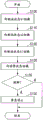
Fig. 4 is a flowchart showing an example of the flow of the fusion detection process performed by the first CPU51 and the second CPU 52.
Fig. 5 is a diagram showing an example of each of three states in which the first CPU51 and the second CPU52 are switched in the fusing detection processing among the states of the switches R1 to R8 provided in the processing device circuit PA and the processing device circuit PB.
Fig. 6 is a schematic diagram showing a state in which the first CPU51 and the second CPU52 perform the fault check processing by using clock signals with each other.
Fig. 7 is a diagram showing an example of an external appearance of the emergency stop processing apparatus 50 and an example of a jig for fixing the emergency stop processing apparatus 50.
Fig. 8 is a diagram illustrating a state in which the jigs G are attached to the emergency stop processing apparatus 50 from three directions.
Detailed Description
Detailed description of the preferred embodiments
Hereinafter, embodiments of the present invention will be described with reference to the drawings. Fig. 1 is a configuration diagram showing an example of a robot system 1 according to the present embodiment. The robot system 1 includes a robot 20, a teaching device 40, and an emergency stop processing device 50. Further, the robot 20 includes a control device 30.
First, the connection between the respective components in the robot system 1 shown in fig. 1 will be described.
In the robot system 1, the control device 30 and the emergency stop processing device 50 are connected to be able to communicate with each other via a cable C1. In the robot system 1, the emergency stop processing device 50 and the teaching device 40 are connected to be able to communicate with each other via a cable C2. That is, in the robot system 1, the emergency stop processing device 50 is communicably connected between the control device 30 and the teaching device 40. The wired communication via the cable C1 and the cable C2 is performed in accordance with specifications such as ethernet (registered trademark) and usb (universal Serial bus).
The control device 30 may be connected to the emergency stop processing device 50 by wireless communication according to a communication standard such as Wi-Fi (registered trademark). The teaching device 40 may be connected to the emergency stop processing device 50 by wireless communication according to a communication standard such as Wi-Fi (registered trademark). However, in the robot system 1, since there is a case where the user makes the robot 20 stop urgently via the teaching device 40 and the emergency stop processing device 50, when the wireless communication is unstable, it is desirable that the communication via the cable C1 and the cable C2 be wired communication.
Next, each configuration of the robot system 1 will be described.
Robot 20 is a two-arm robot including control device 30. A two-arm robot is a robot having two arms (arms). Each arm is made up of an end effector, a robot, and a plurality of actuators. The robot 20 may be a single-arm robot, a parallel robot, an orthogonal-axis robot, a single-axis robot, or a SCARA robot, in addition to a two-arm robot. A single-arm robot is a robot having one arm.
Each actuator is communicably connected to a control device 30 built in the robot 20 via a cable. Thus, the actuator can operate the end effector and the robot based on the control signal acquired from the control device 30. The wired communication via the cable is performed according to specifications such as ethernet (registered trademark) and USB. Some or all of the actuators may be connected to the control device 30 by wireless communication according to a communication standard such as Wi-Fi (registered trademark). In addition to the configuration in which robot 20 incorporates control device 30, robot 20 may be configured to be controlled by control device 30 provided outside, that is, control device 30 separate from robot 20.
The emergency stop circuit is a circuit realized in a state where the control device 30 is connected to the emergency stop processing device 50 via the cable C1, and in a state where the emergency stop processing device 50 is connected to the teaching device 40 via the cable C2. The predetermined portion of the path constituting the emergency stop circuit is, for example, a path that the control device 30 has in a portion of the path constituting the emergency stop circuit. The predetermined portion of the path constituting the emergency stop circuit may be another path of the portion of the path constituting the emergency stop circuit. That is, in the robot system 1, when any one of the cable C1, the emergency stop processing device 50, the cable C2, and the teaching device 40 is detached from the control device 30, and thus the current does not flow through a predetermined portion of the path constituting the emergency stop circuit any more, the control device 30 emergently stops the robot 20.
In the robot system 1, in a state where the control device 30 is connected to the emergency stop processing device 50 via the cable C1 and in a state where the emergency stop processing device 50 is connected to the teaching device 40 via the cable C2, not only the configuration of realizing one emergency stop circuit but also the configuration of realizing two or more emergency stop circuits may be adopted. Hereinafter, a case where there are two emergency stop circuits in the robot system 1 will be described as an example. Therefore, hereinafter, one emergency stop circuit will be referred to as an emergency stop circuit a, and the other emergency stop circuit will be referred to as an emergency stop circuit B. In the following description, the emergency stop circuit a and the emergency stop circuit B will be collectively referred to as an emergency stop circuit when there is no need to distinguish between them.
When the robot system 1 includes two emergency stop circuits, the control device 30 causes the robot 20 to be in emergency stop when the state of one of the emergency stop circuit a and the emergency stop circuit B changes from the energized state to the non-energized state. This is because: from the viewpoint of safety, it is desirable that control device 30 urgently stops robot 20 when the state of either one of emergency stop circuit a and emergency stop circuit B changes from the energized state to the non-energized state. Instead of the above configuration, control device 30 may be configured as follows: when both the emergency stop circuit a and the emergency stop circuit B change their states from the energized state to the non-energized state, the robot 20 is brought to an emergency stop.
The emergency stop releasing unit switches the operation mode of the control device 30 to an operation mode in which the robot 20 is not brought into an emergency stop, even when the state of the emergency stop circuit is changed from the energized state to the non-energized state, based on an operation received from the user. For example, when a first emergency stop release button provided on the front surface of control device 30 is pressed, the emergency stop release unit switches the operation mode of control device 30 to an operation mode in which robot 20 is not emergently stopped.
Teaching device 40 provides a User with an Interface capable of teaching (storing) information indicating the operation of robot 20 to control device 30 via a GUI (Graphical User Interface) implemented by a dedicated application program. Teaching device 40 teaches information indicating the operation of robot 20 to control device 30 based on the operation received from the user via the GUI. Further, the teaching device 40 includes a jog mechanism that performs jog operation of the robot 20. The jog mechanism may be provided in a hardware function section such as a button of the teaching device 40, or may be provided in a software function section provided to a user from a GUI of the teaching device 40.
Further, the teaching device 40 includes a first emergency stop button for changing the state of the emergency stop circuit from an energized state to a non-energized state. For convenience of description, a path included in the teaching device 40 in a part of a path constituting the emergency stop circuit a is referred to as a teaching device circuit TA, and a path included in the teaching device 40 in a part of a path constituting the emergency stop circuit B is referred to as a teaching device circuit TB. In addition, when it is not necessary to distinguish the teaching device circuit TA from the teaching device circuit TB, they will be collectively referred to as a teaching device circuit. The teaching device circuit TA and the teaching device circuit TB each include at least one switch corresponding to the first emergency stop button. When the first emergency stop button is pressed, the teaching device 40 switches the state of the switch to off, and changes the states of the emergency stop circuit a and the emergency stop circuit B from an energized state to a non-energized state. Thus, teaching device 40 can cause control device 30 to stop robot 20 in an emergency. The first emergency stop button is an example of the first operation unit. In the present embodiment, the on state of the switch is a state in which the switch is closed, and the off state of the switch is a state in which the switch is open.
The emergency stop processing device 50 includes a second emergency stop button for emergency stop of the robot 20. For convenience of description, a path included in the emergency stop processing device 50 in a part of the path constituting the emergency stop circuit a will be referred to as a processing device circuit PA, and a path included in the emergency stop processing device 50 in a part of the path constituting the emergency stop circuit B will be referred to as a processing device circuit PB. Note that, when it is not necessary to distinguish between the processing device circuit PA and the processing device circuit PB, they will be collectively referred to as a processing device circuit. The processing device circuit PA and the processing device circuit PB each include at least one switch corresponding to the second emergency stop button. When the second emergency stop button is pressed, the emergency stop processing device 50 switches the state of the switch to off, and changes the states of the emergency stop circuit a and the emergency stop circuit B from the energized state to the non-energized state. Thereby, emergency stop processing device 50 can cause control device 30 to emergency stop robot 20. The second emergency stop button is an example of the third operation unit.
The emergency stop processing device 50 includes a second emergency stop release button that can keep the state of the emergency stop circuit in an energized state even when the connection between the emergency stop processing device 50 and the teaching device 40 is disconnected (for example, when the cable C2 is detached from the emergency stop processing device 50, when the teaching device 40 is detached from the cable C2, or the like), or when the first emergency stop button of the teaching device 40 is pressed.
The processing device circuit PA and the processing device circuit PB each include at least one switch corresponding to the second emergency stop release button. The switch connects a path on the positive side extending toward the control device 30 in the processing device circuit and not included in the cable C2, and a path on the negative side extending toward the control device 30 in the processing device circuit and not included in the cable C2. Thus, even when the cable C2 is detached from the emergency stop processing device 50, the teaching device 40 is detached from the cable C2, or the first emergency stop button of the teaching device 40 is pressed, the state of the emergency stop circuit can be kept unchanged. Hereinafter, a case where the state of the emergency stop circuit is kept in the energized state by pressing at least one of the first emergency stop release button and the second emergency stop release button will be referred to as release of the emergency stop. The second emergency stop release button is an example of the second operation unit.
Here, the appearance of the emergency stop processing apparatus 50 will be described with reference to fig. 2. Fig. 2 is a diagram showing an example of an external appearance of the emergency stop processing apparatus 50. As shown in fig. 2, the emergency stop processing device 50 includes a second emergency stop release button B1, a second emergency stop button B2, a display unit L1, and a display unit L2.
The display unit L1 is provided on the surface of the second emergency stop release button B1. The display unit L1 displays that the second emergency stop release button B1 is pressed, that is, the emergency stop is released. The display unit L1 is an led (light Emitting diode) in this example. The display unit L1 indicates that the second emergency stop release button B1 is pressed by the lighted light. Note that the display unit L1 may be an LED, a display for displaying characters and symbols, or the like, in which the second emergency stop release button B1 is pressed. The emergency stop processing device 50 may include other functional units such as a speaker and a vibrating unit for vibrating the emergency stop processing device 50, in addition to the display unit L1. When the speaker is provided, the emergency stop processing device 50 notifies the user that the second emergency stop release button B1 is pressed by a sound from the speaker. The display unit L1 is an example of a report unit.
Display unit L2 indicates that the state of the emergency stop circuit has changed from the energized state to the non-energized state, that is, that robot 20 has been brought to an emergency stop. The display portion L2 is an LED in this example. The display unit L2 indicates, by the lighted light, that the state of the emergency stop circuit has changed from the energized state to the non-energized state. For example, when the second emergency stop button B2 is pressed while the second emergency stop release button B1 is not pressed, the display unit L2 turns on the light because the state of the emergency stop circuit changes from the energized state to the non-energized state. In addition to the LED, the display unit L2 may be a display or the like that displays a change in the state of the emergency stop circuit from an energized state to a non-energized state by displaying characters and symbols. The emergency stop processing device 50 may include other functional units such as a speaker and a vibrating unit for vibrating the emergency stop processing device 50, in addition to the display unit L2. When a speaker is provided, the emergency stop processing device 50 notifies the user of a change in the state of the emergency stop circuit from the energized state to the non-energized state by a sound from the speaker.
Further, the emergency stop processing device 50 can freely change the setting position by changing the lengths of the cable C1 and the cable C2. That is, the emergency stop processing device 50 can be installed in the vicinity of a work place where a user uses the teaching device 40 to perform work. By providing the emergency stop processing device 50 separately from the control device 30 in this way, the teaching device 40 can be detached from the robot system 1 by pressing the second emergency stop release button B1 at a location remote from the control device 30, while maintaining the state of the emergency stop circuit in the energized state. As a result, the robot system 1 can improve the efficiency of the teaching task.
For example, when information indicating an operation is taught to the control device 30 incorporated in each of the plurality of robots 20 by one teaching device 40, the robot system 1 improves the efficiency of teaching work. In this case, when detaching the teaching device 40 from the first robot 20 and connecting the teaching device 40 to the second robot 20, the teaching device 40 can be detached from the first robot 20 without moving the control device 30 to an operable place in order to press a first emergency stop release button provided on the surface of the control device 30 of the first robot 20.
Further, the emergency stop processing device 50 includes the display unit L1, and thereby the robot system 1 can visually notify the user whether or not the current state is a state in which the robot 20 can be stopped urgently (whether or not the second emergency stop release button B1 is pressed). As a result, the robot system 1 can suppress the robot 20 from continuing to operate in a state where the user has inadvertently pressed the second emergency stop release button B1.
Further, the emergency stop processing device 50 includes the second emergency stop button B2, and thus the robot system 1 can emergency stop the robot 20 by pressing the second emergency stop button B2 even when the user is located at a place distant from the control device 30 or the teaching device 40. As will be described later, even when the second emergency stop release button B1 is pressed when the second emergency stop button B2 is pressed, the emergency stop processing device 50 can cause the control device 30 to emergency stop the robot 20 without releasing the emergency stop of the robot 20.
As described above, in the robot system 1, the second emergency stop release button B1 of the emergency stop processing device 50 is pressed (operated), and thus even when the first emergency stop button is pressed, the state of the emergency stop circuit can be kept in the energized state. A specific example of the structure of the emergency stop circuit in the robot system 1 will be described below.
Specific example of the structure of the emergency stop circuit in the robot system 1
A specific example of the configuration of the emergency stop circuit in the robot system 1 will be described below with reference to fig. 3 to 5. Fig. 3 is a diagram showing an example of the configuration of the emergency stop circuit in the robot system 1. Fig. 3(a) shows an example of the structure of the emergency stop circuit a. Fig. 3(B) shows an example of the structure of the emergency stop circuit B.
As described above, when the state of either one of the emergency stop circuit a and the emergency stop circuit B changes from the energized state to the non-energized state, the control device 30 causes the robot 20 to be brought into an emergency stop. In other words, the emergency stop circuit a is a backup for the emergency stop circuit B when it fails, and the emergency stop circuit B is a backup for the emergency stop circuit a when it fails. Thus, in the robot system 1, even when the state of either one of the emergency stop circuit a and the emergency stop circuit B cannot be changed from the energized state to the non-energized state due to a failure, the control device 30 can cause the robot 20 to be suddenly stopped by changing the state of the non-failed one from the energized state to the non-energized state.
As shown in fig. 3(a), the emergency stop circuit a is configured as follows: the path X1 included in the control device 30 among the paths constituting the emergency stop circuit a is connected to the processing device circuit PA via a cable C1, and the processing device circuit PA is connected to the teaching device circuit TA via a cable C2. In fig. 3(a), details of the path X1 are omitted to simplify the drawing.
Hereinafter, a path extending from the positive electrode side of the control device 30 ((+)) to the switch TA1 provided in the teaching device circuit TA in the processing device circuit PA will be referred to as a path PL 1. Hereinafter, a path extending from the negative side ((-) shown in fig. 3 a) of the control device 30 to the switch TA1 provided in the teaching device circuit TA in the processing device circuit PA will be referred to as a path NL 1.
In the path PL1, a switch PA1 and a parallel circuit PC1 are provided in this order from the control device 30 side toward the teaching device 40 side. The parallel circuit PC1 branches the path PL1 into two paths and joins them again into one path just before proceeding from the emergency stop processing device 50 to the cable C2. The parallel circuit PC1 is provided with a switch R1 on one of the branched paths V1. In the parallel circuit PC1, a switch R2 is provided on the other branched path V2. Further, a path SC1 connecting the path PL1 and the path NL1 is provided between the switch PA1 and the parallel circuit PC 1. Two switches, i.e., a switch R3 and a switch R4, are provided in series on the path SC 1.
The switch TA1 provided in the teaching device circuit TA is a switch corresponding to the first emergency stop button provided in the teaching device 40. That is, the state of switch TA1 is switched to off by pressing the first emergency stop button. The switch PA1 provided on the path PL1 corresponds to the second emergency stop button B2 provided in the emergency stop processing device 50. That is, the state of the switch PA1 is switched to off by pressing the second emergency stop button B2. In the emergency stop circuit a shown in fig. 3(a), the three switches, i.e., the switch R1, the switch R3, and the switch R4, are off, and the switch R2 is on. The states of these switches in the emergency stop circuit a are the states shown in fig. 3(a) in the initial state.
When the state of the switch TA1 is switched off in this initial state, the emergency stop circuit a is no longer a closed circuit, and therefore the state of the emergency stop circuit a changes from the energized state to the non-energized state. Thus, teaching apparatus 40 causes control apparatus 30 to urgently stop robot 20 when the first emergency stop button is pressed. When the state of the switch PA1 is switched off in the initial state of the emergency stop circuit a, the emergency stop circuit a is no longer a closed circuit, and therefore the state of the emergency stop circuit a changes from the energized state to the non-energized state. Thus, when the second emergency stop button B2 is pressed, the emergency stop processing device 50 causes the control device 30 to emergency stop the robot 20.
The switches R3 and R4 correspond to the second emergency stop release button B1 of the emergency stop processing device 50. That is, the states of both the switch R3 and the switch R4 are switched on by pressing the second emergency stop release button B1. When the state of the switch TA1 is switched off in this state, the path PL1 and the path NL1 are connected to the path SC1, and therefore the state of the emergency stop circuit a remains in the energized state. Thus, when the second emergency stop release button B1 is pressed, the emergency stop processing device 50 releases the emergency stop of the robot 20 achieved by the pressing of the first emergency stop button.
Even when both the state of the switch R3 and the state of the switch R4 are switched on by pressing the second emergency stop release button B1, the state of the switch PA1 is switched off when the second emergency stop button B2 is pressed, and therefore the emergency stop circuit a is no longer a closed circuit. Thereby, the state of the emergency stop circuit B is changed from the energized state to the non-energized state. That is, as described above, even when the second emergency stop release button B1 is pressed, the emergency stop processing device 50 can cause the control device 30 to emergency stop the robot 20 when the second emergency stop button B2 is pressed.
The switch corresponding to the second emergency stop release button B1 may be either one of the switch R3 and the switch R4. In this case, when the second emergency stop release button B1 is pressed in a state where the switch not corresponding to the second emergency stop release button B1 is on, the emergency stop processing device 50 can release the emergency stop of the robot 20 by the pressing of the first emergency stop button.
In the emergency stop circuit a, the switches R1 and R2, and the switches R3 and R4 are used to check whether the switches R3 and R4 are not blown. The processing related to this examination will be described later.
As shown in fig. 3(B), the emergency stop circuit B is configured as follows: among the paths constituting the emergency stop circuit B, the path X2 included in the control device 30 is connected to the processing device circuit PB via a cable C1, and the processing device circuit PB is connected to the teaching device circuit TB via a cable C2. In fig. 3(B), details of the path X2 are omitted to simplify the drawing.
Hereinafter, a path extending from the positive electrode side of the control device 30 ((+)) to the switch TB1 provided in the teaching device circuit TB in the processing device circuit PB will be referred to as a path PL 2. Hereinafter, a path extending from the negative side ((-) shown in fig. 3B) of the control device 30 to the switch TB1 provided in the teaching device circuit TB in the processing device circuit PB will be referred to as a path NL 2.
In path PL2, switch PB1 and parallel circuit PC2 are provided in this order from the control device 30 side toward the teaching device 40 side. The parallel circuit PC2 branches the path PL2 into two paths and joins them again into one path just before proceeding from the emergency stop processing device 50 to the cable C2. The parallel circuit PC2 is provided with a switch R5 on one of the branched paths V3. In the parallel circuit PC2, a switch R6 is provided on the other branched path V4. Further, a path SC2 connecting the path PL2 and the path NL2 is provided between the switch PB1 and the parallel circuit PC 2. Two switches, i.e., a switch R7 and a switch R8, are provided in series on the path SC 2.
The switch TB1 provided in the teaching device circuit TB represents a switch corresponding to the first emergency stop button provided in the teaching device 40. That is, the state of the switch TB1 is switched to off by pressing the first emergency stop button. The switch PB1 provided on the path PL2 represents a switch corresponding to the second emergency stop button B2 provided in the emergency stop processing device 50. That is, the state of the switch PB1 is switched to off by pressing the second emergency stop button B2. In the emergency stop circuit B shown in fig. 3(B), the three switches, i.e., the switch R5, the switch R7, and the switch R8, are off, and the switch R6 is on. The states of these switches in the emergency stop circuit B are the states shown in fig. 3(B) in the initial state.
When the state of switch TB1 is switched off in this initial state, emergency stop circuit B is no longer a closed circuit, and therefore the state of emergency stop circuit B changes from the energized state to the non-energized state. Thus, teaching apparatus 40 causes control apparatus 30 to urgently stop robot 20 when the first emergency stop button is pressed. When the state of the switch PB1 is switched to off in the initial state of the emergency stop circuit B, the emergency stop circuit B is no longer a closed circuit, and therefore the state of the emergency stop circuit B changes from the energized state to the non-energized state. Thus, when the second emergency stop button B2 is pressed, the emergency stop processing device 50 causes the control device 30 to emergency stop the robot 20.
The switches R7 and R8 are switches corresponding to the second emergency stop release button B1 provided in the emergency stop processing device 50. That is, the states of both the switch R7 and the switch R8 are switched on by pressing the second emergency stop release button B1. When the state of the switch TB1 is switched off in this state, the path PL2 and the path NL2 are connected to the path SC2, and therefore the state of the emergency stop circuit B remains the energized state. Thus, when the second emergency stop release button B1 is pressed, the emergency stop processing device 50 releases the emergency stop of the robot 20 that is achieved by the pressing of the first emergency stop button.
Even when both the switch R7 and the switch R8 are switched on by pressing the second emergency stop release button B1, the switch PB1 is switched off when the second emergency stop button B2 is pressed, and thus the emergency stop circuit B is no longer a closed circuit. Thereby, the state of the emergency stop circuit B is changed from the energized state to the non-energized state. That is, as described above, even when the second emergency stop release button B1 is pressed, the emergency stop processing device 50 can cause the control device 30 to emergency stop the robot 20 when the second emergency stop button B2 is pressed.
The switch corresponding to the second emergency stop release button B1 may be either one of the switch R7 and the switch R8. In this case, when the second emergency stop release button B1 is pressed while the switch not corresponding to the second emergency stop release button B1 is on, the emergency stop processing device 50 can release the emergency stop of the robot 20 by pressing the first emergency stop button.
In the emergency stop circuit B, the switches R5, R6, R7 and R8 are used to check whether the switches R7 and R8 are not blown. The processing related to this examination will be described later.
Fusing detection processing for emergency stop circuit in robot system 1
The following describes a fuse detection process for checking whether or not the switch R3 and the switch R4 provided in the emergency stop circuit a and the switch R7 and the switch R8 provided in the emergency stop circuit B are each not blown.
The switches R1 to R4 shown in fig. 3(a) and the switches R5 to R8 shown in fig. 3(B) are, for example, safety relay switches. These safety relay switches are operated by two CPUs provided in the emergency stop Processing device 50, namely, a first CPU (central Processing unit)51 and a second CPU 52.
Fig. 3(C) shows an example of a safety relay switch operated by the first CPU 51. The first CPU51 operates two safety relay switches, i.e., a switch RS1 and a switch RS 2. The switch RS1 corresponds to the switch R2. When the first CPU51 switches the state of the switch RS1 to on, the state of the switch R2 is switched to off. On the other hand, when the first CPU51 switches the state of the switch RS1 to off, the state of the switch R2 is switched to on. When the state of the switch RS1 is switched on and the state of the switch R2 is not switched off, the first CPU51 determines that the switch R2 is blown (that is, detects the blowing of the switch R2).
The switch RS2 corresponds to the switch R1, the switch R3, and the switch R7. When the first CPU51 switches the state of the switch RS2 to on, the states of the switch R1, the switch R3, and the switch R7 are switched to off. On the other hand, when the first CPU51 switches the state of the switch RS2 to off, the states of the switch R1, the switch R3, and the switch R7 are switched to on.
When the state of the switch RS2 is switched on and the state of the switch R1 is not switched off, the first CPU51 determines that the switch R1 is blown (that is, detects the blowing of the switch R1). When the state of the switch RS2 is switched on and the state of the switch R3 is not switched off, the first CPU51 determines that the switch R3 is blown (that is, detects the blowing of the switch R3). When the state of the switch RS2 is switched on and the state of the switch R7 is not switched off, the first CPU51 determines that the switch R7 is blown (that is, detects the blowing of the switch R7). The first CPU51 is an example of a first processor.
Fig. 3(D) shows an example of a safety relay switch operated by the second CPU 52. The second CPU52 operates two safety relay switches, i.e., a switch RS3 and a switch RS 4. The switch RS3 corresponds to the switch R6. When the second CPU52 switches the state of the switch RS3 to on, the state of the switch R6 is switched to off. On the other hand, when the second CPU52 switches the state of the switch RS3 to off, the state of the switch R6 is switched to on. When the state of the switch RS3 is switched on and the state of the switch R6 is not switched off, the second CPU52 determines that the switch R6 is blown (that is, detects the blowing of the switch R6).
The switch RS4 corresponds to the switch R4, the switch R5, and the switch R8. When the second CPU52 switches the state of the switch RS4 to on, the states of the switch R4, the switch R5, and the switch R8 are switched to off. On the other hand, when the second CPU52 switches the respective states of the switch RS4 to off, the states of the switch R4, the switch R5, and the switch R8 are switched to on.
When the state of the switch RS4 is switched on and the state of the switch R4 is not switched off, the second CPU52 determines that the switch R4 is blown (that is, detects the blowing of the switch R4). When the state of the switch RS4 is switched on and the state of the switch R5 is not switched off, the second CPU52 determines that the switch R5 is blown (that is, detects the blowing of the switch R5). When the state of the switch RS4 is switched on and the state of the switch R8 is not switched off, the second CPU52 determines that the switch R8 is blown (that is, detects the blowing of the switch R8). The second CPU52 is an example of a second processor.
The first CPU51 and the second CPU52 keep the switch R2 and the switch R6 in the on state and keep the switch R1, the switches R3 to R5, the switch R7, and the switch R8 in the off state except for performing the fusion detection processing. This is the same state as the initial state of the emergency stop circuit a and the emergency stop circuit B described above. Hereinafter, for convenience of explanation, the same state as the initial state will be referred to as a normal state. On the other hand, when the first CPU51 and the second CPU52 perform the fusion detection process, for example, the states of the eight switches are changed from the normal state while executing the process of the flowchart shown in fig. 4, and thereby whether or not each of the switch R3, the switch R4, the switch R7, and the switch R8 is not fused is checked. By this check, the first CPU51 and the second CPU52 detect (specify) a blown switch when any one of the switch R3, the switch R4, the switch R7, and the switch R8 is blown.
Fig. 4 is a flowchart showing an example of the flow of the fusion detection process performed by the first CPU51 and the second CPU 52. The first CPU51 and the second CPU52 perform the fusing detection process, for example, every time a predetermined period elapses. The first CPU51 and the second CPU52 perform the fusing detection process while keeping the state of the emergency stop circuit in the energized state. In addition to this configuration, the first CPU51 and the second CPU52 may perform the fusing detection process at other timings, such as performing the fusing detection process each time the control device 30 is activated. Hereinafter, the states of the switches R1 to R8 provided in the processing device circuit PA and the processing device circuit PB before the processing of step S100 is executed will be described as normal states.
The first CPU51 and the second CPU52 switch the states of the switches R1 to R8 provided in the processing device circuit PA and the processing device circuit PB from the normal state to the test state a1 shown in fig. 5B (step S100). Here, the test state a1 will be explained. Fig. 5 is a diagram showing an example of each of three states in which the first CPU51 and the second CPU52 are switched in the fusing detection processing among the states of the switches R1 to R8 provided in the processing device circuit PA and the processing device circuit PB. Here, in fig. 5, the configuration of the processing device circuit PA is the same as that of the processing device circuit PB, and therefore, while showing this configuration, the reference numerals of the processing device circuit PA and the reference numerals of the processing device circuit PB are given to this configuration.
Fig. 5(a) shows an example of a normal state among states of the switches R1 to R8 provided in the processing device circuit PA and the processing device circuit PB. Fig. 5(B) shows an example of the test state a1 among the states of the switches R1 to R8 provided in the processing device circuit PA and the processing device circuit PB.
The normal state shown in fig. 5 a is the same as the initial state (i.e., normal state) shown in fig. 3 among the states of the switches R1 to R8 provided in the processing device circuit PA and the processing device circuit PB, and therefore, the description thereof is omitted. In the test state a1 shown in fig. 5(B), the first CPU51 and the second CPU52 keep the states of the switch RS1 and the switch RS3 off, and switch the states of the switch RS2 and the switch RS4 off. Thus, the first CPU51 and the second CPU52 turn on all of the switches R1 to R8 provided in the processing device circuit PA and the processing device circuit PB.
As preparation for checking whether or not the switch is blown, the first CPU51 and the second CPU52 execute the processing of step S100 to switch the states of the switches R1 to R8 provided in the processing device circuit PA and the processing device circuit PB from the normal state to the test state a 1.
Next, the first CPU51 and the second CPU52 switch the states of the switches R1 to R8 provided in the processing device circuit PA and the processing device circuit PB from the test state a1 to the test state a2 (step S110). Here, referring again to fig. 5, test state a2 will be described. Fig. 5(C) shows an example of the test state a2 among the states of the switches R1 to R8 provided in the processing device circuit PA and the processing device circuit PB.
In a test state a2 shown in fig. 5(C), the first CPU51 and the second CPU52 switch the states of the switch RS1 and the switch RS3 on, and keep the states of the switch RS2 and the switch RS4 off. Thus, the first CPU51 and the second CPU52 switch the states of the switch R2 and the switch R6 among the switches R1 to R8 provided in the processing device circuit PA and the processing device circuit PB to off states.
By switching the states of the switches R1 to R8 provided in the processing device circuit PA and the processing device circuit PB from the test state a1 to the test state a2, the first CPU51 and the second CPU52 can detect whether or not the switches R2 and R6 are blown, respectively. The switch R2 and the switch R6 are safety relay switches as described above. Therefore, when the switch R2 is blown, the first CPU51 can detect that the switch R2 is blown through the processing of steps S100 to S110. In addition, when the switch R6 is blown, the second CPU52 can detect that the switch R6 is blown through the processing of step S100 to step S110.
Next, the first CPU51 and the second CPU52 switch the states of the switches R1 to R8 provided in the processing device circuit PA and the processing device circuit PB from the test state a2 to the test state a1 again (step S120). As preparation for checking whether or not the remaining six safety relay switches other than the switch R2 and the switch R6 are blown, the first CPU51 and the second CPU52 switch the states of the switches R1 to R8 provided in the processing device circuit PA and the processing device circuit PB from the test state a2 to the test state a1 again.
Next, the first CPU51 and the second CPU52 switch the states of the switches R1 to R8 provided in the processing device circuit PA and the processing device circuit PB from the test state a2 to the normal state (step S130). By switching the states of the switches R1 to R8 provided in the processing device circuit PA and the processing device circuit PB from the test state a2 to the normal state, the first CPU51 and the second CPU52 can detect whether or not each of the switches R1, R3 to R5, R7, and R8 is blown.
The switch R1, the switches R3 to R5, the switch R7, and the switch R8 are safety relay switches as described above. Therefore, when any one of the switch R1, the switch R3, and the switch R7 is blown, the first CPU51 can detect the blown switch among the switch R1, the switch R3, and the switch R7 through the processing of steps S100 to S110. When any one of the switch R4, the switch R5, and the switch R8 is blown, the second CPU52 can detect the blown switch among the switch R4, the switch R5, and the switch R8 through the processing of steps S100 to S110.
Next, the first CPU51 and the second CPU52 determine whether or not the switch blown in step S110 and step S130 is detected (step S135). When determining that the switch blown in step S110 and step S130 is detected (step S135 — yes), first CPU51 and second CPU52 cause control device 30 to stop robot 20 in an emergency (step S130). At this time, the first CPU51 and the second CPU52 cause the display unit L2 included in the emergency stop processing device 50 to illuminate light, and the process ends. On the other hand, if it is determined that the blown switch is not detected in step S110 and step S130 (no in step S135), the first CPU51 and the second CPU52 end the process because the blowing (failure) is not generated. A part or all of the switches R1 to R8 are examples of relays. In addition, some or all of the switch R1, the switch R2, the switch R3, and the switch R7, the states of which are switched by the first CPU51, are examples of the first relay. In addition, a part or all of the switch R4, the switch R5, the switch R6, and the switch R8, the states of which are switched by the second CPU52, are an example of the second relay.
As described above, the first CPU51 and the second CPU52 can suppress the inadvertent release of the emergency stop by performing the fuse detection process, and as a result, the safety can be improved. However, if any one of the first CPU51 and the second CPU52 fails in a state where the emergency stop is released, the release of the emergency stop may be continued unintentionally. To suppress this, the first CPU51 and the second CPU52 mutually perform failure check processing for checking whether or not a failure has not occurred. The failure checking process will be described below.
Failure check processing of the first CPU51 and the second CPU52
The first CPU51 included in the emergency stop processing device 50 includes a first timer unit, not shown, for counting time. The first CPU51 continues to transmit a clock signal of a predetermined clock cycle to the second CPU52 based on the time counted by the first timer unit. In addition, the first CPU51 receives clock signals from the second CPU 52. When the clock cycle of the received clock signal changes, the first CPU51 determines that the second CPU52 has failed, and causes the control device 30 to stop the robot 20 in an emergency. Then, the first CPU51 causes the display unit L2 to light up.
The second CPU52 included in the emergency stop processing device 50 includes a second timer unit, not shown, for counting the time. The second CPU52 continues to transmit a clock signal of a predetermined clock cycle to the first CPU51 based on the time counted by the second timer unit. In addition, the second CPU52 receives clock signals from the first CPU 51. When the clock cycle of the received clock signal changes, the second CPU52 determines that the first CPU51 has failed, and causes the control device 30 to stop the robot 20 in an emergency. Then, the second CPU52 causes the display unit L2 to light up.
Fig. 6 is a schematic diagram showing a state in which the first CPU51 and the second CPU52 perform the fault check processing by using clock signals with each other. As shown in fig. 6, the first CPU51 continuously transmits a clock signal SG1 to the second CPU 52. Also, the second CPU52 continuously receives the clock signal SG1 from the first CPU 51. On the other hand, the second CPU52 continuously transmits the clock signal SG2 to the first CPU 51. Also, the first CPU51 continuously receives the clock signal SG2 from the second CPU 52.
Thus, even when one of the first CPU51 and the second CPU52 malfunctions while the emergency stop is released, the first CPU51 and the second CPU52 can suppress the unintentional continuation of the release of the emergency stop.
Emergency stop processing device 50 and mounting jig therefor
Hereinafter, the fixing of the emergency stop processing apparatus 50 to a place where the robot 20 is to perform work, such as a factory, will be described with reference to fig. 7 and 8. Fig. 7 is a diagram showing an example of an external appearance of the emergency stop processing apparatus 50 and an example of a jig for fixing the emergency stop processing apparatus 50. Fig. 7(a) is a plan view of the emergency stop processing apparatus 50 when a surface of the emergency stop processing apparatus 50 on which the second emergency stop release button B1 is provided is defined as an upper surface. The plan view of the emergency stop processing apparatus 50 shown in fig. 7(a) is already described in fig. 2, and therefore, the description thereof is omitted.
Hereinafter, as shown in fig. 7, a surface of the emergency stop processing apparatus 50 provided with the second emergency stop release button B1 will be referred to as a zeroth surface M0. The surface adjacent to the zeroth surface and to which the cables C1 and C2 are attached in the emergency stop processing device 50 will be referred to as a first surface M1. In the following description, when the emergency stop processing device 50 is viewed from the first surface M1 side with the zeroth surface M0 facing upward, a surface adjacent to the left side of the first surface M1 is referred to as a second surface M2, and a surface adjacent to the right side of the first surface M1 is referred to as a third surface. In the following description, a surface of the emergency stop processing apparatus 50 opposite to the first surface is referred to as a fourth surface M4, and a surface opposite to the zeroth surface is referred to as a fifth surface M5.
The second surface M2 and the third surface M3 are provided with four screw holes for fastening screws, respectively. Here, fig. 7(B) is an example of a side view of the emergency stop processing device 50 in a case where the third surface M3 is a side surface. As shown in fig. 7(B), the third surface M3 includes four screw holes T1 to T4. The number of screw holes provided in each of the second surface M2 and the third surface M3 is four, and in addition to this configuration, three or less screw holes may be provided, or five or more screw holes may be provided.
Fig. 7(C) shows an example of a jig for fixing the emergency stop processing apparatus 50 to a floor surface, a wall surface, or the like. Fig. 7(C) shows a jig G for fixing an L-shaped metal plate, for example. The jig G is provided with holes T5 to T8 through which screws are passed. For example, by using the holes T5 to T8 and the screw holes T1 to T4 provided on the third surface M3 of the emergency stop processing apparatus 50, the clip G can be attached to the emergency stop processing apparatus 50 from any one of three directions. For convenience of description, the rear surface of the jig G on which the holes T5 and T6 are provided, out of the surfaces of the jig G on which the holes T7 and T8 are provided, from which the surface of the jig G on which the holes T5 and T6 protrude, will be referred to as a sixth surface M6.
Fig. 8 is a diagram illustrating a state in which the jigs G are attached to the emergency stop processing apparatus 50 from three directions. Fig. 8(a) shows a case where the jig G is attached to the emergency stop processing apparatus 50 in such a manner that the fifth surface M5 is parallel to the sixth surface M6. Fig. 8(B) shows a case where the jig G is attached to the emergency stop processing apparatus 50 such that the fourth surface M4 is parallel to the sixth surface M6. Fig. 8(C) shows a case where the jig G is attached to the emergency stop processing apparatus 50 such that the first surface M1 is parallel to the sixth surface M6. In this way, the emergency stop processing device 50 can attach the jig G at a position suitable for the installation location by selecting any one of the three types of attachment methods shown in fig. 8.
Among the surfaces of the emergency stop processing device 50, the surface to which the jig G can be attached is not limited to the second surface M2 and the third surface M3, and may be another surface. The jig G may be a jig having another shape than the L-shaped metal plate. In addition, a part or all of the screw hole portions T1 to T4 are examples of the fixing portions.
As described above, the robot system 1 according to the modification of the present embodiment urgently stops the operation of the robot by the first operation unit (in this example, the first emergency stop button) provided in the teaching device 40, and continues the operation of the robot 20 after the first operation unit is operated by the second operation unit (in this example, the second emergency stop release button B1) separate from the control device 30, that is, the second operation unit provided in the emergency stop processing device 50. Thus, the robot system 1 can improve the efficiency of teaching tasks.
In the robot system 1, the emergency stop processing device 50 communicably connected between the control device 30 and the teaching device 40 continues the operation of the robot 20 after the first operation unit is operated. Thus, the robot system 1 can improve the efficiency of the teaching task by using the emergency stop processing device 50 communicably connected between the control device 30 and the teaching device 40.
In addition, the robot system 1 reports that the second operation unit has been operated by a reporting unit (in this example, the display unit L1). Thus, the robot system 1 can report the operation of the second operation unit to the user through the report unit. As a result, the robot system 1 can suppress the user from detaching the teaching device in a state where the second operation unit is not operated.
The robot system 1 also emergently stops the operation of the robot 20 by a third operation unit (in this example, a second emergency stop button B2) provided in the emergency stop processing device 50. Thus, the robot system 1 can bring the robot 20 to an emergency stop even in a state where the teaching device 40 is detached.
The robot system 1 switches the relays (in this example, the switch R3, the switch R4, the switch R7, and the switch R8) by the second operation unit provided in the emergency stop processing device 50. Thus, the robot system 1 can continue the operation of the robot 20 after the first operation unit is operated based on the switching of the relay by the second operation unit.
In addition, the robot system 1 switches the relays between the first CPU51 and the second CPU 52. As a result of switching the relays between the first CPU51 and the second CPU52, the robot system 1 can continue the operation of the robot 20 after the first operation unit is operated.
In addition, the robot system 1 causes the first CPU51 to monitor the second CPU52, and causes the second CPU52 to monitor the first CPU 51. Thus, the robot system 1 can monitor the first CPU51 and the second CPU 52.
In the robot system 1, the first relays (in this example, the switches R1 to R3 and R7) are switched by the first CPU51, and the second relays (in this example, the switches R4 to R6 and R8) are switched by the second CPU 52. Thereby, the robot system 1 can switch the first relay and the second relay by using different processors, respectively.
In the robot system 1, the jig G is fixed to the emergency stop processing apparatus 50 by using any one of a plurality of fixing portions (in this example, the screw hole portions T1 to T4). Thus, the robot system 1 can fix the emergency stop processing device 50 using a fixing portion suitable for a fixing place.
Although the embodiments of the present invention have been described above with reference to the drawings, the specific configurations are not limited to the embodiments, and modifications, substitutions, deletions, and the like may be made without departing from the spirit of the present invention.
Further, a program for realizing the functions of any of the components in the above-described apparatus (for example, the emergency stop processing apparatus 50) may be recorded on a computer-readable recording medium, and the program may be read and executed by a computer system. The term "computer System" as used herein includes hardware such as an OS (Operating System) and peripheral devices. The "computer-readable recording medium" refers to a portable medium such as a flexible Disk, a magneto-optical Disk, a ROM (read only memory), a CD (Compact Disk) -ROM (read only memory), or a storage device such as a hard Disk incorporated in a computer system. The "computer-readable recording medium" also includes a medium that holds a program for a certain period of time, and includes a volatile memory (RAM) in a computer system that is a server or a client when the program is transmitted via a network such as the internet or a communication line such as a telephone line.
The program may be transferred from a computer system storing the program in a storage device or the like to another computer system via a transmission medium or by using a transmission wave in the transmission medium. Here, the "transmission medium" to which the program is transmitted refers to a medium having a function of transmitting information, such as a network (communication network) such as the internet, or a communication line (communication line) such as a telephone line.
The program may be a program for realizing a part of the above-described functions. The program may be a so-called difference file (difference program) that can be realized by a combination with a program that records the above-described functions in a computer system.
Description of reference numerals:
1 … robotic system; 20 … robot; 30 … control device; 40 … teaching apparatus; 50 … emergency stop handling means; 51 … first CPU; 52 … second CPU.
Claims (11)
1. A robot system is characterized by comprising:
a robot;
a control device having a control circuit for controlling the robot;
an emergency stop processing device comprising a processing device circuit, the processing device circuit comprising: a first path electrically connected to the control device; the first switch is arranged on the first path; a second path electrically connected to the control device and different from the first path; a third path connected between the first path and the second path; an emergency stop release switch provided on the third path;
a teaching device including a teaching device circuit having a second switch, the teaching device teaching an operation of the robot, the teaching device circuit being electrically connected to the processing device circuit,
the emergency stop processing device is separate from the control device and the teaching device,
the emergency stop release switch is connected between the first switch and the teaching device circuit,
when the first switch or the second switch is in an off state, the operation of the robot is stopped,
when the first switch is turned on and the emergency stop release switch is turned on, the control circuit, the first path, the second path, and the third path form a closed circuit, and when the first switch is turned off and the emergency stop release switch is turned on, the control circuit, the first path, the second path, and the third path form an open circuit.
2. The robotic system of claim 1,
the emergency stop processing device includes a notification unit that notifies that the emergency stop release switch is on.
3. The robotic system of claim 1 or 2,
the emergency stop processing device includes an emergency stop release button that switches a state of the emergency stop release switch, and an emergency stop button that switches a state of the first switch.
4. The robotic system of claim 1 or 2,
the first path has a third switch and a fourth switch provided in parallel with the third switch,
the emergency stop release switch has a first emergency stop release switch and a second emergency stop release switch provided in series with the first emergency stop release switch,
the emergency stop processing device is provided with a first processor and a second processor,
the first processor switches the third switch, the fourth switch, and the first emergency stop release switch, and the second processor switches the second emergency stop release switch.
5. The robotic system of claim 3,
the first path has a third switch and a fourth switch provided in parallel with the third switch,
the emergency stop release switch has a first emergency stop release switch and a second emergency stop release switch provided in series with the first emergency stop release switch,
the emergency stop processing device is provided with a first processor and a second processor,
the first processor switches the third switch, the fourth switch, and the first emergency stop release switch, and the second processor switches the second emergency stop release switch.
6. The robotic system of claim 4,
in the emergency stop processing apparatus, the first processor and the second processor monitor each other.
7. The robotic system of claim 5,
in the emergency stop processing apparatus, the first processor and the second processor monitor each other.
8. The robotic system of claim 1 or 2,
the emergency stop processing device comprises a plurality of fixing parts for fixing a clamp on the emergency stop processing device.
9. The robotic system of claim 3,
the emergency stop processing device comprises a plurality of fixing parts for fixing a clamp on the emergency stop processing device.
10. The robotic system of claim 4,
the emergency stop processing device comprises a plurality of fixing parts for fixing a clamp on the emergency stop processing device.
11. A robot system according to any of claims 5 to 7,
the emergency stop processing device comprises a plurality of fixing parts for fixing a clamp on the emergency stop processing device.
Applications Claiming Priority (2)
| Application Number | Priority Date | Filing Date | Title |
|---|---|---|---|
| JP2015-111142 | 2015-06-01 | ||
| JP2015111142A JP6657600B2 (en) | 2015-06-01 | 2015-06-01 | Robot system and emergency stop processing device |
Publications (2)
| Publication Number | Publication Date |
|---|---|
| CN106182083A CN106182083A (en) | 2016-12-07 |
| CN106182083B true CN106182083B (en) | 2021-03-19 |
Family
ID=57397788
Family Applications (1)
| Application Number | Title | Priority Date | Filing Date |
|---|---|---|---|
| CN201610373460.8A Active CN106182083B (en) | 2015-06-01 | 2016-05-31 | Robot system and emergency stop processing device |
Country Status (3)
| Country | Link |
|---|---|
| US (1) | US9919419B2 (en) |
| JP (1) | JP6657600B2 (en) |
| CN (1) | CN106182083B (en) |
Families Citing this family (7)
| Publication number | Priority date | Publication date | Assignee | Title |
|---|---|---|---|---|
| EP3610335B1 (en) * | 2017-07-04 | 2023-06-21 | Siemens Aktiengesellschaft | Emergency stop mechanism for an automation plant |
| JP6897443B2 (en) * | 2017-09-13 | 2021-06-30 | ブラザー工業株式会社 | Control system, sub-control device and control method |
| JP2020023029A (en) * | 2018-08-08 | 2020-02-13 | 株式会社デンソーウェーブ | Robot operation device |
| TWI703022B (en) * | 2018-09-26 | 2020-09-01 | 東元電機股份有限公司 | Automatic return control system and method for robot arm |
| CN111002301A (en) * | 2018-10-08 | 2020-04-14 | 东元电机股份有限公司 | Automatic reset control system and method applied to mechanical arm |
| CN109799771B (en) * | 2018-12-29 | 2021-01-05 | 深圳市越疆科技有限公司 | Control system, method and device of industrial robot |
| CN113843785A (en) * | 2020-06-28 | 2021-12-28 | 北京配天技术有限公司 | Robot emergency stop processing method and system |
Family Cites Families (24)
| Publication number | Priority date | Publication date | Assignee | Title |
|---|---|---|---|---|
| JPS60218110A (en) | 1984-04-14 | 1985-10-31 | Toyota Motor Corp | Robot control system |
| JPS61281597A (en) * | 1985-06-07 | 1986-12-11 | 松下電器産業株式会社 | Apparatus for mounting electronic equipment box |
| JPH04330501A (en) | 1991-05-02 | 1992-11-18 | Mori Seiki Co Ltd | Emergency stop device for controller in automatic working machine |
| JP2672417B2 (en) * | 1991-08-15 | 1997-11-05 | ファナック株式会社 | Emergency stop circuit for teaching operation panel |
| JPH0611982U (en) * | 1992-07-14 | 1994-02-15 | シチズン時計株式会社 | Robot controller |
| TW267128B (en) | 1993-10-06 | 1996-01-01 | Mitsubishi Electric Machine | |
| JPH07164373A (en) | 1993-10-06 | 1995-06-27 | Mitsubishi Electric Corp | Oil retaining structure of industrial robot |
| JPH109718A (en) * | 1996-06-26 | 1998-01-16 | Hitachi Ltd | Air conditioner |
| JP3064940B2 (en) * | 1997-02-07 | 2000-07-12 | 松下電器産業株式会社 | Robot safety device |
| JP2001337761A (en) | 2000-05-26 | 2001-12-07 | Pfu Ltd | Status monitoring device |
| JP2003311665A (en) | 2002-04-17 | 2003-11-05 | Yaskawa Electric Corp | Robot system and controller |
| JP3950832B2 (en) * | 2002-10-08 | 2007-08-01 | ファナック株式会社 | Robot controller |
| JP4085952B2 (en) * | 2003-10-20 | 2008-05-14 | 株式会社安川電機 | Robot system |
| JP4292404B2 (en) * | 2004-01-07 | 2009-07-08 | 株式会社安川電機 | Drive shaft operation system |
| DE102004050908A1 (en) * | 2004-10-19 | 2006-05-18 | Siemens Ag | Device for communication with a system |
| JP4202335B2 (en) * | 2005-03-22 | 2008-12-24 | ファナック株式会社 | Emergency stop circuit |
| SE531329C2 (en) * | 2005-06-20 | 2009-02-24 | Yaskawa Denki Seisakusho Kk | Automatic machine system and method for controlling its communication |
| JP4137932B2 (en) * | 2005-10-28 | 2008-08-20 | ファナック株式会社 | Robot controller |
| JP5643526B2 (en) * | 2010-03-18 | 2014-12-17 | 株式会社ダイヘン | Machine operating device |
| JP5492617B2 (en) | 2010-03-18 | 2014-05-14 | 株式会社ダイヘン | Movable machine control device and movable machine control system |
| JP5928921B2 (en) * | 2012-04-02 | 2016-06-01 | 株式会社安川電機 | Robot system and robot controller |
| JP5664629B2 (en) * | 2012-10-19 | 2015-02-04 | 株式会社安川電機 | Robot system and method of manufacturing processed product |
| JP6351940B2 (en) | 2013-02-27 | 2018-07-04 | 株式会社ダイヘン | Robot controller |
| CN104002305B (en) * | 2013-02-27 | 2017-07-14 | 株式会社大亨 | Robot controller |
-
2015
- 2015-06-01 JP JP2015111142A patent/JP6657600B2/en active Active
-
2016
- 2016-05-31 US US15/168,653 patent/US9919419B2/en active Active
- 2016-05-31 CN CN201610373460.8A patent/CN106182083B/en active Active
Also Published As
| Publication number | Publication date |
|---|---|
| US9919419B2 (en) | 2018-03-20 |
| US20160346919A1 (en) | 2016-12-01 |
| JP6657600B2 (en) | 2020-03-04 |
| CN106182083A (en) | 2016-12-07 |
| JP2016221635A (en) | 2016-12-28 |
Similar Documents
| Publication | Publication Date | Title |
|---|---|---|
| CN106182083B (en) | Robot system and emergency stop processing device | |
| JP4835842B2 (en) | IO unit in a building block type safety controller | |
| JP5504344B2 (en) | Electronic patch device, network system, and operation method in network system | |
| JP2013212563A (en) | Switch box, teaching device, robot controller, and method for using robot controller | |
| KR101209329B1 (en) | Communication module, communication system and air conditioner | |
| US20130238911A1 (en) | Power supply device for computer systems and computer system using the power supply device | |
| US20230064446A1 (en) | Cable abnormality assessment system, slave device, and cable abnormality assessment method | |
| WO2020110652A1 (en) | Electromagnetic brake control device and control device | |
| US10579034B2 (en) | Control system for electrically controlled systems | |
| JP4435017B2 (en) | Safety specification control device | |
| JP6269512B2 (en) | Electronic control unit | |
| JP6475980B2 (en) | Signal module and signal relay device | |
| JP2019071001A (en) | Safety controller | |
| JP3838037B2 (en) | Communication slave station and control device | |
| KR101259859B1 (en) | Intelligent relay control apparatus | |
| EP3217603B1 (en) | Communications device comprising relays | |
| KR101177836B1 (en) | System and method for controlling relay | |
| JP6629474B1 (en) | Signal switching device | |
| US20170057084A1 (en) | Robot apparatus | |
| JP2019114073A (en) | Programmable controller and dual system | |
| JP6812263B2 (en) | Photoelectric sensor and floodlight | |
| JP4238706B2 (en) | Safety controller | |
| JP2012150555A (en) | Monitor system | |
| JP5024597B2 (en) | Communication system with redundant power supply | |
| JP2005295246A (en) | Communication switching device |
Legal Events
| Date | Code | Title | Description |
|---|---|---|---|
| C06 | Publication | ||
| PB01 | Publication | ||
| SE01 | Entry into force of request for substantive examination | ||
| SE01 | Entry into force of request for substantive examination | ||
| GR01 | Patent grant | ||
| GR01 | Patent grant |