CN105640552B - Magnetic field measuring method and magnetic field measuring apparatus - Google Patents
Magnetic field measuring method and magnetic field measuring apparatus Download PDFInfo
- Publication number
- CN105640552B CN105640552B CN201510854441.2A CN201510854441A CN105640552B CN 105640552 B CN105640552 B CN 105640552B CN 201510854441 A CN201510854441 A CN 201510854441A CN 105640552 B CN105640552 B CN 105640552B
- Authority
- CN
- China
- Prior art keywords
- magnetic field
- energy level
- measurement
- constant
- direction side
- Prior art date
- Legal status (The legal status is an assumption and is not a legal conclusion. Google has not performed a legal analysis and makes no representation as to the accuracy of the status listed.)
- Active
Links
- 230000005291 magnetic effect Effects 0.000 title claims abstract description 1100
- 238000000034 method Methods 0.000 title claims description 37
- 238000005259 measurement Methods 0.000 claims abstract description 330
- 238000000691 measurement method Methods 0.000 claims abstract description 61
- 230000005415 magnetization Effects 0.000 claims description 85
- 239000013598 vector Substances 0.000 claims description 84
- 230000003287 optical effect Effects 0.000 claims description 60
- 238000001514 detection method Methods 0.000 claims description 46
- 230000008569 process Effects 0.000 claims description 31
- 238000012545 processing Methods 0.000 claims description 25
- 230000008859 change Effects 0.000 claims description 14
- 230000010287 polarization Effects 0.000 abstract description 84
- 239000000523 sample Substances 0.000 abstract description 30
- 230000006870 function Effects 0.000 description 47
- 238000010586 diagram Methods 0.000 description 32
- 230000005684 electric field Effects 0.000 description 16
- 230000001678 irradiating effect Effects 0.000 description 15
- 150000001340 alkali metals Chemical class 0.000 description 9
- 230000005389 magnetism Effects 0.000 description 8
- TVFDJXOCXUVLDH-UHFFFAOYSA-N caesium atom Chemical compound [Cs] TVFDJXOCXUVLDH-UHFFFAOYSA-N 0.000 description 7
- 238000004891 communication Methods 0.000 description 7
- 238000005086 pumping Methods 0.000 description 7
- 229910052783 alkali metal Inorganic materials 0.000 description 6
- 230000000694 effects Effects 0.000 description 6
- 239000002585 base Substances 0.000 description 5
- 230000005540 biological transmission Effects 0.000 description 5
- 229910052792 caesium Inorganic materials 0.000 description 5
- 230000000747 cardiac effect Effects 0.000 description 5
- 230000035945 sensitivity Effects 0.000 description 5
- 238000002834 transmittance Methods 0.000 description 5
- 210000004556 brain Anatomy 0.000 description 4
- 239000004020 conductor Substances 0.000 description 3
- 230000007423 decrease Effects 0.000 description 3
- XEEYBQQBJWHFJM-UHFFFAOYSA-N Iron Chemical compound [Fe] XEEYBQQBJWHFJM-UHFFFAOYSA-N 0.000 description 2
- 230000009471 action Effects 0.000 description 2
- 238000013459 approach Methods 0.000 description 2
- 230000005294 ferromagnetic effect Effects 0.000 description 2
- 238000002267 linear dichroism spectroscopy Methods 0.000 description 2
- 239000000463 material Substances 0.000 description 2
- 230000007246 mechanism Effects 0.000 description 2
- 239000013307 optical fiber Substances 0.000 description 2
- 239000011800 void material Substances 0.000 description 2
- OVSKIKFHRZPJSS-UHFFFAOYSA-N 2,4-D Chemical compound OC(=O)COC1=CC=C(Cl)C=C1Cl OVSKIKFHRZPJSS-UHFFFAOYSA-N 0.000 description 1
- 229930091051 Arenine Natural products 0.000 description 1
- VYZAMTAEIAYCRO-UHFFFAOYSA-N Chromium Chemical compound [Cr] VYZAMTAEIAYCRO-UHFFFAOYSA-N 0.000 description 1
- ZLMJMSJWJFRBEC-UHFFFAOYSA-N Potassium Chemical compound [K] ZLMJMSJWJFRBEC-UHFFFAOYSA-N 0.000 description 1
- 238000010521 absorption reaction Methods 0.000 description 1
- 229910052782 aluminium Inorganic materials 0.000 description 1
- XAGFODPZIPBFFR-UHFFFAOYSA-N aluminium Chemical compound [Al] XAGFODPZIPBFFR-UHFFFAOYSA-N 0.000 description 1
- 230000015572 biosynthetic process Effects 0.000 description 1
- 229910052804 chromium Inorganic materials 0.000 description 1
- 239000011651 chromium Substances 0.000 description 1
- 229910017052 cobalt Inorganic materials 0.000 description 1
- 239000010941 cobalt Substances 0.000 description 1
- GUTLYIVDDKVIGB-UHFFFAOYSA-N cobalt atom Chemical compound [Co] GUTLYIVDDKVIGB-UHFFFAOYSA-N 0.000 description 1
- 238000011161 development Methods 0.000 description 1
- 239000003302 ferromagnetic material Substances 0.000 description 1
- 230000014509 gene expression Effects 0.000 description 1
- 238000009434 installation Methods 0.000 description 1
- 229910052742 iron Inorganic materials 0.000 description 1
- 239000004973 liquid crystal related substance Substances 0.000 description 1
- 239000000696 magnetic material Substances 0.000 description 1
- 230000035515 penetration Effects 0.000 description 1
- 229910000889 permalloy Inorganic materials 0.000 description 1
- 230000035699 permeability Effects 0.000 description 1
- 229910052700 potassium Inorganic materials 0.000 description 1
- 239000011591 potassium Substances 0.000 description 1
- 230000001603 reducing effect Effects 0.000 description 1
- 229910052701 rubidium Inorganic materials 0.000 description 1
- IGLNJRXAVVLDKE-UHFFFAOYSA-N rubidium atom Chemical compound [Rb] IGLNJRXAVVLDKE-UHFFFAOYSA-N 0.000 description 1
- 229910000859 α-Fe Inorganic materials 0.000 description 1
Images


Classifications
-
- A—HUMAN NECESSITIES
- A61—MEDICAL OR VETERINARY SCIENCE; HYGIENE
- A61B—DIAGNOSIS; SURGERY; IDENTIFICATION
- A61B5/00—Measuring for diagnostic purposes; Identification of persons
- A61B5/05—Detecting, measuring or recording for diagnosis by means of electric currents or magnetic fields; Measuring using microwaves or radio waves
-
- G—PHYSICS
- G01—MEASURING; TESTING
- G01R—MEASURING ELECTRIC VARIABLES; MEASURING MAGNETIC VARIABLES
- G01R33/00—Arrangements or instruments for measuring magnetic variables
- G01R33/02—Measuring direction or magnitude of magnetic fields or magnetic flux
- G01R33/032—Measuring direction or magnitude of magnetic fields or magnetic flux using magneto-optic devices, e.g. Faraday or Cotton-Mouton effect
Landscapes
- Health & Medical Sciences (AREA)
- Physics & Mathematics (AREA)
- Life Sciences & Earth Sciences (AREA)
- Engineering & Computer Science (AREA)
- Pathology (AREA)
- Medical Informatics (AREA)
- Nuclear Medicine, Radiotherapy & Molecular Imaging (AREA)
- Radiology & Medical Imaging (AREA)
- Condensed Matter Physics & Semiconductors (AREA)
- Biophysics (AREA)
- Power Engineering (AREA)
- Biomedical Technology (AREA)
- Heart & Thoracic Surgery (AREA)
- General Physics & Mathematics (AREA)
- Molecular Biology (AREA)
- Surgery (AREA)
- Animal Behavior & Ethology (AREA)
- General Health & Medical Sciences (AREA)
- Public Health (AREA)
- Veterinary Medicine (AREA)
- Measuring Magnetic Variables (AREA)
- Measurement And Recording Of Electrical Phenomena And Electrical Characteristics Of The Living Body (AREA)
Abstract
本发明涉及磁场测量方法以及磁场测量装置。在光泵浦式的磁场测量中,能够测量探测光是单方向且多个方向的磁场。在磁场测量装置(1)中,光源(18)对气室(12)向Z轴方向照射兼具泵浦光和探测光的直线偏振光,磁场产生器(8)对气室(12),分别在X、Y轴方向施加作为取n个固定值fi(i=1、…、n)的振幅A0的时间函数f(t)的磁场Ax、以及作为取m个固定值gj(j=1、…、m)的振幅A0的时间函数g(t)的磁场Ay。运算控制部(30)使用人工磁场A的X、Y轴方向成分Ax、Ay以及与磁传感器(10)的测量值W‑相当的自旋极化度Mx,来计算测量区域的磁场C(Cx、Cy、Cz)。
The present invention relates to a magnetic field measurement method and a magnetic field measurement device. In the optically pumped magnetic field measurement, it is possible to measure the magnetic field in which the probe light is unidirectional and multidirectional. In the magnetic field measuring device (1), the light source (18) irradiates the gas chamber (12) with linearly polarized light that has both pump light and probe light in the Z-axis direction, and the magnetic field generator (8) irradiates the gas chamber (12), A magnetic field A x as a time function f(t) of an amplitude A 0 taking n fixed values f i ( i =1, . Magnetic field A y of time function g(t) of amplitude A 0 of (j=1, . . . , m). The arithmetic control unit (30) calculates the magnetic field in the measurement area using the X- and Y -axis direction components Ax and Ay of the artificial magnetic field A and the spin polarization Mx corresponding to the measurement value W of the magnetic sensor (10) C(C x , Cy , C z ).
Description
技术领域technical field
本发明涉及利用了光的磁场测量方法以及磁场测量装置。The present invention relates to a magnetic field measurement method and a magnetic field measurement device using light.
背景技术Background technique
利用了光的磁场测量装置能够对来自心脏的磁场(心磁)、来自脑的磁场(脑磁)等由生物体产生的微少的磁场进行测量,期待被应用于医疗图像诊断装置等。在这样的磁场测量装置中,对装入有碱金属等的气(气体)的气室照射泵浦光以及探测光。被装入气室内的原子被泵浦光激发而自旋极化,透过该气室的探测光的偏振面利用磁光效应根据磁场而旋转。通过测定该气室的透过前后的探测光的偏振面的旋转角度,来测量磁场(例如,专利文献1)。Magnetic field measuring devices using light can measure minute magnetic fields generated by living bodies, such as magnetic fields from the heart (cardiac magnetism) and brain magnetism (encephalomagnetism), and are expected to be applied to medical image diagnostic apparatuses and the like. In such a magnetic field measurement device, pump light and probe light are irradiated to a gas cell in which a gas (gas) of an alkali metal or the like is contained. The atoms contained in the gas cell are excited by the pump light to be spin-polarized, and the polarization plane of the probe light transmitted through the gas cell is rotated in accordance with the magnetic field by the magneto-optical effect. The magnetic field is measured by measuring the rotation angle of the polarization plane of the probe light before and after transmission of the gas cell (for example, Patent Document 1).
专利文献1:日本特开2013-108833号公报Patent Document 1: Japanese Patent Application Laid-Open No. 2013-108833
现有的一般的光泵浦式的磁场测量装置在磁场的检测轴是单方向,检测轴和磁场的方向不同的情况下,测量磁场向检测轴的射影分量。但是,实际分布于空间的磁场是三维的矢量,在欲更加精密地测量磁场的情况下,优选测量XYZ正交三轴这样的三轴方向的磁场。由于检测轴为与探测光的照射方向对应的方向,所以简单地说,在通过增加探测光的照射方向来增加检测轴情况下,需要使各个照射方向精密地正交。若照射方向相对于假定的方向倾斜,则伴随于此在检测轴上产生倾斜,其结果为,在作为三维矢量的磁场的测量值上产生误差。In a conventional general optically pumped magnetic field measurement device, the detection axis of the magnetic field is unidirectional, and when the detection axis and the magnetic field direction are different, the projective component of the magnetic field to the detection axis is measured. However, the magnetic field actually distributed in space is a three-dimensional vector, and in order to measure the magnetic field more precisely, it is preferable to measure the magnetic field in three-axis directions such as XYZ orthogonal three-axis. Since the detection axis is a direction corresponding to the irradiation direction of the probe light, in short, when the detection axis is increased by increasing the irradiation direction of the probe light, the irradiation directions need to be precisely orthogonal to each other. When the irradiation direction is inclined with respect to the assumed direction, the detection axis is inclined along with this, and as a result, an error occurs in the measurement value of the magnetic field which is a three-dimensional vector.
发明内容SUMMARY OF THE INVENTION
本发明是鉴于上述情况而完成的,其目的在于在光泵浦式的磁场测量中,能够测量探测光是单方向,并且多个方向的磁场,或者高精度地进行磁测量。The present invention has been made in view of the above-mentioned circumstances, and an object of the present invention is to measure the magnetic field in which the probe light is unidirectional and in multiple directions, or to perform magnetic measurement with high precision in the optically pumped magnetic field measurement.
应用例1Application example 1
用于解决上述课题的第一发明是磁场测量装置用于测量测量区域的磁场的磁场测量方法,该磁场测量装置的第一方向、第二方向以及第三方向相互正交,且具备:光源,射出光;介质,使上述光沿着上述第三方向通过,根据上述测量区域的磁场使光学特性变化;光检测器,检测上述光学特性;以及第一磁场产生器,将上述第一方向的磁场施加给上述测量区域,该磁场测量方法包含:使上述第一磁场产生器产生上述第一方向侧第一能级的恒定磁场、上述第一方向侧第二能级的恒定磁场、以及上述第一方向侧第三能级的恒定磁场作为上述第一方向的磁场;以及使用上述光检测器的检测结果以及上述第一方向的磁场,来计算上述测量区域的磁场。A first invention for solving the above-mentioned problems is a magnetic field measurement method for measuring a magnetic field in a measurement region by a magnetic field measurement device, wherein the first direction, the second direction and the third direction are orthogonal to each other, and the magnetic field measurement device includes a light source, Outgoing light; a medium for passing the light in the third direction, and changing optical properties according to the magnetic field in the measurement area; a photodetector for detecting the optical properties; and a first magnetic field generator for converting the magnetic field in the first direction applied to the measurement region, the magnetic field measurement method comprising: causing the first magnetic field generator to generate a constant magnetic field at the first energy level on the first direction side, a constant magnetic field at the second energy level on the first direction side, and the first The constant magnetic field of the third energy level on the direction side is used as the magnetic field in the first direction; and the magnetic field in the measurement region is calculated using the detection result of the photodetector and the magnetic field in the first direction.
根据本应用例的磁场测量方法,能够通过仅对第三方向(Z方向)这样的单方向的光的照射,来计算测量区域的磁场矢量。即,能够通过仅对单方向的光的照射,来计算测量区域的磁场的第一方向(X方向)成分、第二方向(Y方向)成分以及第三方向(Z方向)成分。具体而言,对根据测量区域的磁场使光的光学特性变化的介质,施加3个能级的恒定磁场作为与光的射出方向亦即第三方向(Z方向)正交的第一方向(X方向)的磁场。而且,使用光的光学特性的检测结果以及第一方向(X方向)的磁场来计算测量区域的磁场。According to the magnetic field measurement method of this application example, the magnetic field vector of the measurement area can be calculated by irradiating only light in a single direction such as the third direction (Z direction). That is, the first-direction (X-direction) component, the second-direction (Y-direction) component, and the third-direction (Z-direction) component of the magnetic field in the measurement region can be calculated by irradiating light in only one direction. Specifically, a constant magnetic field of three energy levels is applied as a first direction (X direction) orthogonal to a third direction (Z direction), which is a direction in which light is emitted, to a medium in which the optical properties of light are changed according to the magnetic field in the measurement region. direction) of the magnetic field. Also, the magnetic field of the measurement region is calculated using the detection result of the optical characteristics of light and the magnetic field in the first direction (X direction).
应用例2Application example 2
作为第二发明,是根据第一发明的磁场测量方法,也可以构成计算上述测量区域的磁场的处理包含基于上述光检测器的检测结果来计算表示上述介质的磁化矢量的上述第一方向的成分的磁化值,使用产生上述第一方向侧第一能级的恒定磁场时的第1-1的磁化值、产生上述第一方向侧第二能级的恒定磁场时的第2-1的磁化值、产生上述第一方向侧第三能级的恒定磁场时的第3-1的磁化值、以及上述第一方向的磁场,来计算上述测量区域的磁场的磁场测量方法。As a second invention, in the magnetic field measurement method according to the first invention, the process of calculating the magnetic field in the measurement region may include calculating a component in the first direction representing the magnetization vector of the medium based on the detection result of the photodetector. The magnetization value of 1-1 when the constant magnetic field of the first energy level on the first direction side is generated, and the magnetization value 2-1 when the constant magnetic field of the second energy level on the first direction side is generated are used. A magnetic field measurement method for calculating the magnetic field in the measurement region using the 3-1 magnetization value when a constant magnetic field of the third energy level on the first direction side is generated, and the magnetic field in the first direction.
根据本应用例的磁场测量方法,基于介质的光学特性的检测结果来计算表示介质的磁化矢量的第一方向(X方向)的成分的磁化值,使用作为第一方向(X方向)的磁场分别产生3个能级的恒定磁场时的3个磁化值以及第一方向(X方向)的磁场,来计算测量区域的磁场矢量(磁场的第一方向(X方向)成分、第二方向(Y方向)成分以及第三方向(Z方向)成分)。According to the magnetic field measurement method of this application example, the magnetization value representing the component in the first direction (X direction) of the magnetization vector of the medium is calculated based on the detection result of the optical characteristics of the medium, and the magnetic field in the first direction (X direction) is used as the magnetic field in the first direction (X direction), respectively. Three magnetization values and the magnetic field in the first direction (X direction) when a constant magnetic field of three energy levels is generated to calculate the magnetic field vector (the first direction (X direction) component of the magnetic field, the second direction (Y direction) in the measurement area ) component and the third direction (Z direction) component).
应用例3Application example 3
作为第三发明,根据第二发明的磁场测量方法,也可以构成计算上述测量区域的磁场的处理使作为上述第一方向的磁场的上述第一方向侧第i能级(i=1、2、3)的恒定磁场与产生上述第一方向的磁场时的磁化值的各个组合适用下述公式1的磁场测量方法。As a third invention, according to the magnetic field measurement method of the second invention, the process of calculating the magnetic field in the measurement region may be configured such that the i-th energy level on the first direction side (i=1, 2, The magnetic field measurement method of the following
[式1][Formula 1]

其中,上述测量区域的磁场C=(Cx,Cy,Cz),x、y、z分别是上述第一方向、上述第二方向、上述第三方向的空间坐标,Mxi是产生上述第一方向侧第i能级的恒定磁场时的磁化值,a、c是常量,A10fi是上述第一方向侧第i能级的恒定磁场。Wherein, the magnetic field C=(C x , C y , C z ) in the above-mentioned measurement area, x, y, and z are the spatial coordinates of the above-mentioned first direction, the above-mentioned second direction, and the above-mentioned third direction, respectively, and Mxi is the For the magnetization value in the constant magnetic field of the i-th energy level on the first direction side, a and c are constants, and A 10 f i is the constant magnetic field of the i-th energy level on the first direction side.
根据本应用例的磁场测量方法,对作为第一方向(X方向)的磁场的3个能级的恒定磁场与产生该恒定磁场时的磁化值的各个组合,求解由将各值代入公式1所得的3个式子构成的连立方程式,从而能够计算作为三维矢量的介质的测量区域的磁场(Cx、Cy、Cz)。According to the magnetic field measurement method of this application example, for each combination of a constant magnetic field of three energy levels, which is a magnetic field in the first direction (X direction), and the magnetization value when the constant magnetic field is generated, the solution is obtained by substituting each value into
应用例4Application example 4
作为第四发明,根据第一~第三中任意一个磁场测量方法,也可以构成上述第一方向侧第一能级的恒定磁场、上述第一方向侧第二能级的恒定磁场以及上述第一方向侧第三能级的恒定磁场中的至少一个是零磁场的磁场测量方法。As a fourth invention, according to any one of the first to third magnetic field measurement methods, a constant magnetic field at the first energy level on the first direction side, a constant magnetic field at the second energy level on the first direction side, and the first At least one of the constant magnetic fields of the third energy level on the direction side is a magnetic field measurement method of zero magnetic field.
应用例5Application example 5
第五发明是磁场测量装置用于测量测量区域的磁场的磁场测量方法,该磁场测量装置的第一方向、第二方向以及第三方向相互正交,且具备:光源,射出光;介质,使上述光沿着上述第三方向通过,根据上述测量区域的磁场使光学特性变化;光检测器,检测上述光学特性;以及第二磁场产生器,将上述第二方向的磁场施加给上述测量区域,该磁场测量方法包含:使上述第二磁场产生器作为上述第二方向的磁场产生上述第二方向侧第一能级的恒定磁场、上述第二方向侧第二能级的恒定磁场、以及上述第二方向侧第三能级的恒定磁场;以及使用上述光检测器的检测结果以及上述第二方向的磁场,来计算上述测量区域的磁场。The fifth invention is a magnetic field measurement method used by a magnetic field measurement device for measuring a magnetic field in a measurement area, wherein the first direction, the second direction and the third direction of the magnetic field measurement device are orthogonal to each other, and includes: a light source for emitting light; a medium for making the The light passes along the third direction, and the optical characteristics are changed according to the magnetic field of the measurement area; a photodetector detects the optical characteristics; and a second magnetic field generator applies the magnetic field in the second direction to the measurement area, The magnetic field measurement method includes causing the second magnetic field generator to generate, as the magnetic field in the second direction, a constant magnetic field of the first energy level on the second direction side, a constant magnetic field of the second energy level on the second direction side, and the second magnetic field. A constant magnetic field at the third energy level on the two-direction side; and the magnetic field in the measurement region is calculated using the detection result of the photodetector and the magnetic field in the second direction.
根据本应用例的磁场测量方法,能够通过仅向第三方向(Z方向)这样的单方向的光的照射,来计算测量区域的磁场矢量。即,能够通过仅向单方向的光的照射,来计算测量区域的磁场的第一方向(X方向)成分、第二方向(Y方向)成分以及第三方向(Z方向)成分。具体而言,对根据测量区域的磁场使光的光学特性变化的介质,施加3个能级的恒定磁场作为与光的射出方向亦即第三方向(Z方向)正交的第二方向(Y方向)的磁场。而且,使用光的光学特性的检测结果以及第二方向(Y方向)的磁场,来计算测量区域的磁场。According to the magnetic field measurement method of this application example, the magnetic field vector of the measurement area can be calculated by irradiating light in only one direction such as the third direction (Z direction). That is, the first-direction (X-direction) component, the second-direction (Y-direction) component, and the third-direction (Z-direction) component of the magnetic field in the measurement area can be calculated by irradiating light in only one direction. Specifically, a constant magnetic field of three energy levels is applied as a second direction (Y direction) orthogonal to the third direction (Z direction), which is the emission direction of light, to a medium in which the optical properties of light are changed according to the magnetic field in the measurement region. direction) of the magnetic field. Then, the magnetic field of the measurement region is calculated using the detection result of the optical properties of light and the magnetic field in the second direction (Y direction).
应用例6Application example 6
作为第六发明,根据第五发明的磁场测量方法,也可以构成计算上述测量区域的磁场的处理包含基于上述光检测器的检测结果来计算表示上述介质的磁化矢量的上述第一方向的成分的磁化值,使用产生上述第二方向侧第一能级的恒定磁场时的第1-1的磁化值、产生上述第二方向侧第二能级的恒定磁场时的第1-2的磁化值、产生上述第二方向侧第三能级的恒定磁场时的第1-3的磁化值以及上述第二方向的磁场,来计算上述测量区域的磁场的磁场测量方法。As a sixth invention, according to the magnetic field measurement method of the fifth invention, the process of calculating the magnetic field of the measurement region may include calculating a component representing the first direction of the magnetization vector of the medium based on the detection result of the photodetector. As the magnetization value, the 1-1st magnetization value when the constant magnetic field of the first energy level on the second direction side is generated, the 1-2th magnetization value when the constant magnetic field of the second energy level on the second direction side is generated, and A magnetic field measurement method for calculating the magnetic field in the measurement region using the magnetization values 1-3 and the magnetic field in the second direction when a constant magnetic field of the third energy level is generated on the second direction side.
根据本应用例的磁场测量方法,基于介质的光学特性的检测结果来计算表示介质的磁化矢量的第一方向(X方向)的成分的磁化值,使用作为第二方向(Y方向)的磁场分别产生3个能级的恒定磁场时的3个磁化值以及第二方向(Y方向)的磁场,来计算测量区域的磁场矢量(磁场的第一方向(X方向)成分、第二方向(Y方向)成分以及第三方向(Z方向)成分)。According to the magnetic field measurement method of the present application example, the magnetization value representing the component in the first direction (X direction) of the magnetization vector of the medium is calculated based on the detection result of the optical characteristics of the medium, and the magnetic field in the second direction (Y direction) is used as the magnetic field respectively. Three magnetization values and the magnetic field in the second direction (Y direction) when a constant magnetic field of three energy levels is generated to calculate the magnetic field vector (the first direction (X direction) component of the magnetic field, the second direction (Y direction) of the measurement area ) component and the third direction (Z direction) component).
应用例7Application example 7
作为第七发明,根据第六发明的磁场测量方法,也可以构成计算上述测量区域的磁场的处理使作为上述第二方向的磁场的上述第二方向侧第j能级(j=1、2、3)的恒定磁场与产生上述第二方向的磁场时的磁化值的各个组合适用下述公式2的磁场测量方法。As a seventh invention, according to the magnetic field measurement method of the sixth invention, the process of calculating the magnetic field in the measurement region may be configured such that the j-th energy level on the second direction side (j=1, 2, The magnetic field measurement method of the following formula 2 is applied to each combination of the constant magnetic field of 3) and the magnetization value when the magnetic field in the second direction is generated.
[式2][Formula 2]

其中,上述测量区域的磁场C=(Cx,Cy,Cz),x、y、z分别是上述第一方向、上述第二方向、上述第三方向的空间坐标,Mxj是产生上述第二方向侧第j能级的恒定磁场时的磁化值,a、c是常量,A20gj是上述第二方向侧第j能级的恒定磁场。Wherein, the magnetic field C=(C x , Cy , C z ) in the measurement area, x, y, and z are the spatial coordinates of the first direction, the second direction, and the third direction, respectively, and M xj is the For the magnetization value in the constant magnetic field of the j-th energy level on the second direction side, a and c are constants, and A 20 g j is the constant magnetic field of the j-th energy level on the second direction side.
根据本应用例的磁场测量方法,能够对作为第二方向(Y方向)的磁场的3个能级的恒定磁场与产生该恒定磁场时的磁化值的各个组合,求解由将各值代入公式2所得的3个式子构成的连立方程式,从而计算作为三维矢量的介质的测量区域的磁场(Cx,Cy,Cz)。According to the magnetic field measurement method of the present application example, for each combination of a constant magnetic field of three energy levels, which is a magnetic field in the second direction (Y direction), and a magnetization value when the constant magnetic field is generated, the solution can be obtained by substituting each value into Equation 2 The obtained three equations constitute a continuous equation to calculate the magnetic field (C x , C y , C z ) in the measurement region of the medium as a three-dimensional vector.
应用例8Application example 8
作为第八发明,根据第五~第七中任意一个磁场测量方法,也可以构成上述第二方向侧第一能级的恒定磁场、上述第二方向侧第二能级的恒定磁场、以及上述第二方向侧第三能级的恒定磁场中的至少一个是零磁场的磁场测量方法。According to the eighth invention, according to any one of the fifth to seventh magnetic field measurement methods, the constant magnetic field of the first energy level on the second direction side, the constant magnetic field of the second energy level on the second direction side, and the first energy level may be configured. At least one of the constant magnetic fields of the third energy level on the two-direction side is a magnetic field measurement method of zero magnetic field.
应用例9Application example 9
第九发明是磁场测量装置用于测量上述测量区域的磁场的磁场测量方法,磁场测量装置的第一方向、第二方向以及第三方向相互正交,具备:光源,射出光;介质,使上述光沿着上述第三方向通过,根据测量区域的磁场使光学特性变化;光检测器,检测上述光学特性;第一磁场产生器,将上述第一方向的磁场施加给上述测量区域;以及第二磁场产生器,将上述第二方向的磁场施加给上述测量区域,该磁场测量方法包含:使上述第一磁场产生器产生上述第一方向侧第一能级的恒定磁场以及上述第一方向侧第二能级的恒定磁场作为上述第一方向的磁场;使上述第二磁场产生器产生上述第二方向侧第一能级的恒定磁场以及上述第二方向侧第二能级的恒定磁场作为上述第二方向的磁场;以及使用上述光检测器的检测结果、上述第一方向的磁场以及上述第二方向的磁场来计算上述测量区域的磁场。The ninth invention is a magnetic field measurement method in which a magnetic field measurement device measures the magnetic field of the above-mentioned measurement region, wherein the first direction, the second direction and the third direction of the magnetic field measurement device are orthogonal to each other, and the magnetic field measurement device includes: a light source for emitting light; and a medium for making the above-mentioned light passing in the third direction described above changes optical properties according to the magnetic field of the measurement region; a photodetector for detecting the optical properties; a first magnetic field generator for applying the magnetic field in the first direction to the measurement region; and a second A magnetic field generator for applying a magnetic field in the second direction to the measurement region, the magnetic field measurement method comprising: causing the first magnetic field generator to generate a constant magnetic field of the first energy level on the first direction side and a second magnetic field on the first direction side A two-level constant magnetic field is used as the magnetic field in the first direction; the second magnetic field generator is caused to generate a constant magnetic field at the first energy level on the second direction side and a constant magnetic field at the second energy level on the second direction side as the second magnetic field. magnetic field in two directions; and calculating the magnetic field in the measurement region using the detection result of the photodetector, the magnetic field in the first direction, and the magnetic field in the second direction.
根据本应用例的磁场测量方法,能够通过仅向第三方向(Z方向)这样的单方向的光的照射,来计算测量区域的磁场矢量。具体而言,对根据测量区域的磁场使光的光学特性变化的介质,施加两个能级的恒定磁场作为与光的射出方向即第三方向(Z方向)正交的第一方向(X方向)的磁场,并施加两个能级的恒定磁场作为与第三方向(Z方向)以及第一方向(X方向)正交的第二方向(Y方向)的磁场。而且,使用光的光学特性的检测结果、第一方向(X方向)的磁场以及第二方向(Y方向)的磁场,来计算测量区域的磁场。According to the magnetic field measurement method of this application example, the magnetic field vector of the measurement area can be calculated by irradiating light in only one direction such as the third direction (Z direction). Specifically, a constant magnetic field of two energy levels is applied as a first direction (X direction) orthogonal to a third direction (Z direction), which is a direction in which light is emitted, to a medium in which the optical properties of light are changed according to the magnetic field in the measurement region. ), and a constant magnetic field of two energy levels is applied as the magnetic field in the second direction (Y direction) orthogonal to the third direction (Z direction) and the first direction (X direction). Then, the magnetic field of the measurement region is calculated using the detection result of the optical characteristics of light, the magnetic field in the first direction (X direction), and the magnetic field in the second direction (Y direction).
应用例10Application example 10
作为第十发明,根据第九发明的磁场测量方法,也可以构成计算上述测量区域的磁场的处理包含基于上述光检测器的检测结果来计算表示上述介质的磁化矢量的上述第一方向的成分的磁化值,使用下述来计算上述测量区域的磁场:1)产生上述第一方向侧第一能级的恒定磁场、以及上述第二方向侧第一能级的恒定磁场时的第1-1的磁化值、产生上述第一方向侧第一能级的恒定磁场、以及上述第二方向侧第二能级的恒定磁场时的第1-2的磁化值、产生上述第一方向侧第二能级的恒定磁场、以及上述第二方向侧第一能级的恒定磁场时的第2-1的磁化值、产生上述第一方向侧第二能级的恒定磁场、以及上述第二方向侧第二能级的恒定磁场时的第2-2的磁化值中的3个以上的磁化值;2)上述第一方向的磁场;3)上述第二方向的磁场、的磁场测量方法。As a tenth invention, according to the magnetic field measurement method of the ninth invention, the process of calculating the magnetic field of the measurement region may include calculating a component representing the first direction of the magnetization vector of the medium based on the detection result of the photodetector. The magnetization value is calculated by using the following to calculate the magnetic field of the measurement region: 1) The 1-1st magnetic field when the constant magnetic field of the first energy level on the first direction side and the constant magnetic field of the first energy level on the second direction side are generated. Magnetization value, the magnetization value 1-2 when the constant magnetic field of the first energy level on the first direction side and the constant magnetic field of the second energy level on the second direction side are generated, the second energy level on the first direction side is generated The 2-1st magnetization value at the constant magnetic field of the first energy level on the second direction side, the constant magnetic field generating the second energy level on the first direction side, and the second energy on the
根据本应用例的磁场测量方法,基于介质的光学特性的检测结果来计算表示介质的磁化矢量的第一方向(X方向)的成分的磁化值,使用分别产生作为第一方向(X方向)的磁场的两个能级的恒定磁场、以及作为第二方向(Y方向)的磁场的两个能级的恒定磁场时的4个磁化值中的3个以上的磁化值、第一方向(X方向)的磁场以及第二方向(Y方向)的磁场,来计算测量区域的磁场。According to the magnetic field measurement method of this application example, the magnetization value representing the component in the first direction (X direction) of the magnetization vector of the medium is calculated based on the detection result of the optical characteristics of the medium, and the values of the magnetization values are generated as the first direction (X direction) using the The two-level constant magnetic field of the magnetic field, and the two-level constant magnetic field as the second direction (Y direction), the magnetization values of three or more of the four magnetization values, the first direction (X direction) ) and the magnetic field in the second direction (Y direction) to calculate the magnetic field in the measurement area.
应用例11Application example 11
作为第十一发明,根据第十发明的磁场测量方法,也可以构成计算上述测量区域的磁场基于作为上述第一方向的磁场的上述第一方向侧第i能级(i=1、2)的恒定磁场、作为上述第二方向的磁场的上述第二方向侧第j能级(j=1、2)的恒定磁场、以及产生上述第一方向的磁场以及上述第二方向的磁场时的磁化值的各个组合满足下述公式3,来计算上述测量区域的磁场的磁场测量方法。According to the eleventh invention, according to the magnetic field measurement method of the tenth invention, the magnetic field of the measurement region may be calculated based on the i-th energy level (i=1, 2) on the first direction side which is the magnetic field in the first direction. A constant magnetic field, a constant magnetic field at the j-th energy level (j=1, 2) on the side of the second direction as a magnetic field in the second direction, and a magnetization value when the magnetic field in the first direction and the magnetic field in the second direction are generated Each combination of satisfies the following
[式3][Formula 3]

其中,上述测量区域的磁场C=(Cx、Cy、Cz),x、y、z分别是上述第一方向、上述第二方向、上述第三方向的空间坐标,Mxij是产生上述第一方向侧第i能级的恒定磁场和上述第二方向侧第j能级的恒定磁场时的磁化值,a、c是常量,A10fi是上述第一方向侧第i能级的恒定磁场,A20gj是上述第二方向侧第j能级的恒定磁场。Wherein, the magnetic field C=(C x , C y , C z ) in the above-mentioned measurement area, x, y and z are the spatial coordinates of the above-mentioned first direction, the above-mentioned second direction, and the above-mentioned third direction, respectively, and M xij is the The magnetization value of the constant magnetic field of the i-th energy level on the first direction side and the constant magnetic field of the j-th energy level on the second direction side, a and c are constants, A 10 f i is the above-mentioned first direction side i-th energy level The magnetization value The constant magnetic field, A 20 g j is the constant magnetic field of the j-th energy level on the second direction side.
根据本应用例的磁场测量方法,能够对作为第一方向(X方向)的磁场的X侧第i能级的恒定磁场、作为第二方向(Y方向)的磁场的Y侧第j能级的恒定磁场、以及产生该第一方向(X方向)的磁场以及第二方向(Y方向)的磁场时的磁化值的各个组合,求解由将各值代入公式3所得的4个式子构成的连立方程式,从而计算作为三维矢量的介质的测量区域的磁场(Cx、Cy、Cz)。According to the magnetic field measurement method of this application example, it is possible to measure the constant magnetic field of the i-th energy level on the X side, which is the magnetic field in the first direction (X direction), and the j-th energy level on the Y side, which is the magnetic field in the second direction (Y direction). For each combination of the constant magnetic field and the magnetization values when the magnetic field in the first direction (X direction) and the magnetic field in the second direction (Y direction) are generated, the connection consisting of four equations obtained by substituting each value into
应用例12Application example 12
作为第十二发明,根据第九~第十一中任意一个发明的磁场测量方法,也可以构成上述第一方向侧第一能级的恒定磁场、以及上述第一方向侧第二能级的恒定磁场的一方是零磁场,并且上述第二方向侧第一能级的恒定磁场、以及上述第二方向侧第二能级的恒定磁场的一方是零磁场的磁场测量方法。According to the twelfth invention, according to the magnetic field measurement method of any one of the ninth to eleventh inventions, the constant magnetic field of the first energy level on the first direction side and the constant magnetic field of the second energy level on the first direction side may be configured. One of the magnetic fields is a zero magnetic field, and one of the constant magnetic field of the first energy level on the second direction side and the constant magnetic field of the second energy level on the second direction side is a magnetic field measurement method of zero magnetic field.
应用例13Application example 13
第十三发明是磁场测量装置用于测量上述测量区域的磁场的磁场测量方法,该磁场测量装置的第一方向、第二方向以及第三方向相互正交,具备:光源,射出光;介质,使上述光沿着上述第三方向通过,根据测量区域的磁场使光学特性变化;光检测器,检测上述光学特性;第一磁场产生器,将上述第一方向的磁场施加给上述测量区域;第二磁场产生器,将上述第二方向的磁场施加给上述测量区域;以及第三磁场产生器,将上述第三方向的磁场施加给上述测量区域,该磁场测量方法包含:使上述第一磁场产生器产生第一方向侧第一能级的恒定磁场作为上述第一方向的磁场;使用上述光检测器的检测结果以及上述第一方向的磁场来计算上述测量区域的磁场作为原磁场的第一工序;向上述测量区域配置测定对象物的第二工序;使上述第一磁场产生器、上述第二磁场产生器以及上述第三磁场产生器产生欲形成于上述测量区域的磁场即靶磁场与上述原磁场的差分的磁场的第三工序;以及在进行上述第三工序且上述第二工序结束的期间使用上述光检测器的检测结果,来测定上述测定对象物所产生的磁场的第四工序。The thirteenth invention is a magnetic field measurement method used by a magnetic field measurement device to measure the magnetic field of the above-mentioned measurement area, wherein the first direction, the second direction and the third direction of the magnetic field measurement device are orthogonal to each other, and the magnetic field measurement device includes: a light source, which emits light; a medium, The light is passed in the third direction, and the optical characteristics are changed according to the magnetic field of the measurement area; the photodetector detects the optical characteristics; the first magnetic field generator applies the magnetic field in the first direction to the measurement area; Two magnetic field generators for applying a magnetic field in the second direction to the measurement area; and a third magnetic field generator for applying a magnetic field in the third direction to the measurement area, the magnetic field measurement method comprising: generating the first magnetic field The first process of calculating the magnetic field of the measurement area as the original magnetic field by using the detection result of the photodetector and the magnetic field in the first direction to generate a constant magnetic field of the first energy level on the first direction side the second step of arranging the object to be measured in the measurement area; causing the first magnetic field generator, the second magnetic field generator and the third magnetic field generator to generate a target magnetic field and the original magnetic field to be formed in the measurement area. a third step of magnetic field difference of magnetic field; and a fourth step of measuring the magnetic field generated by the object to be measured using the detection result of the photodetector while the third step is performed and the second step is completed.
根据本应用例的磁场测量方法,能够在将测量区域作为规定的靶磁场的状态下,测定测定对象物所产生的磁场。例如,若为了抵消从外部漏入测量区域的原磁场,将靶磁场作为零磁场,则能够准确地测量测定对象物所产生的磁场。According to the magnetic field measurement method of this application example, it is possible to measure the magnetic field generated by the object to be measured in a state where the measurement region is the predetermined target magnetic field. For example, if the target magnetic field is used as a zero magnetic field in order to cancel the original magnetic field leaking into the measurement area from the outside, the magnetic field generated by the measurement object can be accurately measured.
应用例14Application example 14
第十四发明是磁场测量装置用于测量上述测量区域的磁场的磁场测量方法,该磁场测量装置的第一方向、第二方向以及第三方向相互正交,且具备:光源,射出光;介质,使上述光沿着上述第三方向通过,根据测量区域的磁场使光学特性变化;光检测器,其检测上述光学特性;第一磁场产生器,将上述第一方向的磁场施加给上述测量区域;第二磁场产生器,将上述第二方向的磁场施加给上述测量区域;第三磁场产生器,将所述第三方向的磁场施加给上述测量区域,该磁场测量方法包含:使上述第一磁场产生器作为上述第一方向的磁场,产生第一方向侧第一能级的恒定磁场;使用上述光检测器的检测结果以及上述第一方向的磁场来计算上述测量区域的磁场作为原磁场的第一工序;向上述测量区域配置测定对象物的第二工序;使上述第一磁场产生器产生将欲形成于上述测量区域的磁场即靶磁场与上述原磁场的差分的磁场的第一方向的成分施加给上述第一方向侧第一能级的恒定磁场的恒定磁场、使上述第二磁场产生器产生上述差分的磁场的第二方向的成分的磁场、使上述第三磁场产生器产生上述差分的磁场的第三方向的成分的磁场的第三工序;以及在进行上述第三工序且上述第二工序结束的期间使用上述光检测器的检测结果和第一方向侧第四能级的恒定磁场,来测定上述测定对象物所产生的磁场的第四工序。The fourteenth invention is a magnetic field measurement method used by a magnetic field measurement device for measuring the magnetic field of the above-mentioned measurement area, wherein the first direction, the second direction and the third direction of the magnetic field measurement device are orthogonal to each other, and includes: a light source, which emits light; a medium , passing the above-mentioned light along the above-mentioned third direction, and changing the optical characteristics according to the magnetic field of the measurement area; a photodetector, which detects the above-mentioned optical characteristics; a first magnetic field generator, which applies the magnetic field in the above-mentioned first direction to the above-mentioned measurement area. The second magnetic field generator applies the magnetic field in the second direction to the measurement area; the third magnetic field generator applies the magnetic field in the third direction to the measurement area, and the magnetic field measurement method includes: making the first As the magnetic field in the first direction, the magnetic field generator generates a constant magnetic field of the first energy level on the first direction side; using the detection result of the photodetector and the magnetic field in the first direction to calculate the magnetic field of the measurement area as the original magnetic field a first step; a second step of arranging an object to be measured in the measurement region; causing the first magnetic field generator to generate a magnetic field in a first direction that is a difference between a target magnetic field and the original magnetic field, which is a magnetic field to be formed in the measurement region A constant magnetic field that is applied to the constant magnetic field of the first energy level on the first direction side, a magnetic field that causes the second magnetic field generator to generate the second direction component of the magnetic field of the difference, and the third magnetic field generator that generates the difference a third step of using a magnetic field that is a component of the third direction of the magnetic field of , the fourth step of measuring the magnetic field generated by the object to be measured.
根据本应用例的磁场测量方法,能够在将测量区域作为规定的靶磁场的状态下,对测定对象物所产生的磁场进行测定。例如,若为了抵消从外部漏入测量区域的原磁场,将靶磁场设为零磁场,则能够作为矢量准确地测量测定对象物所产生的磁场。According to the magnetic field measurement method of this application example, it is possible to measure the magnetic field generated by the object to be measured in a state where the measurement region is the predetermined target magnetic field. For example, if the target magnetic field is set as a zero magnetic field in order to cancel the original magnetic field leaking into the measurement region from the outside, the magnetic field generated by the measurement object can be accurately measured as a vector.
应用例15Application example 15
第十五发明是磁场测量装置,其第一方向、第二方向以及第三方向相互正交,且具备:光源,射出光;介质,使上述光沿着上述第三方向通过,根据测量区域的磁场使光学特性变化;光检测器,检测上述光学特性;第一磁场产生器,将上述第一方向的磁场施加给上述测量区域;以及运算控制部,其执行使上述第一磁场产生器产生上述第一方向侧第一能级的恒定磁场、上述第一方向侧第二能级的恒定磁场、和上述第一方向侧第三能级的恒定磁场作为上述第一方向的磁场,以及使用上述光检测器的检测结果以及上述第一方向的磁场来计算上述测量区域的磁场。The fifteenth invention is a magnetic field measuring device, wherein the first direction, the second direction, and the third direction are orthogonal to each other, and includes: a light source for emitting light; and a medium for passing the light along the third direction, according to the A magnetic field changes optical properties; a photodetector detects the optical properties; a first magnetic field generator applies a magnetic field in the first direction to the measurement region; A constant magnetic field of the first energy level on the first direction side, the constant magnetic field of the second energy level on the first direction side, and the constant magnetic field of the third energy level on the first direction side as the magnetic field in the first direction, and using the light The magnetic field of the measurement region is calculated based on the detection result of the detector and the magnetic field in the first direction.
根据本应用例的磁场测量装置,能够通过向第三方向(Z方向)这样的单方向的光的照射,来计算测量区域的磁场矢量。即,能够通过向单方向的光的照射,来计算测量区域的磁场的第一方向(X方向)成分、第二方向(Y方向)成分以及第三方向(Z方向)成分。具体而言,对根据测量区域的磁场使光的光学特性变化的介质,施加3个能级的恒定磁场作为与光的射出方向即第三方向(Z方向)正交的第一方向(X方向)的磁场。而且,使用光的光学特性的检测结果和第一方向(X方向)的磁场,来计算测量区域的磁场。According to the magnetic field measurement device of this application example, the magnetic field vector of the measurement area can be calculated by irradiating light in a single direction such as the third direction (Z direction). That is, the first-direction (X-direction) component, the second-direction (Y-direction) component, and the third-direction (Z-direction) component of the magnetic field in the measurement region can be calculated by irradiating light in one direction. Specifically, a constant magnetic field of three energy levels is applied as a first direction (X direction) orthogonal to a third direction (Z direction), which is the emission direction of light, to a medium in which the optical properties of light are changed according to the magnetic field in the measurement region. ) of the magnetic field. Then, the magnetic field of the measurement region is calculated using the detection result of the optical characteristics of light and the magnetic field in the first direction (X direction).
应用例16Application example 16
第十六发明是磁场测量装置,磁场测量装置是第一方向、第二方向以及第三方向相互正交,具备:光源,射出光;介质,使上述光沿着上述第三方向通过,根据测量区域的磁场使光学特性变化;光检测器,检测上述光学特性;第二磁场产生器,将上述第二方向的磁场施加给上述测量区域;以及运算控制部,执行使上述第二磁场产生器产生上述第二方向侧第一能级的恒定磁场、上述第二方向侧第二能级的恒定磁场、以及上述第二方向侧第三能级的恒定磁场作为上述第二方向的磁场,和使用上述光检测器的检测结果以及上述第二方向的磁场,来计算上述测量区域的磁场。The sixteenth invention is a magnetic field measuring device, wherein the first direction, the second direction, and the third direction are orthogonal to each other, and the magnetic field measuring device includes: a light source for emitting light; a magnetic field in the area changes optical characteristics; a photodetector detects the optical characteristics; a second magnetic field generator applies a magnetic field in the second direction to the measurement area; and an arithmetic control unit executes causing the second magnetic field generator to generate The constant magnetic field of the first energy level on the second direction side, the constant magnetic field of the second energy level on the second direction side, and the constant magnetic field of the third energy level on the second direction side are used as the magnetic field in the second direction, and the above The detection result of the photodetector and the magnetic field in the second direction are used to calculate the magnetic field in the measurement area.
根据本应用例的磁场测量装置,能够通过向第三方向(Z方向)这样的单方向的光的照射,来计算测量区域的磁场矢量。即,能够通过向单方向的光的照射,来计算测量区域的磁场的第一方向(X方向)成分、第二方向(Y方向)成分以及第三方向(Z方向)成分。具体而言,对根据测量区域的磁场使光的光学特性变化的介质,施加3个能级的恒定磁场作为与光的射出方向亦即第三方向(Z方向)正交的第二方向(Y方向)的磁场。而且,使用光的光学特性的检测结果和第二方向(Y方向)的磁场,来计算测量区域的磁场。According to the magnetic field measurement device of this application example, the magnetic field vector of the measurement area can be calculated by irradiating light in a single direction such as the third direction (Z direction). That is, the first-direction (X-direction) component, the second-direction (Y-direction) component, and the third-direction (Z-direction) component of the magnetic field in the measurement region can be calculated by irradiating light in one direction. Specifically, a constant magnetic field of three energy levels is applied as a second direction (Y direction) orthogonal to the third direction (Z direction), which is the emission direction of light, to a medium in which the optical properties of light are changed according to the magnetic field in the measurement region. direction) of the magnetic field. Furthermore, the magnetic field of the measurement region is calculated using the detection result of the optical characteristics of light and the magnetic field in the second direction (Y direction).
应用例17Application example 17
第十七发明是具备磁场测量装置,其第一方向、第二方向以及第三方向相互正交,且具备:光源,射出光;介质,使上述光沿着上述第三方向通过,根据测量区域的磁场使光学特性变化;光检测器,检测上述光学特性;第一磁场产生器,将上述第一方向的磁场施加给上述测量区域;第二磁场产生器,将上述第二方向的磁场施加给上述测量区域;以及运算控制部,使上述第一磁场产生器产生上述第一方向侧第一能级的恒定磁场以及上述第一方向侧第二能级的恒定磁场作为上述第一方向的磁场,使上述第二磁场产生器产生上述第二方向侧第一能级的恒定磁场、以及上述第二方向侧第二能级的恒定磁场作为上述第二方向的磁场,使用上述光检测器的检测结果、上述第一方向的磁场以及上述第二方向的磁场,来计算上述测量区域的磁场。The seventeenth invention is provided with a magnetic field measurement device in which the first direction, the second direction and the third direction are orthogonal to each other, a light source for emitting light, and a medium for passing the light along the third direction, according to the measurement area A photodetector detects the optical characteristics; a first magnetic field generator applies a magnetic field in the first direction to the measurement area; a second magnetic field generator applies a magnetic field in the second direction to the measurement area. the measurement region; and an arithmetic control unit for causing the first magnetic field generator to generate a constant magnetic field of the first energy level on the first direction side and a constant magnetic field of the second energy level on the first direction side as the magnetic field in the first direction, causing the second magnetic field generator to generate a constant magnetic field of the first energy level on the second direction side and a constant magnetic field of the second energy level on the second direction side as the magnetic field in the second direction, and using the detection result of the photodetector , the magnetic field in the first direction and the magnetic field in the second direction to calculate the magnetic field in the measurement area.
根据本应用例的磁场测量装置,能够通过向第三方向(Z方向)这样的单方向的光的照射,来计算测量区域的磁场矢量。具体而言,对根据测量区域的磁场使光的光学特性变化的介质,施加两个能级的恒定磁场作为与光的射出方向亦即第三方向(Z方向)正交的第一方向(X方向)的磁场,并施加两个能级的恒定磁场作为与第三方向(Z方向)以及第一方向(X方向)正交的第二方向(Y方向)的磁场。而且,使用光的光学特性的检测结果、第一方向(X方向)的磁场以及第二方向(Y方向)的磁场,来计算测量区域的磁场。According to the magnetic field measurement device of this application example, the magnetic field vector of the measurement area can be calculated by irradiating light in a single direction such as the third direction (Z direction). Specifically, a constant magnetic field of two energy levels is applied as a first direction (X direction) orthogonal to the third direction (Z direction), which is a direction in which light is emitted, to a medium in which the optical properties of light are changed according to the magnetic field in the measurement region. direction), and a constant magnetic field of two energy levels is applied as the magnetic field in the second direction (Y direction) orthogonal to the third direction (Z direction) and the first direction (X direction). Then, the magnetic field of the measurement region is calculated using the detection result of the optical characteristics of light, the magnetic field in the first direction (X direction), and the magnetic field in the second direction (Y direction).
附图说明Description of drawings
图1是表示本实施方式所涉及的磁场测量装置的结构的一个例子的简要侧视图。FIG. 1 is a schematic side view showing an example of the configuration of the magnetic field measurement device according to the present embodiment.
图2是对本实施方式所涉及的磁场产生器的结构进行说明的示意图,具体而言,是从Y方向观察到的图。FIG. 2 is a schematic diagram illustrating the configuration of the magnetic field generator according to the present embodiment, and specifically, is a diagram viewed from the Y direction.
图3是对本实施方式所涉及的磁场产生器的结构进行说明的示意图,具体而言,是从X方向观察到的图。3 is a schematic diagram illustrating the configuration of the magnetic field generator according to the present embodiment, and specifically, is a diagram viewed from the X direction.
图4是对本实施方式所涉及的磁场产生器的结构进行说明的示意图,具体而言,是从Z方向观察到的图。FIG. 4 is a schematic diagram illustrating the configuration of the magnetic field generator according to the present embodiment, and specifically, is a diagram viewed from the Z direction.
图5是对本实施方式所涉及的磁传感器的结构进行说明的示意图,具体而言,是从Z方向观察到的俯视图。FIG. 5 is a schematic diagram illustrating the configuration of the magnetic sensor according to the present embodiment, and specifically, is a plan view viewed from the Z direction.
图6是对本实施方式所涉及的磁传感器的结构进行说明的示意图,具体而言,是从Y方向观察到的侧视图。FIG. 6 is a schematic diagram illustrating the configuration of the magnetic sensor according to the present embodiment, and specifically, is a side view viewed from the Y direction.
图7是本实施方式所涉及的运算控制部的功能结构图。FIG. 7 is a functional configuration diagram of an arithmetic control unit according to the present embodiment.
图8是对没有磁场的情况下的对准进行说明的图。FIG. 8 is a diagram for explaining alignment without a magnetic field.
图9是对磁场的对准的变化进行说明的图。FIG. 9 is a diagram illustrating a change in alignment of the magnetic field.
图10是对由透过气室引起的直线偏振光的偏振面的变化进行说明的图。FIG. 10 is a diagram for explaining a change in the polarization plane of linearly polarized light caused by the transmission of the gas cell.
图11是对由透过气室引起的直线偏振光的偏振面的变化进行说明的图。FIG. 11 is a diagram for explaining a change in the polarization plane of linearly polarized light caused by the transmission of the gas cell.
图12是表示对准方位角θ与探测光的检测结果的关系的图。FIG. 12 is a diagram showing the relationship between the alignment azimuth angle θ and the detection result of probe light.
图13是表示对准方位角θ与探测光的检测结果的关系的图。FIG. 13 is a diagram showing the relationship between the alignment azimuth angle θ and the detection result of probe light.
图14是表示对准方位角θ与探测光的检测结果的关系的图。FIG. 14 is a diagram showing the relationship between the alignment azimuth angle θ and the detection result of probe light.
图15是表示对准方位角θ与探测光的检测结果的关系的图。FIG. 15 is a diagram showing the relationship between the alignment azimuth angle θ and the detection result of probe light.
图16是表示对准方位角θ与探测光的检测结果的关系的图。FIG. 16 is a diagram showing the relationship between the alignment azimuth angle θ and the detection result of probe light.
具体实施方式Detailed ways
以下,根据附图对实施方式进行说明。Hereinafter, embodiments will be described with reference to the drawings.
此外,为了各附图的各部件在各附图上为能够视觉确认的程度的大小,所以按照各部件使比例尺不同来图示。In addition, since each member of each drawing has the size of the degree which can be visually recognized in each drawing, each member is shown with a different scale.
磁场测量装置的结构The structure of the magnetic field measuring device
首先,对本实施方式所涉及的磁场测量装置的结构例进行说明。图1是表示本实施方式所涉及的磁场测量装置的结构的一个例子的简要侧视图。图2是对本实施方式所涉及的磁场产生器的结构进行说明的图,具体而言,是从Y方向观察到的图。图3是对本实施方式的磁场产生器的结构进行说明的图,具体而言,是从X方向观察到的图。图4是对本实施方式所涉及的磁场产生器的结构进行说明的图,具体而言,是从Z方向观察到的图。图5是对本实施方式所涉及的磁传感器的结构进行说明的示意图,具体而言,是从Z方向观察到的俯视图。图6是对本实施方式所涉及的磁传感器的结构进行说明的示意图,具体而言,是从Y方向观察到的侧视图。图7是本实施方式所涉及的运算控制部的功能结构图。First, a configuration example of the magnetic field measurement device according to the present embodiment will be described. FIG. 1 is a schematic side view showing an example of the configuration of the magnetic field measurement device according to the present embodiment. FIG. 2 is a diagram illustrating the configuration of the magnetic field generator according to the present embodiment, and specifically, is a diagram viewed from the Y direction. FIG. 3 is a diagram illustrating the configuration of the magnetic field generator according to the present embodiment, and specifically, is a diagram viewed from the X direction. FIG. 4 is a diagram illustrating the configuration of the magnetic field generator according to the present embodiment, and specifically, is a diagram viewed from the Z direction. FIG. 5 is a schematic diagram illustrating the configuration of the magnetic sensor according to the present embodiment, and specifically, is a plan view viewed from the Z direction. FIG. 6 is a schematic diagram illustrating the configuration of the magnetic sensor according to the present embodiment, and specifically, is a side view viewed from the Y direction. FIG. 7 is a functional configuration diagram of an arithmetic control unit according to the present embodiment.
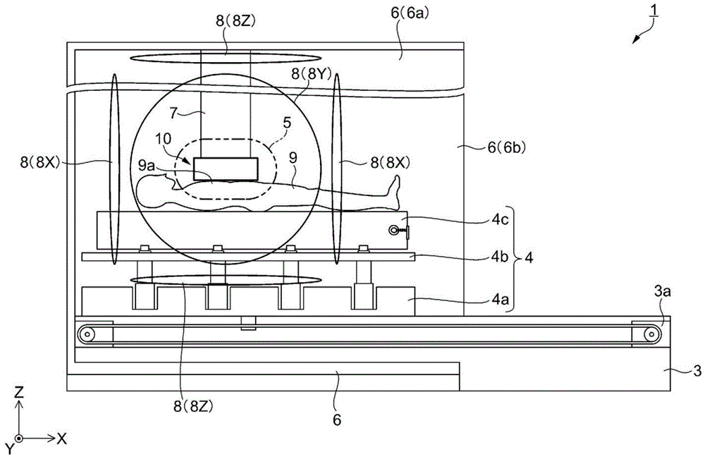
图1所示的磁场测量装置1是将测量对象物所产生的磁场作为矢量来测量的测量装置。其中,将测量与测量对象物所产生的磁场相关的一部分的信息(例如,其一个成分、大小、有无等)的装置称为磁测量装置。在本实施方式中,将测量对象物设为人体(被检体),将测量对象物所发出的磁场设为心磁(由心脏的电生理学的活动产生的磁场)、脑磁。在这里,以磁场测量装置1将心磁作为矢量来测量的测量装置的情况为例来进行说明。The magnetic
磁场测量装置1是使用光泵浦法来测量磁场的装置,是兼用泵浦光和探测光的所谓单光束方式。此外,并不局限于单光束方式的结构,也可以为将用于照射泵浦光的光源和用于照射探测光的光源分离的所谓双光束方式的结构。如图1所示,磁场测量装置1具备底座3、工作台4、磁屏蔽装置6、磁场产生器8、磁传感器10、以及运算控制部30(参照图7)。The magnetic
在图6所示的磁传感器10中,将从光源18射出的激光(也称为照射光)18a通过气室12的方向(照射方向)设为第三方向(在本实施方式中为Z方向)。将照射光的直线偏振光成分的振动方向设为第二方向(在本实施方式中为Y方向)。将与第二方向(Y方向)以及第三方向(Z方向)正交的方向设为第一方向(在本实施方式中X方向)。而且,将第一方向(X方向)、第二方向(Y方向)、第三方向(Z方向)作为正交坐标系的轴向,以下分别称呼为X轴方向、Y轴方向、Z轴方向。In the
在图1中,Z轴方向是铅垂方向,是磁场测量装置1的高度方向(图1的上下方向)。X轴方向以及Y轴方向是水平方向,是底座3、工作台4的上面延伸的方向。躺卧的状态的被检体9的身高方向(图1的左右方向)为沿着X轴方向的方向。因此,与被检体9的身高方向交叉的方向(从图1的里侧朝向跟前的方向)是Y轴方向。In FIG. 1 , the Z-axis direction is the vertical direction, and is the height direction of the magnetic field measuring device 1 (the vertical direction in FIG. 1 ). The X-axis direction and the Y-axis direction are horizontal directions, and are directions in which the upper surfaces of the
底座3被配置于磁屏蔽装置6(主体部6a)的内侧的底面上,沿着作为被检体9能够移动方向的X轴方向延伸到主体部6a的外侧。工作台4具有第一工作台4a、第二工作台4b、以及第三工作台4c。在底座3上设置有通过直动机构3a沿着X轴方向移动的第一工作台4a。在第一工作台4a上设置有通过未图示的升降装置沿着Z轴方向升降的第二工作台4b。在第二工作台4b上设置有通过未图示的直动机构在导轨上沿着Y轴方向移动的第三工作台4c。The
磁屏蔽装置6具备具有开口部6b的角筒状的主体部6a。主体部6a的内部为空洞,在Y轴方向以及Z轴方向构成的面(在Y-Z剖面上与X轴方向正交的平面)的剖面形状大体为四边形。在测量心磁时,被检体9以躺卧在工作台4上的状态被收纳在主体部6a的内部。主体部6a沿X轴方向延伸,其本身作为被动式磁屏蔽发挥功能。The
底座3从主体部6a的开口部6b向+X方向突出。磁屏蔽装置6的大小例如,X轴方向的长度约为200cm左右,开口部6b的一边是90cm左右。而且,躺卧于工作台4的被检体9能够与工作台4一起在底座3上沿着X轴方向移动,从开口部6b出入磁屏蔽装置6内。The
磁屏蔽装置6的主体部6a由相对磁导率例如是数千以上的强磁性体,或者高传导率的导体形成。强磁性体能够使用坡莫合金、铁素体、或者铁、铬或钴系的非晶体等。高传导率的导体能够使用例如由铝等通过涡流效应而具有磁场减少效果的材料。此外,还能够交替地层叠强磁性体和高传导率的导体来形成主体部6a。The
在主体部6a的内部设置有磁场产生器8。磁场产生器8由3轴亥姆霍兹线圈构成,能够对测量区域5,在X轴、Y轴以及Z轴的各轴向产生规定磁场。即,磁场产生器8至少包含产生X轴方向的磁场的第一磁场产生器8X、以及产生Y轴方向的磁场的第二磁场产生器8Y,优选还包含产生Z轴方向的磁场的第三磁场产生器8Z。A
在本实施方式中,磁场产生器8包含第一磁场产生器(沿着X轴方向对置的一对亥姆霍兹线圈)8X、第二磁场产生器(沿着Y轴方向对置的一对亥姆霍兹线圈)8Y、以及第三磁场产生器(沿着Z轴方向对置的一对亥姆霍兹线圈)8Z。磁屏蔽装置6的主体部6a内的成为磁场测量装置1测量心磁的对象的区域是测量区域5。作为被检体9的测量位置的胸部9a和磁传感器10被配置于测量区域5内。In this embodiment, the
如图2、图3以及图4所示,磁场产生器8所包含的亥姆霍兹线圈8X、亥姆霍兹线圈8Y以及亥姆霍兹线圈8Z的直径比测量区域5的直径大。即,测量区域5被内包在由第一磁场产生器8X、第二磁场产生器8Y以及第三磁场产生器8Z围起的区域。优选这些亥姆霍兹线圈8X、8Y、8Z的中心、测量区域5的中心、以及磁传感器10的中心大致一致。若像这样,在测量区域5中,能够高精度地测量作为三维矢量的磁场。As shown in FIGS. 2 , 3 and 4 , the diameters of the
另外,优选对置的一对亥姆霍兹线圈彼此之间的距离比其它亥姆霍兹线圈的直径大。例如,如图2、图3、以及图4所示,优选对置的一对亥姆霍兹线圈8X彼此之间的距离比亥姆霍兹线圈8Y以及亥姆霍兹线圈8Z的直径大。若像这样,能够通过一对亥姆霍兹线圈8Y(或者8Z),沿着Y轴(或者Z轴)产生平行且均匀的磁场。同样地,优选一对亥姆霍兹线圈8Y(或者8Z)彼此之间的距离也比其它亥姆霍兹线圈的直径大。In addition, it is preferable that the distance between a pair of opposing Helmholtz coils is larger than the diameter of the other Helmholtz coils. For example, as shown in FIGS. 2 , 3 , and 4 , it is preferable that the distance between the pair of opposing
在图2、图3以及图4中,假设一对亥姆霍兹线圈8X彼此之间的距离(例如在图2的情况下,左侧的亥姆霍兹线圈8X和右侧的亥姆霍兹线圈8X的沿着X轴的距离)比其它亥姆霍兹线圈8Y以及亥姆霍兹线圈8Z的直径小。在该情况下,亥姆霍兹线圈8X进入将一对亥姆霍兹线圈8Y(或者8Z)作为底面的圆柱状的区域的内侧。这样,通过一对亥姆霍兹线圈8Y(或者8Z)形成的磁场产生形变,难以在测量区域5附近沿着Y轴(或者Z轴)产生平行且均匀的磁场。In FIGS. 2, 3, and 4, it is assumed that a pair of
与此相对,在一对亥姆霍兹线圈8X彼此之间的距离比其它亥姆霍兹线圈8Y以及亥姆霍兹线圈8Z的直径大的情况下,亥姆霍兹线圈8X被配置于以一对亥姆霍兹线圈8Y(或者8Z)作为底面的圆柱状的区域的外侧。这样,通过亥姆霍兹线圈8X,抑制了通过一对亥姆霍兹线圈8Y(或者8Z)形成的磁场的形变,能够在测量区域5附近沿着中Y轴(或者Z轴)产生平行且均匀的磁场。On the other hand, when the distance between the pair of
像这样,优选在将一对亥姆霍兹线圈8X作为底面的圆柱状的区域的外侧,配置一对亥姆霍兹线圈8Y和一对亥姆霍兹线圈8Z。而且,优选在将一对亥姆霍兹线圈8Y作为底面的圆柱状的区域的外侧配置一对亥姆霍兹线圈8Z和一对亥姆霍兹线圈8X,在将一对亥姆霍兹线圈8Z作为底面的圆柱状的区域的外侧配置一对亥姆霍兹线圈8X和一对亥姆霍兹线圈8Y。As described above, it is preferable to arrange a pair of
此外,在本实施方式中将亥姆霍兹线圈的形状作为圆形来进行说明,但亥姆霍兹线圈的形状不限定于圆形,也可以是四边形等多边形。在亥姆霍兹线圈的形状是多边形的情况下,在将一对亥姆霍兹线圈作为底面的棱柱状的区域外,配置与该棱柱的高度方向正交的其它亥姆霍兹线圈。In addition, in the present embodiment, the shape of the Helmholtz coil is described as a circle, but the shape of the Helmholtz coil is not limited to a circle, and may be a polygon such as a quadrangle. When the shape of the Helmholtz coil is a polygon, other Helmholtz coils orthogonal to the height direction of the prism are arranged outside the prism-shaped region having a pair of Helmholtz coils as bottom surfaces.
磁传感器10被经由支承部件7固定于主体部6a的顶棚。磁传感器10对测量区域5在Z轴方向上的磁场的强度成分进行测量。磁传感器10使用光泵浦法来测量磁场。在测量被检体9的心磁时,使第一工作台4a以及第三工作台4c移动以便作为被检体9的测量位置的胸部9a处于与磁传感器10对置的位置,使第二工作台4b上升以便胸部9a接近磁传感器10。The
在使用了光泵浦式的磁传感器10的微弱磁场的测量中,优选消除存在于配置了气室12的测量区域5的、例如地磁、都市噪声等因环境从外部流入的磁场(原磁场)。因为若存在原磁场,则受到其影响,导致针对测量对象物(被检体9)所产生的磁场的灵敏度的降低、测量精度的降低。在本实施方式中,通过磁屏蔽装置6抑制从外部向测量区域5的磁场的流入。而且,能够通过配置于主体部6a的内部的磁场产生器8将测量区域5附近保持在接近零磁场的低磁场。In the measurement of the weak magnetic field using the optically pumped
如图5所示,磁传感器10具有光源18、气室12、以及光检测器14、15。光源18输出与铯的吸收线对应的波长的激光18a。激光18a的波长并没有被特别限定,在本实施方式中,例如,设定为与D1线相当的894nm的波长。光源18是可调谐激光器,从光源18输出的激光18a是具有一定的光量的连续光。As shown in FIG. 5 , the
在本实施方式中,光源18被设置于运算控制部30。从光源18发出的激光18a通过光纤19被供给至磁传感器10的主体。磁传感器10的主体和光纤19经由光连接器20连接。经由光连接器20供给的激光18a向-Y方向行进而入射至偏光板21。通过偏光板21的激光18a为直线偏振光。而且,激光18a依次入射至第一半透半反镜22、第二半透半反镜23、第三半透半反镜24、第一反射镜25。In the present embodiment, the
第一半透半反镜22、第二半透半反镜23以及第三半透半反镜24对激光18a的一部分进行反射使其向+X方向行进,并使一部分激光18a通过使其向-Y方向行进。第一反射镜25将入射的激光18a全部向+X方向反射。通过第一半透半反镜22、第二半透半反镜23、第三半透半反镜24、第一反射镜25,将激光18a分割为4个光路。以各光路的激光18a的光强度成为相同的光强度的方式,设定各反射镜的反射率。The first half mirror 22, the
接下来,如图6所示,激光18a依次照射入射至第四半透半反镜26、第五半透半反镜27、第六半透半反镜28、第二反射镜29。第四半透半反镜26、第五半透半反镜27以及第六半透半反镜28对激光18a的一部分进行反射使其向+Z方向行进,使一部分激光18a通过使其向+X方向行进。第二反射镜29将入射的激光18a全部向+Z方向反射。Next, as shown in FIG. 6 , the
利用第四半透半反镜26、第五半透半反镜27、第六半透半反镜28、第二反射镜29,将一个光路的激光18a分割为4个光路。以各光路的激光18a的光强度成为相同的光强度的方式,设定各反射镜的反射率。因此,激光18a分离为16个光路。而且,以各光路的激光18a的光强度成为相同的强度的方式,设定各反射镜的反射率。The
在第四半透半反镜26、第五半透半反镜27、第六半透半反镜28、第二反射镜29的+Z方向侧,在激光18a的各光路设置有4行4列16个气室12。而且,被第四半透半反镜26、第五半透半反镜27、第六半透半反镜28、第二反射镜29反射的激光18a通过气室12。On the +Z direction side of the
气室12是在内部具有空隙的箱,在该空隙装入有作为根据测量区域5(参照图1)的磁场而使光的光学特性变化的介质的碱金属的气体。碱金属。并没有被特别限定,能够使用钾、铷或者铯。在本实施方式中,例如碱金属使用铯。The
在各气室12的+Z方向侧设置有偏振光分离器13。偏振光分离器13是将入射的激光18a分离为相互正交的两个偏振光成分的激光18a的元件。偏振光分离器13例如能够使用沃拉斯顿棱镜或者偏振分束器。A
在偏振光分离器13的+Z方向侧设置有光检测器14,在偏振光分离器13的+X方向侧设置有光检测器15。通过偏振光分离器13的激光18a入射至光检测器14,被偏振光分离器13反射的激光18a入射至光检测器15。光检测器14以及光检测器15将与入射的激光18a的受光光量对应的信号输出至运算控制部30。The
由于若光检测器14、15产生磁场则有给测定带来影响的可能性,所以优选光检测器14、15由非磁性的材料构成。磁传感器10具有被设置于X轴方向的两面以及Y轴方向的两面的加热器16。加热器16优选不产生磁场的构造,例如,能够使用在流路中使蒸气、热风通过来加热的方式的加热器。也可以代替加热器,通过高频电压来对气室12进行介电加热。The
磁传感器10被配置于被检体9(参照图1)的+Z方向侧。由磁传感器10在测量区域5检测的磁场矢量B(包含测定对象物所产生的对象磁场矢量)从-Z方向侧进入磁传感器10。磁场矢量B在通过第四半透半反镜26~第二反射镜29,并通过气室12后,通过偏振光分离器13从磁传感器10出来。The
磁传感器10是被称为光泵浦式磁传感器、光泵浦原子磁传感器的传感器。气室12内的铯被加热而成为气体状态。而且,通过将成为直线偏振光的激光18a照射至铯气体,铯原子被激发且使磁力矩的方向一致。在该状态下磁场矢量B通过气室12时,铯原子的磁力矩通过磁场矢量B的磁场进动。将该进动称为拉莫尔进动。The
拉莫尔进动的大小具有与磁场矢量B的强度正的相关。拉莫尔进动使激光18a的偏转面旋转。拉莫尔进动的大小和激光18a的偏转面的旋转角的变化量具有正的相关。因此,磁场矢量B的强度和激光18a的偏转面的旋转角的变化量具有正的相关。磁传感器10的灵敏度在磁场矢量B的Z轴方向升高,在与Z轴方向正交的方向降低。The magnitude of the Larmor precession has a positive correlation with the strength of the magnetic field vector B. The Larmor precession rotates the deflection plane of the
偏振光分离器13将透过气室12的激光18a分离为相互正交的轴向(图11所示的α轴以及β轴)的2个成分的直线偏振光。分离出的一方的直线偏振光被导入光检测器14,另一方的直线偏振光被导入光检测器15。而且,光检测器14以及光检测器15接收正交的2个成分各自的直线偏振光,产生与受光光量对应的信号并输出至运算控制部30。能够通过检测各个直线偏振光的强度,来检测激光18a的偏转面的旋转角。而且,能够根据激光18a的偏转面的旋转角的变化,来检测磁场矢量B的强度。The
将由气室12、偏振光分离器13、光检测器14以及光检测器15构成的元件称为传感器元件11。在本实施方式中,在磁传感器10配置有4行4列16个传感器元件11。磁传感器10的传感器元件11的个数以及配置并没有被特别限定。传感器元件11也可以3行以下也可以5行以上。同样,传感器元件11也可以3列以下也可以5列以上。传感器元件11的个数越多越能够提高空间分辨率。The element composed of the
如图7所示,运算控制部30具有操作部31、显示部32、通信部33、处理部40以及存储部50。操作部31是按钮开关、触摸面板、键盘、各种传感器等输入装置,将与进行的操作对应的操作信号输出至处理部40。通过该操作部31,进行磁场测量的开始指示等各种指示输入。As shown in FIG. 7 , the
显示部32是LCD(Liquid Crystal Display:液晶显示器)等显示装置,进行基于来自处理部40的显示信号的各种显示。在该显示部32显示测量结果等。通信部33是无线通信器、调制解调器、有线用的通信电缆的插座、控制电路等通信装置,与被给予的通信线路连接来实现与外部的通信。The
处理部40例如通过CPU(Central Processing Unit:中央处理单元)、GPU(Graphics Processing Unit:图形处理单元)等微处理器、ASIC(针对特定用途的集成电路:Application Specific Integrated Circuit)、IC(Integrated Circuit:集成电路)存储器等电子部件来实现。处理部40基于规定的程序、数据、来自操作部31的操作信号、来自磁传感器10的测量信号等来执行各种运算处理,并控制运算控制部30的动作。The
处理部40具有照射控制部41、磁场产生控制部42、原磁场计算部43、偏置磁场决定部44以及对象磁场计算部45。处理部40执行根据存储部50所存储的磁场测量程序51的磁测量处理(参照图13所示的流程图)。The
在本实施方式所涉及的磁测量处理中,例如在进行人体的心脏、脑这样测定对象物所产生的磁场的测定前,作为初始设定,计算未放置测定对象物的状态的测量区域5的原磁场Cx。而且,在使磁场产生器8产生了像消除原磁场Cx那样的偏置磁场的状态下,进行测定对象物所产生的磁场的测定。即,测定对象物(被检体9)所产生的磁场的测量在减少了流入测量区域5的外部磁场(原磁场)的状态下实施。In the magnetic measurement process according to the present embodiment, before the measurement of the magnetic field generated by the measurement object such as the human heart and the brain, for example, as an initial setting, the measurement area 5 in the state where the measurement object is not placed is calculated. The original magnetic field C x . Then, the measurement of the magnetic field generated by the object to be measured is performed in a state where the
照射控制部41控制磁传感器10的光源18的照射光的照射。具体而言,照射控制部41除了光源18的照射光的照射的开始、结束以外,还控制照射光的光强度、照射光所包含的直线偏振面的方向等。The
磁场产生控制部42对磁场产生器8(8X、8Y、8Z),以在X、Y、Z轴方向分别产生规定的磁场的方式进行控制。具体而言,磁场产生控制部42在初始设定时使磁场产生器8(8X、8Y、8Z)产生规定的人工磁场A(Ax、Ay、Az)。详细内容后述,但人工磁场A是其第一方向(X方向)成分以及第二方向(Y方向)成分是振幅以及周期相同且相位不同的交变磁场f(ωt),其第三方向(Z方向)成分是零(Az=0)的磁场矢量。人工磁场A(Ax、Ay、Az)作为人工磁场数据52被存储至存储部50。The magnetic field
另外,磁场产生控制部42在测定时使磁场产生器8(8X、8Y、8Z)产生由偏置磁场决定部44决定出的偏置磁场Bb(Bbx、Bby、Bbz)与人工磁场A(Ax、Ay、Az)的合成磁场(Bb+A)。In addition, the magnetic field
此外,也可以使磁场产生器8X依次产生X侧第一能级的恒定磁场、X侧第二能级的恒定磁场以及X侧第三能级的恒定磁场作为人工磁场A的X轴方向成分Ax。同样,也可以使磁场产生器8Y依次产生Y侧第一能级的恒定磁场、Y侧第二能级的恒定磁场以及Y侧第三能级的恒定磁场作为人工磁场A的Y轴方向成分Ay。另外,也可以使磁场产生器8X依次产生X侧第一能级的恒定磁场、以及X侧第二能级的恒定磁场作为人工磁场A的X轴方向成分Ax,使磁场产生器8Y依次产生Y侧第一能级的恒定磁场以及Y侧第二能级的恒定磁场作为人工磁场A的Y轴方向成分Ay。In addition, the
原磁场计算部43在磁场产生器8(8X、8Y、8Z)产生人工磁场矢量A(Ax、Ay、Az)的状态下,基于从磁传感器10输出的信号,来计算原磁场矢量C(Cx、Cy、Cz)。具体而言,将基于从磁传感器10输出的信号得到的磁传感器测量值(平方差W-)作为自旋极化度Mx,获取某一时刻t的人工磁场矢量A的X轴方向成分Ax的值Ax(t)、以及Y轴方向成分Ay的值Ay(t)与自旋极化度Mx(t)的组合,且是自旋极化度Mx不同的3个以上的组合。The original magnetic
而且,定义由将获取到的组合分别代入后述的公式17而得到的3个以上的式子构成的连立方程式,并执行求解该连立方程式的规定的算术运算处理,从而计算原磁场矢量C(Cx、Cy、Cz)。计算出的原磁场C(Cx、Cy、Cz)作为原磁场数据53被存储至存储部50。Then, a continuous equation composed of three or more expressions obtained by substituting the acquired combinations into Equation 17 to be described later is defined, and a predetermined arithmetic operation process for solving the continuous equation is performed to calculate the original magnetic field vector C(C x , Cy , C z ). The calculated original magnetic field C (C x , C y , C z ) is stored in the
偏置磁场决定部44决定消除由原磁场计算部43计算出的原磁场矢量C(Cx、Cy、Cz)的偏置磁场Bb(Bbx、Bby、Bbz)。决定出的偏置磁场Bb(Bbx、Bby、Bbz)作为偏置磁场数据54存储至存储部50。The bias magnetic
对象磁场计算部45在配置有测定对象物,磁场产生器8产生偏置磁场Bb的状态下,基于从磁传感器10输出的信号,计算该测定对象物所产生的对象磁场矢量B(Bx、By、Bz)。具体而言,将基于从磁传感器10输出的信号得到的测量值(平方差W-)作为自旋极化度Mx,获取某一时刻t的人工磁场矢量A的X轴方向成分Ax的值Ax(t)、以及Y轴方向成分Ay的值Ay(t)与自旋极化度Mx(t)的组合,且是自旋极化度Mx不同的3个以上的组合。The target magnetic
而且,定义由将获取到的组合分别代入公式17而得到的3个以上的式子构成的连立方程式,并执行求解该连立方程式的规定的算术运算处理,从而作为测定对象物所产生的对象磁场B(Bx、By、Bz)来计算原磁场矢量C(Cx、Cy、Cz)。计算出的对象磁场矢量B(Bx、By、Bz)作为测定磁场数据55存储至存储部50。另外,基于从磁传感器10输出的信号得到的磁传感器测量值(平方差W-)作为磁传感器测量数据56被存储至存储部50。Then, a continuous equation composed of three or more equations obtained by substituting the acquired combinations into Equation 17 is defined, and a predetermined arithmetic operation process for solving the continuous equation is performed, thereby generating a measurement target object. The original magnetic field vector C (C x , Cy , C z ) is calculated for the object magnetic field B (B x , By , B z ). The calculated target magnetic field vector B (B x , By , B z ) is stored in the
存储部50由ROM(Read Only Memory:只读存储器)、RAM(Random Access Memory:随机存取存储器)、硬盘等存储装置构成。存储部50存储用于处理部40统一地控制运算控制部30的程序、数据等,并且作为处理部40的作业区域来使用,暂时储存处理部40所执行的运算结果、来自操作部31的操作数据等。在本实施方式中,存储部50存储磁场测量程序51、人工磁场数据52、原磁场数据53、偏置磁场数据54、测定磁场数据55以及磁传感器测量数据56。The
原理principle
对磁场测量装置1中的磁场的测量原理进行说明。图8是对没有磁场的情况下的对准进行说明的图。图9是对由磁场引起的对准的变化进行说明的图。图10以及图11是对由透过气室引起的直线偏振光的偏振面的变化进行说明的图。图12是表示对准方位角θ与探测光的检测结果的关系的图。The measurement principle of the magnetic field in the magnetic
应予说明,在以下的说明中,为了容易理解原理进行时间序列性地描述,但实际上(A)光泵浦以及(C)探测能够在本实施方式的单光束方式下同时产生。It should be noted that, in the following description, in order to facilitate understanding of the principle, the description is made in time series, but actually (A) optical pumping and (C) detection can be simultaneously generated in the single beam method of the present embodiment.
(A)光泵浦(A) Optical pumping
被装入气室12的碱金属原子的气体为照射被调整为与从D1线的超微小构造量子数F向F′(=F-1)的状态的迁移相当的波长的泵浦光(在本实施方式中,为通过气室12的光),从而自旋大致朝向反平行(相反方向)的(自旋极化)原子大致相同数目地混合存在的集团。将该状态称为对准。此外,一个原子的自旋极化随着时间的经过缓和,但由于泵浦光是CW(continuous wave:连续波)光,所以自旋极化的形成和缓和同时并行且连续地重复,其结果为,若视为原子的集团整体则形成稳定的自旋极化。The gas of the alkali metal atoms charged into the
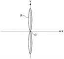
在测量区域5是零磁场的情况下,对准以原子的磁力矩的概率分布来表示。如本实施方式那样在泵浦光是直线偏振光的情况下,如图8所示,其形状在X-Y平面中,为连结了沿着泵浦光的直线偏振光的电场的振动方向(在本实施方式中,是Y轴方向)延伸的两个椭圆而成的区域R的形状。In the case of a zero magnetic field in the measurement region 5, the alignment is represented by the probability distribution of the magnetic moments of the atoms. When the pump light is linearly polarized light as in the present embodiment, as shown in FIG. 8 , the shape is in the X-Y plane, and is the vibration direction of the electric field connecting the linearly polarized light along the pump light (in this case In the embodiment, it is the shape of the region R formed by two ellipses extending in the Y-axis direction).
(B)磁场的作用(B) Effect of magnetic field
若在测量区域5存在一些磁场,则碱金属原子将该磁场矢量(气室12所受到的磁场)的方向作为旋转轴开始进动。而且,如图9所示,通过施加泵浦光的光泵浦作用、和气体原子与气室12的内壁碰撞等引起的缓和作用,对准的方向(椭圆的长径沿着的方向)变化为以原点O为中心旋转。If there is some magnetic field in the measurement region 5, the alkali metal atoms start to precess in the direction of the magnetic field vector (the magnetic field received by the gas cell 12) as the axis of rotation. Furthermore, as shown in FIG. 9 , the alignment direction (the direction along which the major axis of the ellipse follows) changes due to the optical pumping action of the pump light and the relaxation action due to the collision of the gas atoms with the inner wall of the
对准的方向以相对于Y轴旋转了与磁场的强度对应的角度(θ)的配置成为稳定状态。在这里,将对准方向设为θp,将其正交方向设为θs。另外,将对准方向θp与作为泵浦光的电场的振动方向的Y轴方向所成的角θ设为对准方位角θ。该对准方位角θ主要根据Z轴方向的磁场强度而增加。The alignment direction is in a stable state with an arrangement rotated by an angle (θ) corresponding to the strength of the magnetic field with respect to the Y axis. Here, let the alignment direction be θp, and let the orthogonal direction be θs. In addition, let the angle θ formed by the alignment direction θp and the Y-axis direction, which is the vibration direction of the electric field of the pump light, be the alignment azimuth angle θ. The alignment azimuth angle θ increases mainly in accordance with the magnetic field strength in the Z-axis direction.
(C)探测(C) Detection
考虑具有在Y轴方向以电场矢量E0振动的直线偏振光成分的探测光(在本实施方式中,为通过气室12的光)通过该状态的原子集团的状况。即,如图10所示,使探测光的电场的振动方向沿着Y轴方向的直线偏振光朝向+Z方向通过气室12。在图10中,原点O相当于原子集团(被装入气室12的气体原子)的位置,该原子集团被光泵浦,从而产生分布于沿着Y轴方向的区域的对准。在Z轴方向上,-Z方向侧表示透过原子集团之前的直线偏振光,+Z方向表示透过了原子集团的直线偏振光(透过光)。Consider a situation where probe light having a linearly polarized light component vibrating with an electric field vector E 0 in the Y-axis direction (in this embodiment, light passing through the gas cell 12 ) passes through the atomic group in this state. That is, as shown in FIG. 10 , the linearly polarized light whose vibration direction of the electric field of the probe light is along the Y-axis direction is caused to pass through the
若直线偏振光透过原子集团,则由于线性二色性直线偏振光的偏振面旋转,该电场矢量变化为E1。所谓线性二色性是在沿着对准的方向θp(参照图9)、和与对准垂直的方向θs(参照图9)上直线偏振光的透过率不同的性质。具体而言,由于与沿着对准的方向θp相比,与对准垂直的方向θs的成分被较多地吸收,所以探测光的偏振面以接近沿着对准的方向θp的方式旋转。When the linearly polarized light passes through the atomic group, the electric field vector changes to E 1 due to the rotation of the polarization plane of the linearly dichroic linearly polarized light. The linear dichroism is a property that the transmittance of linearly polarized light differs in the direction θp along the alignment (see FIG. 9 ) and the direction θs perpendicular to the alignment (see FIG. 9 ). Specifically, since the component in the direction θs perpendicular to the alignment is absorbed more than the direction θp along the alignment, the polarization plane of the probe light rotates so as to be closer to the direction θp along the alignment.
图11是将直线偏振光透过原子集团的前后的偏振面的旋转的情况示于与作为探测光的照射方向的Z轴方向垂直的X-Y平面的图。在本实施方式中,入射至气室12的探测光是电场的振动方向为Y轴方向的电场矢量E0的直线偏振光。通过对准,探测光中的方向θp的成分以透过率tp透过,方向θs的成分以透过率ts透过。由于线性二色性tp>ts,所以透过气室12的探测光的偏振面以接近方向θp的方式旋转。这样通过气室12的光成为具有电场矢量E1的光。11 is a diagram showing the rotation of the plane of polarization before and after the transmission of linearly polarized light through the atomic group on the XY plane perpendicular to the Z-axis direction, which is the irradiation direction of probe light. In the present embodiment, the probe light incident on the
具体地说,将电场矢量E0的沿着对准的成分记作E0P,将电场矢量E0的沿着与对准和直线偏振光的行进方向垂直的方向的成分记作E0s。另外,将电场矢量E1的沿着对准的成分记作E1P,将电场矢量E1的沿着与对准和直线偏振光的行进方向垂直的方向的成分记作E1s。在该情况下,成为E1P=tpE0P、和E1s=tsE0s的关系。Specifically, the component of the electric field vector E 0 along the alignment is denoted as E 0P , and the component of the electric field vector E 0 along the direction perpendicular to the traveling direction of the alignment and linearly polarized light is denoted as E 0s . In addition, the component of the electric field vector E 1 along the alignment is denoted as E 1P , and the component of the electric field vector E 1 along the direction perpendicular to the traveling direction of the alignment and linearly polarized light is denoted as E 1s . In this case, the relationship of E 1P =t p E 0P and E 1s =t s E 0s is established.
若将沿着对准的方向与探测光的电场的振动方向所成的角(以下,称为“对准方位角”。)设为θ,则根据上述关系,电场矢量E1的方向θp以及方向θs的各成分通过以下的公式4来计算。If the angle formed by the direction along the alignment and the vibration direction of the electric field of the probe light (hereinafter, referred to as "alignment azimuth") is θ, then from the above relationship, the direction θp of the electric field vector E1 and Each component of the direction θs is calculated by the following formula 4.
[式4][Formula 4]

如上所述,透过气室12的探测光通过偏振光分离器13而被分离为与作为探测光的照射方向的Y轴方向成+45度的α轴、以及与Y轴方向成-45度的β轴这两个偏振光成分。透过气室12的电场矢量E1的直线偏振光的α轴方向成分Eα和β轴方向成分Eβ通过公式5来计算。As described above, the probe light transmitted through the
[式5][Formula 5]

光检测器14、15测量α轴和β轴两个偏振光成分各自的光强度,并将与受光光量对应的信号输出至运算控制部30。运算控制部30对来自光检测器14、15的信号进行处理,根据以下的公式6、公式7计算α轴以及β轴的各轴向的成分的平方和W+和平方差W-。Eα表示α轴向的成分的光强度,Eβ表示β轴向的成分的光强度。The
[式6][Formula 6]
W+=Eα 2+Eβ 2...(6)W + =E α 2 +E β 2 ...(6)
[式7][Formula 7]
W-=Eα 2-Eβ 2...(7)W - =E α 2 -E β 2 ...(7)
图12示有相对于对准方位角θ的、电场矢量E1的直线偏振光的α轴以及β轴向成分Eα、Eβ,以及各个的平方值Eα 2、Eβ 2,α轴以及β轴的各轴向的成分的平方和W+和平方差W-。此外,所谓对准方位角θ=0是测量区域5为零磁场的状态(参照图8)。其中,方向θp的成分的透过率tp=1,方向θs的成分的透过率ts=0.8。12 shows the α-axis and β-axis components E α , E β of the linearly polarized light of the electric field vector E 1 with respect to the alignment azimuth angle θ, and the respective square values E α 2 , E β 2 , the α-axis And the square sum W + and the square difference W − of the components of each axis of the β axis. In addition, the so-called alignment azimuth angle θ=0 refers to a state in which the measurement region 5 has zero magnetic field (see FIG. 8 ). Here, the transmittance of the component in the direction θp is t p =1, and the transmittance of the component in the direction θs is ts=0.8.
在图12中,若着眼于平方差W-的值,则平方差W-相对于对准方位角θ以180度为周期振动。而且,由于平方差W-在对准方位角θ从-45度到+45度的范围中,相对于对准方位角θ大致线性变化,所以得到较高的灵敏度。另外,由于该线性变化的中心是0度,其线性变化的范围比其他(平方和W+等)宽,所以对测量测量区域5所产生的磁场而言优选。由于心磁、脑磁等生物体磁场微弱,对准方位角θ较小,所以若使用平方差W-则能够高灵敏度地观测偏振面的旋转角度。In FIG. 12 , if attention is paid to the value of the squared difference W − , the squared difference W − vibrates at a period of 180 degrees with respect to the alignment azimuth angle θ. Furthermore, since the squared difference W − varies substantially linearly with respect to the alignment azimuth angle θ in the range of the alignment azimuth angle θ from -45 degrees to +45 degrees, high sensitivity is obtained. In addition, since the center of the linear change is 0 degrees, the range of the linear change is wider than others (square sum W + etc.), so it is preferable to measure the magnetic field generated by the measurement area 5 . Since the biological magnetic field such as cardiac magnetism and brain magnetism is weak and the alignment azimuth θ is small, the rotation angle of the polarization plane can be observed with high sensitivity by using the squared difference W − .
其中,如上所述,若在测量区域5存在与测量对象的磁场不同的不必要的磁场则受到其该影响灵敏度降低,导致测量精度的降低。通常在测量心磁、脑磁等测量对象的磁场时,在通过磁屏蔽装置6抑制了向测量区域5的来自外部的磁场的侵入的环境下(外部磁场较小的状态)下进行,但通过磁屏蔽装置6将外部磁场充分地减少到对测定没有影响的程度很困难。换言之,不能够通过磁屏蔽装置6将外部磁场的侵入完全遮挡的情况较多。能够完全遮挡磁的磁屏蔽装置不仅大型,费用昂贵,并且设置成本、运用成本也较高。However, as described above, if an unnecessary magnetic field different from the magnetic field of the object to be measured exists in the measurement region 5, the sensitivity decreases due to the influence, resulting in a decrease in measurement accuracy. Usually, when measuring the magnetic field of a measurement object such as cardiomagnetic and encephalomagnetic fields, the
因此,在本实施方式中,在使用了磁屏蔽装置6的基础上,对漏入磁屏蔽装置6内的外部磁场(称为原磁场C)进行测量,并在通过磁场产生器8减少了该外部磁场的状态下对测量对象的磁场进行测量。其中,在原本外部磁场较低的情况下、外部磁场稳定的情况下,即使不使用磁屏蔽装置6也能够构成本实施方式。Therefore, in this embodiment, in addition to using the
根据图12,在对准方位角θ从-45度到+45度的范围中,平方差W-与自旋极化度(Mx、My、Mz)的X轴方向成分Mx(以下,记作自旋极化度Mx)大致成比例。该自旋极化度Mx相当于作为合成了原子的磁力矩的磁化矢量的X轴方向成分的磁化值。因此,以下,将平方差W-作为自旋极化度Mx来处理。在本实施方式中,着眼于该自旋极化度Mx,导出表示自旋极化度Mx的值根据对气室12施加的磁场矢量B的各成分Bx、By、Bz如何变化的关系式。According to FIG. 12 , in the range of the alignment azimuth θ from -45 degrees to +45 degrees, the square difference W − and the X -axis direction component M x ( Hereinafter, it is referred to as the spin polarization degree M x ) which is approximately proportional. The spin polarization degree M x corresponds to the magnetization value of the X-axis direction component of the magnetization vector in which the magnetic moment of the atom is synthesized. Therefore, in the following, the squared difference W − is treated as the degree of spin polarization M x . In the present embodiment, focusing on the spin polarization degree M x , a value representing the spin polarization degree M x is derived according to how the components B x , By , and B z of the magnetic field vector B applied to the
通过光泵浦产生的对准的自旋极化度(Mx、My、Mz)的时间发展用以下的公式8~公式10所示的布洛赫方程式(Bloch equations)来近似。γF表示由气室12内的介质气体(碱金属原子气体)的种类决定的磁旋转比。另外,Γ0表示自旋极化度(Mx、My、Mz)的缓和速度,Γp表示光泵浦速度。Mp是碱金属原子集团的自旋全部汇聚到一个方向时的最大磁化。The time development of the aligned spin polarizability (M x , My , M z ) by optical pumping is approximated by the Bloch equations shown in
[式8][Formula 8]

[式9][Formula 9]

[式10][Formula 10]

由于泵浦光以及探测光被稳定地以恒定的功率照射至气室12,所以自旋极化度(Mx、My、Mz)的稳态解能够在将上述公式8~公式10的左边分别置为零来解出。解通过公式11~公式13得到。Since the pump light and the probe light are stably irradiated to the
[式11][Formula 11]

[式12][Formula 12]

[式13][Formula 13]

在公式11~公式13中,a、c是常量,通过以下的公式14给出。In
[式14][Formula 14]

(D)磁场的测量(D) Measurement of the magnetic field
那么,考虑通过磁场产生器8(8X、8Y、8Z)对气室12在X、Y、Z轴方向分别产生/施加人工磁场A(Ax、Ay、Az)的情况。在该情况下,磁传感器10所检测的磁场矢量B(Bx、By、Bz)如公式15所示,为磁场产生器8所产生的人工磁场矢量A(Ax、Ay、Az)与原磁场矢量C(Cx、Cy、Cz)的矢量和。所谓的原磁场C是在人工磁场A为零时存在于测量区域5的磁场。Then, consider the case where artificial magnetic fields A (A x , A y , A z ) are generated/applied to the
[式15][Formula 15]

在这里,将人工磁场矢量A的Z轴方向成分Az设为零(Az=0)。另外,将人工磁场矢量A的X轴方向成分Ax设为具有振幅A10的函数A10f(t),将Y轴方向成分Ay设为具有振幅A20的函数A20g(t)。因此,磁传感器10在测量区域5检测的磁场矢量B(Bx、By、Bz)为以下的公式16。此外,振幅A10和振幅A20是具有磁场的维度的系数,函数f(t)和函数g(t)是非维度(无维)函数。Here, the Z-axis direction component A z of the artificial magnetic field vector A is set to zero (A z =0). In addition, let the X-axis direction component A x of the artificial magnetic field vector A be a function A 10 f(t) having an amplitude A 10 , and the Y-axis direction component A y shall be a function A 20 g(t) having an amplitude A 20 . Therefore, the magnetic field vector B (B x , By , B z ) detected by the
[式16][Formula 16]

若将该公式16代入公式11的自旋极化度Mx代入,则得到公式17。When this
[式17][Formula 17]

此外,若A10=A20=A0则控制和计算很容易,上述公式成为以下的公式18。In addition, if A 10 =A 20 =A 0 , control and calculation are easy, and the above formula becomes the following
[式18][Formula 18]

若将该公式18代入公式11的自旋极化度Mx,则得到公式19。When this
[式19][Formula 19]

而且,使用公式19,以如下的方式计算作为未知数的原磁场矢量C的各成分(Cx、Cy、Cz)的3个值。即,进行使用了磁场测量装置1的测量,获取某一时刻t的、由磁场产生器8产生的人工磁场A的X轴方向成分Ax(t)、以及Y轴方向成分Ay(t)与自旋极化度Mx(t)(即,磁传感器10的输出值W-)的组合,且是自旋极化度Mx(t)不同的3以上的组合。Then, using
而且,按每一个组合来生成由将人工磁场Ax(t)、Ay(t)、以及自旋极化度Mx(t)代入公式19所得到的3个式子构成的连立方程式。通过求解该连立方程式,能够计算作为未知数的原磁场矢量C的各成分(Cx、Cy、Cz)。Then, a continuous equation composed of three equations obtained by substituting artificial magnetic fields A x (t), A y (t), and spin polarization M x (t) into
此外,在公式19中,常量a、c也可以为未知数。即,公式19中包含原磁场矢量C的各成分(Cx、Cy、Cz)、以及常量a、c这5个未知数。在该情况下,进行使用了磁场测量装置1的测量,获取某一时刻t的人工磁场Ax(t)、Ay(t)与自旋极化度Mx(t)的组合,且是自旋极化度Mx(t)不同的5个组合。而且,按每一个组合来生成由将各值代入公式19所得的5个式子构成的连立方程式。通过求解该连立方程式,能够计算作为未知数的原磁场矢量C的各成分(Cx、Cy、Cz)、以及常量a、c。In addition, in
而且,获取人工磁场Ax(t)、Ay(t)与自旋极化度Mx(t)的组合,且是自旋极化度Mx(t)不同的6个以上的组合,也可以实施公式19的拟合。具体而言,以使用公式19计算出的自旋极化度Mx、和作为磁传感器10的测量值的Mx的偏差成为最小的方式,来计算作为未知数的原磁场矢量C的各成分(Cx、Cy、Cz)、以及常量a、c。Then, combinations of artificial magnetic fields A x (t), A y (t) and spin polarization degrees M x (t) are obtained, and six or more combinations of different spin polarization degrees M x (t) are obtained, The fitting of
另外,若将作为人工磁场Ax、Ay的时间函数f(t)、g(t)的振幅A0与原磁场C的X轴方向成分Cx、以及Y轴方向成分Cy相比设为充分小(大体是1/10以下。A0<(Cx/10)、A0<(Cy/10)),公式19被简化为公式20,测量变得更加容易。In addition, if the amplitudes A 0 which are the time functions f(t) and g(t) of the artificial magnetic fields A x and A y are compared with the X-axis direction component C x and the Y-axis direction component C y of the original magnetic field C, it is assumed that In order to be sufficiently small (generally 1/10 or less. A 0 <(C x /10), A 0 <(C y /10)),
[式20][Formula 20]

这样,能够使用公式19、公式20,根据由磁场产生器8产生的人工磁场A(Ax、Ay、Az)以及此时的自旋极化度Mx(即,平方差W-),计算原磁场矢量C(Cx、Cy、Cz)。In this way, the artificial magnetic field A (A x , A y , A z ) generated by the
(E)人工磁场A(E) Artificial magnetic field A
以如下的方式确定人工磁场A(Ax、Ay、Az)。即,人工磁场A的X轴方向成分Ax的时间函数f(t)取作为分别不同的n个能级的固定值fi(i=1、…、n),人工磁场A的Y轴方向成分Ay的时间函数g(t)取作为分别不同的m个能级的固定值gj(j=1、…、m)。伴随于此,以存在与时间函数g(t)、f(t)各个固定值fi、gj的全部的组合对应的合计n×m个测量期间τk(k=i、…、n×m)的方式,确定时间函数f(t)、g(t)。The artificial magnetic field A (A x , A y , A z ) is determined in the following manner. That is, the time function f(t) of the component A x in the X-axis direction of the artificial magnetic field A is taken as a fixed value f i (i=1, . The time function g(t) of the component A y is taken as a fixed value g j (j=1, . . . , m) for the m energy levels which are respectively different. Along with this, there are a total of n×m measurement periods τk ( k = i , . ) to determine the time functions f(t) and g(t).
在本实施方式中,如上述那样,为了计算原磁场矢量C的各成分(Cx、Cy、Cz),需要获取某一时刻t的人工磁场Ax(t)、Ay(t)与自旋极化度Mx(t)的组合,且是自旋极化度Mx(t)不同的3个以上的组合。即,需要以存在3个以上的测量期间τk(k≥3)的方式,确定时间函数f(t)、g(t)分别所取的固定值fi、gj。In this embodiment, as described above, in order to calculate each component (C x , C y , C z ) of the original magnetic field vector C, it is necessary to acquire the artificial magnetic fields A x (t) and A y (t) at a certain time t The combination with the spin polarization degree M x (t) is a combination of three or more different spin polarization degrees M x (t). That is, it is necessary to determine the fixed values f i and g j respectively taken by the time functions f(t) and g(t) so that there are three or more measurement periods τk (k≧3).
而且,与人工磁场Ax、Ay各自的时间函数f(t)、g(t)的固定值fi、gi的组合对应的测量期间τk的自旋极化度Mx分别从公式19、公式20变为以下的公式21、公式22。此外,这里将f(t)=fi、g(t)=gj时的自旋极化度Mx(t)记作Mxij。In addition, the spin polarization degree M x of the measurement period τk corresponding to the combination of the fixed values f i and gi of the time functions f(t) and g(t) of the artificial magnetic fields A x and A y is obtained from the
[式21][Formula 21]

[式22][Formula 22]

由于未知数是Cx、Cy、Cz这三个,所以测量三个以上的Mxij。因此,在使X侧和Y侧这两者变化时,n是2以上的整数,m是2以上的整数,合计测量四个以上的Mxij。在仅使X侧变化时,n是3以上的整数,测量三个以上的Mxij。在仅使Y侧变化时,m是3以上的整数,测量三个以上的Mxij。Since the unknowns are three of Cx , Cy , and Cz , three or more Mxijs are measured. Therefore, when changing both the X side and the Y side, n is an integer of 2 or more, m is an integer of 2 or more, and a total of four or more M xij are measured. When changing only the X side, n is an integer of 3 or more, and three or more M xijs are measured. When changing only the Y side, m is an integer of 3 or more, and three or more M xijs are measured.
在系数a和c均为未知数的情况下,未知数变为5个,所以测量三个以上的Mxij。因此,在使X侧和Y侧这两者变化时,n或者m的一方是2以上的整数,n或者m的另一方是3以上的整数,合计测量6个以上的Mxij。在仅使X侧变化时,n是5以上的整数,测量5个以上的Mxij。在仅使Y侧变化时,m是5以上的整数,测量5个以上的Mxij。When the coefficients a and c are both unknowns, the number of unknowns becomes five, so three or more M xijs are measured. Therefore, when changing both the X side and the Y side, one of n or m is an integer of 2 or more, the other of n or m is an integer of 3 or more, and 6 or more M xijs in total are measured. When changing only the X side, n is an integer of 5 or more, and 5 or more M xijs are measured. When changing only the Y side, m is an integer of 5 or more, and 5 or more M xijs are measured.
此外,与之前相同,若A10=A20=A0则控制和计算变得容易,公式21、公式22分别成为以下公式23、公式24。In addition, as before, when A 10 =A 20 =A 0 , control and calculation become easy, and
[式23][Formula 23]

[式24][Formula 24]

处理的流程Process
图13以及图14是对本实施方式所涉及的磁场测量处理的流程进行说明的流程图。该处理是通过图7所示的处理部40的各部执行磁场测量程序51来实现的处理。另外,以将测定对象物设为人体(被检体9),测定心磁(由心脏的电生理学的活动产生的磁场)、脑磁的情况为例进行说明。13 and 14 are flowcharts illustrating the flow of the magnetic field measurement process according to the present embodiment. This process is realized by each part of the
如图13所示,首先,照射控制部41使光源18开始包含兼具泵浦光以及探测光的直线偏振光成分的照射光的照射(步骤S01)。接着,测定原磁场C。具体而言,磁场产生控制部42使磁场产生器8产生与对象的组合(i、j)对应的人工磁场A(Ax=A0fi、Ay=A0gj、0)(步骤S02)。而且,在该状态下获取基于从磁传感器10输出的信号得到的测量值(平方差W-)(步骤S03)。As shown in FIG. 13 , first, the
以作为人工磁场的X轴方向成分Ax的时间函数f(t)的固定值f的数i(i=1~n)与作为Y轴方向成分Ay的时间函数g(t)的固定值g的数j(j=1~m)的组合的每一个为对象重复执行步骤S02以及步骤S03的处理(步骤S04)。即,在针对(i,j)的全部组合未结束的情况下(步骤S04:否),将未执行处理的(i、j)的组合作为对象执行步骤S02以及步骤S03的处理。The number i (i=1 to n) which is the fixed value f of the time function f(t) of the X-axis direction component Ax of the artificial magnetic field and the fixed value of the time function g(t) that is the Y -axis direction component Ay The processing of step S02 and step S03 is repeatedly executed for each combination of the number j (j=1 to m) of g (step S04 ). That is, when all the combinations of (i, j) have not been completed (step S04: NO), the processes of steps S02 and S03 are executed for the combinations of (i, j) for which the processing has not been performed.
若针对(i,j)的全部的组合步骤S02以及步骤S03的处理结束(步骤S04:是),原磁场计算部43使用人工磁场Ax、Ay以及获取到的测量值(平方差W-)的组合,计算原磁场矢量C(Cx、Cy、Cz)(步骤S05)。接着,偏置磁场决定部44决定消除计算出的原磁场C的偏置磁场Bb(步骤S06)。When the processing of step S02 and step S03 for all combinations of (i, j) is completed (step S04: YES), the original magnetic
接下来,如图14所示,使测定对象物接近磁传感器10来配置(步骤S07)。而且,对该测定对象物所产生的磁场B进行测定。具体而言,磁场产生控制部42使磁场产生器8产生与对象的组合(i、j)对应的人工磁场A(Ax=A0fi、Ay=A0gj、0)与偏置磁场Bb的合成磁场(步骤S08)。而且,在该状态下获取基于从磁传感器10输出的信号得到的测量值(平方差W-)(步骤S09)。Next, as shown in FIG. 14 , the object to be measured is placed close to the magnetic sensor 10 (step S07 ). Then, the magnetic field B generated by the object to be measured is measured. Specifically, the magnetic field
以作为人工磁场的X轴方向成分Ax的时间函数f(t)的固定值f的数i(i=1~n)与作为Y轴方向成分Ay的时间函数g(t)的固定值g的数j(j=1~m)的组合每一个为对象反复执行步骤S08以及步骤S09的处理(步骤S10)。即,在对(i、j)的全部的组合未结束的情况下(步骤S10:否),以未执行处理(i、j)的组合为对象执行步骤S08以及步骤S09的处理。The number i (i=1 to n) which is the fixed value f of the time function f(t) of the X-axis direction component Ax of the artificial magnetic field and the fixed value of the time function g(t) that is the Y -axis direction component Ay The processing of step S08 and step S09 is repeatedly executed for each combination of the number j (j=1 to m) of g (step S10 ). That is, when all combinations of (i, j) have not been completed (step S10: NO), the processes of steps S08 and S09 are executed for the combination of unexecuted processes (i, j).
若对(i、j)的全部的组合,结束步骤S08以及步骤S09的处理(步骤S10:是),则对象磁场计算部45使用人工磁场Ax、Ay与获取到的测量值(平方差W-)的组合,来计算测定对象物所产生的磁场B(Bx、By、Bz)(步骤S11)。然后,照射控制部41使光源18的照射光的照射结束(步骤S12)。若进行以上的处理,则处理部40结束磁测量处理。When the processing of steps S08 and S09 is completed for all combinations of (i, j) (step S10: YES), the target magnetic
作为以这样的方式构成的磁场测量装置1的具体的实施例,以下,对具体地示出了人工磁场A(Ax、Ay、Az)的3个实施例进行说明。As specific examples of the magnetic
第一实施例first embodiment
第一实施例是作为人工磁场A的X轴方向成分Ax的时间函数f(t)取两个固定值f1、f2的实施例(与应用例9对应)。在第一实施例中,这两个固定值f1、f2中至少一个为零,并且作为Y轴方向成分Ay的时间函数g(t)取两个固定值g1、g2,这两个固定值g1、g2中至少一个为零。The first embodiment is an embodiment in which two fixed values f 1 and f 2 are taken as the time function f(t) of the X-axis direction component A x of the artificial magnetic field A (corresponding to Application Example 9). In the first embodiment, at least one of the two fixed values f 1 , f 2 is zero, and two fixed values g 1 , g 2 are taken as the time function g(t) of the Y-axis direction component A y , which At least one of the two fixed values g 1 , g 2 is zero.
图15是表示第一实施例中的人工磁场Ax、Ay、以及自旋极化度Mx的一个例子的图表。在该图中,将横轴作为共用的时刻t,从上向下依次示有人工磁场Ax、Ay、以及自旋极化度Mx的图表。FIG. 15 is a graph showing an example of the artificial magnetic fields A x , A y , and the degree of spin polarization M x in the first embodiment. In this figure, a graph of artificial magnetic fields A x , A y , and spin polarization degrees M x is shown in order from top to bottom, with the horizontal axis being the common time t.
时间函数f(t)取f1=0、f2=1作为固定值fi,时间函数g(t)取g1=0、g2=1作为固定值gj。因此,人工磁场A的X轴方向成分Ax取作为X侧第一能级的恒定磁场的“A0f1=0”、和作为X侧第二能级的恒定磁场的“A0f2=A0”这二个值。Y轴方向成分Ay取作为Y侧第一能级的恒定磁场的“A0g1=0”、和作为Y侧第二能级的恒定磁场的“A0g2=A0”这二个值。The time function f(t) takes f 1 =0 and f 2 =1 as the fixed value fi, and the time function g(t) takes g 1 =0 and g 2 =1 as the fixed value g j . Therefore, the X-axis direction component Ax of the artificial magnetic field A is taken as "A 0 f 1 =0", which is a constant magnetic field of the first energy level on the X side, and "A 0 f 2 ", which is a constant magnetic field of the second energy level on the X side. =A 0 ” these two values. The Y-axis direction component A y is taken as “A 0 g 1 =0”, which is the constant magnetic field of the first energy level on the Y side, and “A 0 g 2 =A 0 ”, which is the constant magnetic field of the second energy level on the Y side. value.
而且,存在与时间函数f(t)的固定值f1、f2以及时间函数g(t)的固定值g1、g2的全部的组合对应的4个测量期间τ1~τ4。每个测量期间τ1~τ4的自旋极化度Mx1~Mx4各不相同。即,能够获取使用了公式19的原磁场矢量C(Cx、Cy、Cz)的计算所需要的作为人工磁场A的X轴方向成分Ax的X侧第i能级(i=1、2)的恒定磁场、作为Y轴方向成分Ay的Y侧第j能级(j=1、2)的恒定磁场、以及作为磁化值的自旋极化度Mx的组合,且是自旋极化度Mx不同的三个以上的组合。Furthermore, there are four measurement periods τ1 to τ4 corresponding to all combinations of the fixed values f 1 and f 2 of the time function f(t) and the fixed values g 1 and g 2 of the time function g(t). The spin polarization degrees M x1 to M x4 of τ1 to τ4 are different in each measurement period. That is, the i-th energy level on the X side (i=1, which is the X-axis direction component Ax of the artificial magnetic field A required for calculation of the original magnetic field vector C (C x , C y , C z ) using
具体而言,在i=j=1的第一测量期间τ1中,时间函数f(τ1)=f1=0、g(τ1)=g1=0。即,作为人工磁场A的X轴方向成分Ax产生X侧第一能级的恒定磁场,作为Y轴方向成分Ay产生Y侧第一能级的恒定磁场。因此,对气室12施加的磁场B的公式16成为以下的公式25。Specifically, in the first measurement period τ1 with i=j=1, the time function f(τ1)=f 1 =0 and g(τ1)=g 1 =0. That is, a constant magnetic field of the first energy level on the X side is generated as the X-axis direction component Ax of the artificial magnetic field A, and a constant magnetic field of the first energy level on the Y side is generated as the Y-axis direction component Ay. Therefore, the
[式25][Formula 25]

而且,作为第1-1的磁化值的自旋极化度Mx的公式23成为以下的公式26。Furthermore,
[式26][Formula 26]

另外,在i=2、j=1的第二测量期间τ2中,时间函数f(τ2)=f2=1、g(τ2)=g1=0。即,作为人工磁场A的X轴方向成分Ax产生X侧第二能级的恒定磁场,作为Y轴方向成分Ay产生Y侧第一能级的恒定磁场。因此,对气室12施加的磁场B的公式16成为以下的公式27。In addition, in the second measurement period τ2 with i=2 and j=1, the time function f(τ2)=f 2 =1 and g(τ2)=g 1 =0. That is, a constant magnetic field of the second energy level on the X side is generated as the X axis direction component Ax of the artificial magnetic field A, and a constant magnetic field of the first energy level on the Y side is generated as the Y axis direction component Ay. Therefore, the
[式27][Formula 27]

而且,作为第2-1的磁化值的自旋极化度Mx的公式23成为以下的公式28。Furthermore, the
[式28][Formula 28]

另外,在i=1、j=2的第三测量期间τ3中,时间函数f(τ3)=f1=0、g(τ3)=g2=1。即,作为人工磁场A的X轴方向成分Ax产生X侧第一能级的恒定磁场,作为Y轴方向成分Ay产生Y侧第二能级的恒定磁场。因此,对气室12施加的磁场B的公式16成为以下的公式29。In addition, in the third measurement period τ3 of i=1 and j=2, the time function f(τ3)=f 1 =0 and g(τ3)=g 2 =1. That is, a constant magnetic field of the first energy level on the X side is generated as the X-axis direction component Ax of the artificial magnetic field A, and a constant magnetic field of the second energy level on the Y side is generated as the Y-axis direction component Ay. Therefore, the
[式29][Formula 29]

而且,作为第1-2的磁化值的自旋极化度Mx的公式23成为以下的公式30。Furthermore, the
[式30][Formula 30]

另外,在作为i=j=2的第四测量期间τ4中,时间函数f(τ4)=f2=1、g(τ4)=g2=1。即,作为人工磁场A的X轴方向成分Ax产生X侧第二能级的恒定磁场,作为Y轴方向成分Ay产生Y侧第二能级的恒定磁场。因此,对气室12施加的磁场B的公式16变为以下的公式31。In addition, in the fourth measurement period τ4 as i=j=2, the time function f(τ4)=f 2 =1 and g(τ4)=g 2 =1. That is, a constant magnetic field of the second energy level on the X side is generated as the X-axis direction component Ax of the artificial magnetic field A, and a constant magnetic field of the second energy level on the Y side is generated as the Y-axis direction component Ay. Therefore, the
[式31][Formula 31]

而且,作为第2-2的磁化值的自旋极化度Mx的公式23成为以下的公式32。Furthermore, the
[式32][Formula 32]

将在第一测量期间τ1由磁场测量装置1得到的磁化值(Mx1)代入公式26的左边得到第一方程式。将在第二测量期间τ2由磁场测量装置1得到的磁化值(Mx2)代入公式28的左边得到第二方程式。将在第三测量期间τ3由磁场测量装置1得到的磁化值(Mx3)代入公式30的左边得到第三方程式。将在第四测量期间τ4由磁场测量装置1得到的磁化值(Mx4)代入公式32的左边得到第四方程式。而且,使这4个方程式连立,计算未知数即原磁场矢量C(Cx、Cy、Cz)。The first equation is obtained by substituting the magnetization value (M x1 ) obtained by the magnetic
第二实施例Second Embodiment
第二实施例是作为人工磁场A的X轴方向成分Ax的时间函数f(t)取3个固定值f1、f2、f3的实施例。在第二实施例中,这3个固定值f1、f2、f3中至少一个为零,并且作为Y轴方向成分Ay的时间函数g(t)取3个固定值g1、g2、g3,这3个固定值g1、g2、g3中至少一个为零。The second embodiment is an embodiment in which three fixed values f 1 , f 2 and f 3 are taken as the time function f(t) of the X-axis direction component A x of the artificial magnetic field A. FIG. In the second embodiment, at least one of the three fixed values f 1 , f 2 , f 3 is zero, and three fixed values g 1 , g are taken as the time function g(t) of the Y-axis direction component A y 2 , g 3 , at least one of the three fixed values g 1 , g 2 , and g 3 is zero.
图16是表示第二实施例中的人工磁场Ax、Ay、以及自旋极化度Mx的一个例子的图表。该图将横轴为时刻t,示有人工磁场Ax、Ay、以及自旋极化度Mx的图表。另外,为了容易理解自旋极化度Mx的变化,将上面的图表的一部分对纵轴方向进行放大来表示的图是下面的图。16 is a graph showing an example of the artificial magnetic fields A x , A y , and the degree of spin polarization M x in the second embodiment. In this graph, the horizontal axis is time t, and a graph of artificial magnetic fields A x , A y , and spin polarization M x is shown. In addition, in order to make it easy to understand the change of the spin polarization degree Mx, a part of the upper graph is enlarged and shown in the direction of the vertical axis, and the graph is the lower graph.
时间函数f(t)取f1=0、f2=1、f3=-1作为固定值fi,时间函数g(t)取g1=0、g2=1、g3=-1作为固定值gj。因此,人工磁场Ax、Ay均取三值(0、A0、-A0)。而且,存在与时间函数f(t)的固定值f1~f3、以及时间函数g(t)的固定值g1~g3的全部的组合对应的9个测量期间τ1~τ9。The time function f(t) takes f 1 =0, f 2 =1, f 3 =-1 as the fixed value f i , and the time function g(t) takes g 1 =0, g 2 =1, g 3 =-1 as a fixed value g j . Therefore, the artificial magnetic fields A x and A y both take three values (0, A 0 , -A 0 ). Further, there are nine measurement periods τ1 to τ9 corresponding to all combinations of the fixed values f 1 to f 3 of the time function f(t) and the fixed values g 1 to g 3 of the time function g(t).
每个测量期间τ1~τ9中的自旋极化度Mx1~Mx9各不相同。即,能够获取使用了公式19的原磁场矢量C(Cx、Cy、Cz)的计算所需要的人工磁场Ax、Ay与自旋极化度Mx的组合,且是自旋极化度Mx不同的三个以上的组合。The degrees of spin polarization M x1 to M x9 in each measurement period τ1 to τ9 are different from each other. That is, the combination of artificial magnetic fields A x , A y and spin polarization M x required for calculation of the original magnetic field vector C (C x , C y , C z ) using
具体而言,在i=j=1的第一测量期间τ1中,时间函数f(τ1)=f1=0、g(τ1)=g1=0。因此,对气室12施加的磁场B的公式16成为以下的公式33。Specifically, in the first measurement period τ1 where i=j=1, the time function f(τ1)=f 1 =0 and g(τ1)=g 1 =0. Therefore, the
[式33][Formula 33]

而且,自旋极化度Mx的公式23成为以下的公式34。Furthermore, the
[式34][Formula 34]

另外,在i=2、j=1第二测量期间τ2中,时间函数f(τ2)=f2=1、g(τ2)=g1=0。因此,对气室12施加的磁场B的公式16成为以下的公式35。In addition, in the second measurement period τ2 with i=2 and j=1, the time function f(τ2)=f 2 =1 and g(τ2)=g 1 =0. Therefore, the
[式35][Formula 35]

而且,自旋极化度Mx的公式23成为以下的公式36。Furthermore,
[式36][Formula 36]

另外,在i=3、j=1的第三测量期间τ3中,时间函数f(τ3)=f3=-1、g(τ3)=g1=0。因此,对气室12施加的磁场B的公式16变为以下的公式37。In addition, in the third measurement period τ3 of i=3 and j=1, the time function f(τ3)=f 3 =−1 and g(τ3)=g 1 =0. Therefore, the
[式37][Formula 37]

而且,自旋极化度Mx的公式23变为以下的公式38。Furthermore, the
[式38][Formula 38]

另外,在i=1、j=2的第四测量期间τ4中,时间函数f(τ4)=f1=0、g(τ4)=g2=1。因此,对气室12施加的磁场B的公式16成为以下的公式39。In addition, in the fourth measurement period τ4 with i=1 and j=2, the time function f(τ4)=f 1 =0 and g(τ4)=g 2 =1. Therefore, the
[式39][Formula 39]

而且,自旋极化度Mx的公式23成为以下的公式40。Furthermore,
[式40][Formula 40]

另外,在i=j=2的第五测量期间τ5中,时间函数f(τ5)=f2=1、g(τ5)=g2=1。因此,对气室12施加的磁场B的公式16成为以下的公式41。In addition, in the fifth measurement period τ5 with i=j=2, the time function f(τ5)=f 2 =1 and g(τ5)=g 2 =1. Therefore, the
[式41][Formula 41]

而且,自旋极化度Mx的公式23成为以下的公式42。Furthermore,
[式42][Formula 42]

另外,在i=3、j=2的第六测量期间τ6中,时间函数f(τ6)=f3=-1、g(τ6)=g2=1。因此,对气室12施加的磁场B的公式16成为以下的公式43。In addition, in the sixth measurement period τ6 of i=3 and j=2, the time function f(τ6)=f 3 =−1 and g(τ6)=g 2 =1. Therefore, the
[式43][Formula 43]

而且,自旋极化度Mx的公式23成为以下的公式44。Furthermore,
[式44][Formula 44]

另外,在i=1、j=3的第七测量期间τ7中,时间函数f(τ7)=f1=0、g(τ7)=g3=-1。因此,对气室12施加的磁场B的公式16成为以下的公式45。In addition, in the seventh measurement period τ7 of i=1 and j=3, the time function f(τ7)=f 1 =0 and g(τ7)=g 3 =−1. Therefore, the
[式45][Formula 45]

而且,自旋极化度Mx的公式23成为以下的公式46。Furthermore,
[式46][Formula 46]

另外,在作为i=2、j=3的第八测量期间τ8中,时间函数f(τ8)=f2=1、g(τ8)=g3=-1。因此,对气室12施加的磁场B的公式16成为以下的公式47。In addition, in the eighth measurement period τ8 where i=2 and j=3, the time function f(τ8)=f 2 =1 and g(τ8)=g 3 =−1. Therefore, the
[式47][Formula 47]

而且,自旋极化度Mx的公式23成为以下的公式48。Furthermore,
[式48][Formula 48]

另外,在i=j=3的第九的测量期间τ9中,时间函数f(τ9)=f3=-1、g(τ9)=g3=-1。因此,对气室12施加的磁场B的公式16成为以下的公式49。In addition, in the ninth measurement period τ9 where i=j=3, the time function f(τ9)=f 3 =−1 and g(τ9)=g 3 =−1. Therefore, the
[式49][Formula 49]

而且,自旋极化度Mx的公式23成为以下的公式50。Furthermore,
[式50][Formula 50]

将在第一测量期间τ1由磁场测量装置1得到的磁化值(Mx1)代入公式34的左边得到第一方程式。将在第二测量期间τ2由磁场测量装置1得到的磁化值(Mx2)代入公式36的左边得到第二方程式。将在第三测量期间τ3由磁场测量装置1得到的磁化值(Mx3)代入公式38的左边得到第三方程式。The first equation is obtained by substituting the magnetization value (M x1 ) obtained by the magnetic
将在第四测量期间τ4由磁场测量装置1得到的磁化值(Mx4)代入公式40的左边得到第四方程式。将在第五测量期间τ5由磁场测量装置1得到的磁化值(Mx5)代入公式42的左边得到第五方程式。将在第六期间τ6由磁场测量装置1得到的磁化值(Mx6)代入公式44的左边得到第六方程式。The fourth equation is obtained by substituting the magnetization value (M x4 ) obtained by the magnetic
将在第七测量期间τ7由磁场测量装置1得到的磁化值(Mx7)代入公式46的左边得到第七方程式。将在第八测量期间τ8由磁场测量装置1得到的磁化值(Mx8)代入公式48的左边得到第八方程式。将在第九测量期间τ9由磁场测量装置1得到的磁化值(Mx9)代入公式50的左边得到第九方程式。而且,使这9个方程式连立,计算未知数即原磁场矢量C(Cx、Cy、Cz)。The seventh equation is obtained by substituting the magnetization value (M x7 ) obtained by the magnetic
第三实施例Third Embodiment
第三实施例中仅产生/施加一个轴向成分(X轴方向成分)的实施例(与应用例2对应)作为人工磁场A。即,在自旋极化度Mx的公式17中,与g(t)=0的情况相当。另外,作为人工磁场A的X轴方向成分Ax的时间函数f(t)取3个固定值f1、f2、f3,这3个固定值f1、f2、f3中的一个为零。An example (corresponding to Application Example 2) in which only one axial component (X-axis direction component) is generated/applied as the artificial magnetic field A in the third example. That is , in Equation 17 of the spin polarization degree Mx, it corresponds to the case of g(t)=0. In addition, three fixed values f 1 , f 2 , and f 3 are taken as the time function f(t) of the X-axis direction component A x of the artificial magnetic field A, and one of the three fixed values f 1 , f 2 , and f 3 zero.
即,例如,人工磁场A的X轴方向成分Ax取作为X侧第一能级的恒定磁场的“A0f1=0”、作为X侧第二能级的恒定磁场的“A0f2=A0”、以及作为X侧第三能级的恒定磁场的“A0f3=-A0”这三个值。因此,自旋极化度Mx的公式21、公式22分别成为以下的公式51、公式52。That is, for example, the X-axis direction component Ax of the artificial magnetic field A is taken as “A 0 f 1 =0” as the constant magnetic field of the first energy level on the X side, and “A 0 f” as the constant magnetic field of the second energy level on the X side 2 =A 0 ", and three values of "A 0 f 3 =-A 0 " which is a constant magnetic field of the third energy level on the X side. Therefore,
[式51][Formula 51]

[式52][Formula 52]

在该情况下,存在分别与人工磁场A的固定值f1~f3对应的3个测量期间τ1~τ3。例如,时间函数f(t)作为固定值fi,取f1=0、f2=1、f3=-1。于是,上述3个测量期间τ1~τ3与上述实施例2的测量期间τ1~τ3相同。In this case, there are three measurement periods τ1 to τ3 corresponding to the fixed values f 1 to f 3 of the artificial magnetic field A, respectively. For example, the time function f(t) takes f 1 =0, f 2 =1, and f 3 =-1 as the fixed value f i . Therefore, the above-mentioned three measurement periods τ1 to τ3 are the same as the measurement periods τ1 to τ3 of the second embodiment described above.
即,在i=1、j=1(g1=0)的第一测量期间τ1中,作为人工磁场A的X轴方向成分Ax产生X侧第一能级的恒定磁场。而且,对气室12施加的磁场B是公式33,作为第1-1的磁化值的自旋极化度Mx是公式34。That is, in the first measurement period τ1 with i=1, j=1 (g 1 =0), a constant magnetic field of the first energy level on the X side is generated as the X-axis direction component Ax of the artificial magnetic field A. Furthermore, the magnetic field B applied to the
另外,在i=2、j=1(g1=0)的第二测量期间τ2中,作为人工磁场A的X轴方向成分Ax产生X侧第二能级的恒定磁场。而且,对气室12施加的磁场B是公式35,作为第2-1的磁化值的自旋极化度Mx是公式36。In addition, in the second measurement period τ2 of i=2, j=1 (g1=0), a constant magnetic field of the second energy level on the X side is generated as the X-axis direction component Ax of the artificial magnetic field A. Further, the magnetic field B applied to the
另外,在i=3、j=1(g1=0)的第三测量期间τ3中,作为人工磁场A的X轴方向成分Ax产生X侧第三能级的恒定磁场。而且,对气室12施加的磁场B是公式37,作为第3-1的磁化值的自旋极化度Mx是公式38。In addition, in the third measurement period τ3 with i=3, j=1 (g 1 =0), as the X-axis direction component Ax of the artificial magnetic field A, a constant magnetic field of the third energy level on the X side is generated. Furthermore, the magnetic field B applied to the
像这样,每个测量期间τ1~τ3的自旋极化度Mx各不相同。因此,能够获取使用了公式17的原磁场矢量C(Cx、Cy、Cz)的计算所需要的人工磁场Ax、Ay与自旋极化度Mx的组合,且是自旋极化度Mx不同的三个以上的组合。In this way, the spin polarization degrees M x of τ1 to τ3 are different for each measurement period. Therefore, the combination of the artificial magnetic field Ax , Ay and the spin polarization degree Mx required for the calculation of the original magnetic field vector C( Cx , Cy , Cz ) using Equation 17 can be obtained, and is the spin A combination of three or more different degrees of polarization Mx .
第四实施例Fourth Embodiment
第四实施例中产生/施加一个轴向成分(Y轴方向成分)的实施例(与应用例6对应)作为人工磁场A。即,在自旋极化度Mx的公式17中,与f(t)=0的情况相当。另外,作为人工磁场A的Y轴方向成分Ay的时间函数g(t)取3个固定值g1、g2、g3,这3个固定值g1、g2、g3中的一个为零。An example (corresponding to Application Example 6) in which one axial component (a Y-axis direction component) is generated/applied as the artificial magnetic field A in the fourth example. That is , in Equation 17 of the spin polarization degree Mx, it corresponds to the case of f(t)=0. In addition, three fixed values g 1 , g 2 , and g 3 are taken as the time function g(t) of the Y-axis direction component A y of the artificial magnetic field A, and one of the three fixed values g 1 , g 2 , and g 3 zero.
即,例如,人工磁场A的Y轴方向成分Ay取作为Y侧第一能级的恒定磁场的“A0g1=0”、作为Y侧第二能级的恒定磁场的“A0g2=A0”、以及作为Y侧第三能级的恒定磁场的“A0g3=-A0”这三个值。因此,自旋极化度Mx的公式21、公式22分别变为以下的公式53、公式54。That is, for example, the Y-axis direction component A y of the artificial magnetic field A is taken as “A 0 g 1 =0”, which is a constant magnetic field of the first energy level on the Y side, and “A 0 g ”, which is a constant magnetic field of the second energy level on the Y side. 2 =A 0 ", and three values of "A 0 g 3 =-A 0 " which is a constant magnetic field of the third energy level on the Y side. Therefore,
[式53][Formula 53]

[式54][Formula 54]

在该情况下,存在分别与人工磁场A的固定值g1~g3对应的3个测量期间τ1~τ3。例如,时间函数g(t)作为固定值gj,取g1=0、g2=1、g3=-1。于是,上述3个测量期间τ1~τ3与上述实施例2的测量期间τ1~τ3相同。In this case, there are three measurement periods τ1 to τ3 corresponding to the fixed values g 1 to g 3 of the artificial magnetic field A, respectively. For example, the time function g(t) takes g 1 =0, g 2 =1, and g 3 =-1 as the fixed value g j . Therefore, the above-mentioned three measurement periods τ1 to τ3 are the same as the measurement periods τ1 to τ3 of the second embodiment described above.
即,在i=1(f1=0)、j=1的第一测量期间τ1中,作为人工磁场A的Y轴方向成分Ay产生Y侧第一能级的恒定磁场。而且,对气室12施加的磁场B是公式33,作为第1-1的磁化值的自旋极化度Mx是公式34。That is, in the first measurement period τ1 with i=1 (f 1 =0) and j=1, a constant magnetic field of the first energy level on the Y side is generated as the Y -axis direction component Ay of the artificial magnetic field A. Furthermore, the magnetic field B applied to the
另外,在i=1(f1=0)、j=2的第二测量期间τ2中,作为人工磁场A的Y轴方向成分Ay产生Y侧第二能级的恒定磁场。而且,对气室12施加的磁场B是公式39,作为第1-2的磁化值的自旋极化度Mx是公式40。In addition, in the second measurement period τ2 with i=1 (f 1 =0) and j=2, a constant magnetic field of the second energy level on the Y side is generated as the Y-axis direction component A y of the artificial magnetic field A. Furthermore, the magnetic field B applied to the
另外,在i=1(f1=0)、j=3的第三测量期间τ3中,作为人工磁场A的Y轴方向成分Ay产生Y侧第三能级的恒定磁场。而且,对气室12施加的磁场B是公式45,作为第1-3的磁化值的自旋极化度Mx是公式46。In addition, in the third measurement period τ3 with i=1 (f 1 =0) and j=3, a constant magnetic field of the third energy level on the Y side is generated as the Y-axis direction component A y of the artificial magnetic field A. Further, the magnetic field B applied to the
像这样,每个测量期间τ1~τ3的自旋极化度Mx各不相同。因此,能够获取使用了公式17的原磁场矢量C(Cx、Cy、Cz)的计算所需要的人工磁场Ax、Ay与自旋极化度Mx的组合,且是自旋极化度Mx不同的三个以上的组合。In this way, the spin polarization degrees M x of τ1 to τ3 are different for each measurement period. Therefore, the combination of the artificial magnetic field Ax , Ay and the spin polarization degree Mx required for the calculation of the original magnetic field vector C( Cx , Cy , Cz ) using Equation 17 can be obtained, and is the spin A combination of three or more different degrees of polarization Mx .
第五实施例Fifth Embodiment
第五实施例是将未放置测定对象物的状态的测量区域5不是像上述实施例那样设为零磁场,而是在测量区域5创建规定的磁场的情况的实施例。将欲在未放置测定对象物的状态的测量区域5创建的磁场称为靶磁场。在将靶磁场不设为零磁场而是欲设为规定的磁场的情况下,在获取了在图13所示的步骤S03中基于从磁传感器10输出的信号得到的测量值(平方差W-)与此时的人工磁场Ax、Ay的值的组合后,进行以下的处理。The fifth embodiment is an embodiment in which a predetermined magnetic field is created in the measurement area 5 instead of the zero magnetic field as in the above-described embodiment in the measurement area 5 in which the measurement object is not placed. The magnetic field to be created in the measurement region 5 in the state where the measurement object is not placed is called a target magnetic field. In the case where the target magnetic field is not set to a zero magnetic field but is to be a predetermined magnetic field, the measurement value (square difference W − ) and the values of the artificial magnetic fields Ax and Ay at this time are combined, and the following processing is performed.
作为第一工序,使用获取到的测量值(平方差W-)与人工磁场Ax、Ay的组合,作为原磁场C计算测量区域5的磁场(相当于步骤S05)。接着,作为第二工序,将测定对象物(被检体9)配置测量区域5(相当于步骤S07)。此外,在第五实施例中,由于未将靶磁场设为零磁场而是设为规定的磁场,所以不进行对测量区域5施加消除计算出的原磁场C的偏置磁场Bb的处理(步骤S06以及步骤S08)。As a first step, the magnetic field of the measurement region 5 is calculated as the original magnetic field C using the combination of the acquired measurement value (square difference W − ) and the artificial magnetic fields A x and A y (corresponding to step S05 ). Next, as a second step, the measurement object (subject 9 ) is placed in the measurement area 5 (corresponding to step S07 ). In addition, in the fifth embodiment, since the target magnetic field is not set to a zero magnetic field but to a predetermined magnetic field, the process of applying the bias magnetic field B b that cancels the calculated original magnetic field C to the measurement region 5 is not performed ( Step S06 and Step S08).
接着,作为第三工序,使第一磁场产生器8X、第二磁场产生器8Y以及第三磁场产生器8Z产生作为欲形成于测量区域5的规定的磁场的靶磁场与原磁场C的差分的磁场(相当于步骤S08)。由此,能够对通过磁场产生器8(8X、8Y、8Z)施加的人工磁场A与原磁场C进行合成,对测量区域5作为靶磁场创建规定的磁场。此外,也可以更换第二工序和第三工序的顺序。Next, as a third step, the first
而且,作为第四工序,在进行第三工序且第二工序结束期间,使用基于从磁传感器10输出的信号得到的测量值(平方差W-),来对测定对象物所产生的磁场B进行测定(相当于步骤S11)。由此,能够在将测量区域5设为规定的靶磁场的状态下,对测定对象物所产生的磁场B进行测定。Then, as the fourth step, while the third step is performed and the second step is completed, the measurement value (square difference W − ) obtained based on the signal output from the
对上述第一实施例~第四实施例,也能够通过产生作为欲形成于测量区域5的规定的磁场的靶磁场与原磁场C的差分的磁场,在测量区域5作为靶磁场创建规定的磁场。此外,在第五实施例中,若为了抵消从外部漏入测量区域5的原磁场C,将靶磁场设为零磁场,则能够准确地测量测定对象物所产生的磁场B(严格来说磁场的Z方向的成分)。Also in the above-described first to fourth embodiments, a predetermined magnetic field can be created as a target magnetic field in the measurement region 5 by generating a magnetic field that is the difference between the target magnetic field to be formed in the measurement region 5 and the original magnetic field C. . Furthermore, in the fifth embodiment, if the target magnetic field is set to zero magnetic field in order to cancel the original magnetic field C leaking into the measurement region 5 from the outside, the magnetic field B (strictly speaking, the magnetic field) generated by the measurement object can be accurately measured. component in the Z direction).
第六实施例Sixth Embodiment
第六实施例是相对于第五实施例,在测量区域5作为靶磁场创建规定的三维矢量的磁场的情况的实施例。在第六实施例中,第一工序以及第二工序与第五实施例相同。The sixth embodiment is an embodiment of a case in which a magnetic field of a predetermined three-dimensional vector is created in the measurement region 5 as a target magnetic field with respect to the fifth embodiment. In the sixth embodiment, the first process and the second process are the same as those in the fifth embodiment.
作为第三工序,使第一磁场产生器8X产生将作为形成于测量区域5的规定的磁场的靶磁场与原磁场C(Cx、Cy、Cz)的差分的磁场的X方向的成分施加到X侧第一能级的恒定磁场恒定磁场,使第二磁场产生器8Y产生差分的磁场的Y方向的成分的磁场,使第三磁场产生器8Z产生差分的磁场的Z方向的成分的磁场(相当于步骤S08)。由此,能够对通过磁场产生器8(8X、8Y、8Z)施加的人工磁场A(Ax、Ay、Az)与原磁场C(Cx、Cy、Cz)进行合成,在测量区域5作为靶磁场创建规定的三维矢量的磁场。此外,也可以更换第二工序与第三工序的顺序。As a third step, the first
而且,作为第四工序,在已经进行第三工序,第二工序结束期间使用基于从磁传感器10输出的信号得到的测量值(平方差W-)、第三交变磁场以及第四交变磁场,来对测定对象物所产生的磁场B(Bx、By、Bz)进行测定(相当于步骤S11)。由此,能够在将测量区域5设为规定的三维矢量的靶磁场的状态下,对测定对象物所产生的磁场B进行测定。In addition, as the fourth step, the third step is already performed, and the measurement value (square difference W − ) obtained based on the signal output from the
对于上述第一实施例~第四实施例,也能够通过产生作为欲形成于测量区域5的规定的磁场的靶磁场与原磁场C(Cx、Cy、Cz)的差分的磁场的X、Y、Z方向的成分的磁场,在测量区域5作为靶磁场创建规定的磁场。此外,在第六实施例中,若为了抵消从外部漏入测量区域5的原磁场C(Cx、Cy、Cz),将靶磁场设为零磁场,则能够作为矢量准确地测量测定对象物所产生的磁场B。Also in the first to fourth embodiments described above, it is possible to generate a magnetic field X which is a difference between the target magnetic field and the original magnetic field C (C x , C y , C z ) of a predetermined magnetic field to be formed in the measurement region 5 . The magnetic fields of the components in the , Y, and Z directions create a predetermined magnetic field as a target magnetic field in the measurement region 5 . In addition, in the sixth embodiment, in order to cancel the original magnetic field C (C x , C y , C z ) leaking into the measurement region 5 from the outside, if the target magnetic field is set to a zero magnetic field, it is possible to measure accurately as a vector. Magnetic field B generated by the object.
作用效果Effect
像这样,根据本实施方式的磁场测量装置1,能够通过向装入有碱金属原子等气体(气)的气室12单方向(Z轴方向)的照射光(探测光)的照射,来计算测量区域5的磁场矢量(Cx、Cy、Cz)。As described above, according to the magnetic
具体而言,分别对与照射光(探测光)的照射方向(Z轴方向)正交的X、Y轴方向,施加作为取n个固定值fi(i=1、…、n)的振幅A0的时间函数f(t)的磁场Ax、以及作为取m个固定值gj(j=1、…、m)的振幅A0的时间函数g(t)的磁场Ay。而且,获取人工磁场Ax、Ay和与基于从磁传感器10输出的信号得到的测量值(平方差W-)相当的自旋极化度Mx的组合,且是自旋极化度Mx不同的3个以上的组合。而且,使用上述组合、以及自旋极化度Mx和人工磁场Ax、Ay,根据公式17,计算磁场C(Cx、Cy、Cz)。Specifically, amplitudes taking n fixed values f i (i=1, . . . , n) are respectively applied to the X and Y axis directions orthogonal to the irradiation direction (Z axis direction) of the irradiation light (probe light). A magnetic field A x as a time function f(t) of A 0 , and a magnetic field A y as a time function g(t) of amplitude A 0 taking m fixed values g j (j=1, . . . , m). Furthermore, a combination of the artificial magnetic fields A x , A y and the spin polarization degree M x corresponding to the measurement value (square difference W − ) obtained based on the signal output from the
变形例Variation
此外,本发明的能够适用的实施方式并不限定于上述实施例,当然能够在不脱离本发明的宗旨的范围内适当地变更。In addition, the applicable embodiment of this invention is not limited to the said Example, It cannot be overemphasized that it can change suitably in the range which does not deviate from the meaning of this invention.
(A)偏置磁场Bb (A) Bias magnetic field B b
在上述实施方式中,使磁场产生器8产生消除原磁场C的偏置磁场Bb,来测定测定对象物所产生的磁场B(Bx、By、Bz),但也可以不产生偏置磁场Bb来进行测定。具体而言,首先与上述实施方式相同,预先,在没有测定对象物的状态下测量原磁场Cx。然后,使测定对象物接近磁传感器10来测量该测定对象物所产生的磁场,但此时,使磁场产生器8产生人工磁场A。在该情况下,对测量区域5施加的磁场为原磁场C、测定对象物的磁场B、以及磁场产生器8的人工磁场A的合成磁场。因此,此时使用公式17计算出的磁场Cx减去预先测定出的原磁场Cx所得的磁场为测定对象物所产生的磁场B。In the above-described embodiment, the magnetic field B (B x , By , B z ) generated by the object to be measured is measured by causing the
(B)测定对象物(B) Measurement object
另外,在上述实施方式中,将测定对象物设为人体,测量了来自心脏的磁场(心磁)、来自脑的磁场(脑磁),但测定对象物也可以是人体以外。而且,根据测定对象物,也能够不用像上述实施方式那样使测定对象物接近磁传感器10,而是使磁传感器10接近测定对象物,来测量该测定对象物所产生的磁场。In the above-described embodiment, the measurement object is the human body, and the magnetic field from the heart (cardiac magnetism) and the magnetic field from the brain (encephalomagnetism) are measured, but the measurement object may be other than the human body. Furthermore, depending on the measurement object, the magnetic field generated by the measurement object can be measured by bringing the
符号说明Symbol Description
1…磁场测量装置;5…测量区域;8…磁场产生器;8X…第一磁场产生器(亥姆霍兹线圈);8Y…第二磁场产生器(亥姆霍兹线圈);8Z…第三磁场产生器(亥姆霍兹线圈);9…被检体(测定对象物);10…磁传感器;12…气室(介质);14、15…光检测器;18…光源;30…运算控制部。1...magnetic field measuring device; 5...measurement area; 8...magnetic field generator; 8X...first magnetic field generator (Helmholtz coil); 8Y...second magnetic field generator (Helmholtz coil); 8Z...th Three magnetic field generators (Helmholtz coils); 9...subject (measurement object); 10...magnetic sensor; 12...air chamber (medium); 14, 15...photodetector; 18...light source; 30... Operation control unit.
Claims (11)


Applications Claiming Priority (4)
| Application Number | Priority Date | Filing Date | Title |
|---|---|---|---|
| JP2014243867 | 2014-12-02 | ||
| JP2014-243867 | 2014-12-02 | ||
| JP2015-158756 | 2015-08-11 | ||
| JP2015158756A JP6521248B2 (en) | 2014-12-02 | 2015-08-11 | Magnetic field measuring method and magnetic field measuring apparatus |
Publications (2)
| Publication Number | Publication Date |
|---|---|
| CN105640552A CN105640552A (en) | 2016-06-08 |
| CN105640552B true CN105640552B (en) | 2020-10-16 |
Family
ID=56122136
Family Applications (1)
| Application Number | Title | Priority Date | Filing Date |
|---|---|---|---|
| CN201510854441.2A Active CN105640552B (en) | 2014-12-02 | 2015-11-30 | Magnetic field measuring method and magnetic field measuring apparatus |
Country Status (2)
| Country | Link |
|---|---|
| JP (1) | JP6521248B2 (en) |
| CN (1) | CN105640552B (en) |
Families Citing this family (5)
| Publication number | Priority date | Publication date | Assignee | Title |
|---|---|---|---|---|
| CN108392195A (en) * | 2018-01-23 | 2018-08-14 | 上海交通大学 | Active magnetic protected type laser pump (ing) magnetometer for magnetocardiogram measurement |
| CN110927634B (en) * | 2019-12-06 | 2022-05-31 | 杭州量磁科技有限公司 | Flux weakening vector measurement method based on scalar magnetometer |
| CN111025202B (en) * | 2019-12-23 | 2021-10-19 | 之江实验室 | A scanning stereoscopic three-dimensional magnetic field detection method and device |
| CN111000549A (en) * | 2019-12-30 | 2020-04-14 | 扬州大学 | Magnetocardiogram measuring system |
| CN113876327B (en) * | 2021-11-22 | 2023-05-26 | 北京航空航天大学 | High-spatial-resolution magnetocardiogram imaging method based on SERF atomic magnetometer |
Citations (2)
| Publication number | Priority date | Publication date | Assignee | Title |
|---|---|---|---|---|
| US6528993B1 (en) * | 1999-11-29 | 2003-03-04 | Korea Advanced Institute Of Science & Technology | Magneto-optical microscope magnetometer |
| CN103941199A (en) * | 2013-01-21 | 2014-07-23 | 精工爱普生株式会社 | Magnetic field measurement apparatus |
Family Cites Families (5)
| Publication number | Priority date | Publication date | Assignee | Title |
|---|---|---|---|---|
| FR2663431B1 (en) * | 1990-06-14 | 1992-09-11 | Commissariat Energie Atomique | MAGNETOMETER WITH MAGNETIC RESONANCE AND MULTIPLEX EXCITATION WINDINGS. |
| JP3474653B2 (en) * | 1994-11-14 | 2003-12-08 | 株式会社日立メディコ | Magnetic resonance imaging equipment |
| ATE365334T1 (en) * | 2003-01-10 | 2007-07-15 | Deutsches Krebsforsch | DEVICE FOR DETERMINING THE LOCATION AND ORIENTATION OF AN INVASIVE DEVICE |
| JP5005256B2 (en) * | 2005-11-28 | 2012-08-22 | 株式会社日立ハイテクノロジーズ | Magnetic field measurement system and optical pumping magnetometer |
| JP5640335B2 (en) * | 2009-06-26 | 2014-12-17 | セイコーエプソン株式会社 | Magnetic sensor |
-
2015
- 2015-08-11 JP JP2015158756A patent/JP6521248B2/en not_active Expired - Fee Related
- 2015-11-30 CN CN201510854441.2A patent/CN105640552B/en active Active
Patent Citations (2)
| Publication number | Priority date | Publication date | Assignee | Title |
|---|---|---|---|---|
| US6528993B1 (en) * | 1999-11-29 | 2003-03-04 | Korea Advanced Institute Of Science & Technology | Magneto-optical microscope magnetometer |
| CN103941199A (en) * | 2013-01-21 | 2014-07-23 | 精工爱普生株式会社 | Magnetic field measurement apparatus |
Also Published As
| Publication number | Publication date |
|---|---|
| JP2016109667A (en) | 2016-06-20 |
| CN105640552A (en) | 2016-06-08 |
| JP6521248B2 (en) | 2019-05-29 |
Similar Documents
| Publication | Publication Date | Title |
|---|---|---|
| CN105652223B (en) | Magnetic field measurement method and magnetic field measurement device | |
| US10725127B2 (en) | Magnetic field measurement method and magnetic field measurement apparatus | |
| US10024931B2 (en) | Magnetic field measurement method and magnetic field measurement apparatus | |
| US11307272B2 (en) | Systems and methods including multi-mode operation of optically pumped magnetometer(s) | |
| CN105589048B (en) | Magnetic field measurement method and magnetic field measurement device | |
| CN108287322B (en) | Atomic magnetometer without response blind zone and method for measuring external magnetic field by atomic magnetometer | |
| JP5264242B2 (en) | Atomic magnetometer and magnetic force measurement method | |
| Li et al. | Rotation sensing using a K-Rb-Ne 21 comagnetometer | |
| CN103033781B (en) | NMR imaging equipment and magnetic resonance imaging method employing | |
| JP5539099B2 (en) | Magnetic gradient meter and magnetic sensing method | |
| CN105640552B (en) | Magnetic field measuring method and magnetic field measuring apparatus | |
| JP6222974B2 (en) | Optical pumping magnetometer and magnetic sensing method | |
| CN105301541B (en) | Device and method for measuring non-orthogonal angle of X and Y axes of magnetic coil of atomic magnetometer | |
| US20130082701A1 (en) | Nuclear magnetic resonance imaging apparatus and nuclear magnetic resonance imaging method | |
| JP2018004462A (en) | Magnetic field measurement device, method for adjusting magnetic field measurement device, and method for manufacturing magnetic field measurement device | |
| CN106166064A (en) | Magnetic measurement system | |
| CN106842074A (en) | Three axial vector atom magnetometers and application method based on longitudinal magnetic field modulation | |
| US20180128886A1 (en) | Magnetic sensor and cell unit | |
| CN108267407A (en) | Device and method for measuring transverse spin relaxation time of alkali metal atoms | |
| US11604237B2 (en) | Devices, systems, and methods with optical pumping magnetometers for three-axis magnetic field sensing | |
| Li et al. | Femtotesla all-optical dual-axis spin-exchange relaxation-free magnetometer | |
| Wang et al. | On-chip integrated high-performance bi-planar coils for chip-scale atomic magnetometers | |
| Jia et al. | Design of a multi-laser module for optical pumping in compact atomic gyroscopes | |
| JP6550925B2 (en) | Magnetic field measuring method and magnetic field measuring apparatus | |
| Li et al. | Rapid atomic-signal-based in-situ magnetic compensation for unshielded spin-exchange relaxation-free atomic magnetometer |
Legal Events
| Date | Code | Title | Description |
|---|---|---|---|
| C06 | Publication | ||
| PB01 | Publication | ||
| SE01 | Entry into force of request for substantive examination | ||
| SE01 | Entry into force of request for substantive examination | ||
| GR01 | Patent grant | ||
| GR01 | Patent grant |