CN105599685B - Rearview mirror assembly for motor vehicle - Google Patents
Rearview mirror assembly for motor vehicle Download PDFInfo
- Publication number
- CN105599685B CN105599685B CN201510778618.5A CN201510778618A CN105599685B CN 105599685 B CN105599685 B CN 105599685B CN 201510778618 A CN201510778618 A CN 201510778618A CN 105599685 B CN105599685 B CN 105599685B
- Authority
- CN
- China
- Prior art keywords
- mirror
- metallic spring
- mirror housing
- housing
- guide portion
- Prior art date
- Legal status (The legal status is an assumption and is not a legal conclusion. Google has not performed a legal analysis and makes no representation as to the accuracy of the status listed.)
- Active
Links
Images

Classifications
-
- B—PERFORMING OPERATIONS; TRANSPORTING
- B60—VEHICLES IN GENERAL
- B60R—VEHICLES, VEHICLE FITTINGS, OR VEHICLE PARTS, NOT OTHERWISE PROVIDED FOR
- B60R1/00—Optical viewing arrangements; Real-time viewing arrangements for drivers or passengers using optical image capturing systems, e.g. cameras or video systems specially adapted for use in or on vehicles
- B60R1/02—Rear-view mirror arrangements
- B60R1/06—Rear-view mirror arrangements mounted on vehicle exterior
- B60R1/062—Rear-view mirror arrangements mounted on vehicle exterior with remote control for adjusting position
- B60R1/064—Rear-view mirror arrangements mounted on vehicle exterior with remote control for adjusting position by manually powered actuators
-
- B—PERFORMING OPERATIONS; TRANSPORTING
- B60—VEHICLES IN GENERAL
- B60R—VEHICLES, VEHICLE FITTINGS, OR VEHICLE PARTS, NOT OTHERWISE PROVIDED FOR
- B60R1/00—Optical viewing arrangements; Real-time viewing arrangements for drivers or passengers using optical image capturing systems, e.g. cameras or video systems specially adapted for use in or on vehicles
- B60R1/02—Rear-view mirror arrangements
- B60R1/06—Rear-view mirror arrangements mounted on vehicle exterior
- B60R1/062—Rear-view mirror arrangements mounted on vehicle exterior with remote control for adjusting position
- B60R1/07—Rear-view mirror arrangements mounted on vehicle exterior with remote control for adjusting position by electrically powered actuators
-
- B—PERFORMING OPERATIONS; TRANSPORTING
- B60—VEHICLES IN GENERAL
- B60R—VEHICLES, VEHICLE FITTINGS, OR VEHICLE PARTS, NOT OTHERWISE PROVIDED FOR
- B60R1/00—Optical viewing arrangements; Real-time viewing arrangements for drivers or passengers using optical image capturing systems, e.g. cameras or video systems specially adapted for use in or on vehicles
- B60R1/02—Rear-view mirror arrangements
- B60R1/06—Rear-view mirror arrangements mounted on vehicle exterior
- B60R1/076—Rear-view mirror arrangements mounted on vehicle exterior yieldable to excessive external force and provided with an indexed use position
-
- B—PERFORMING OPERATIONS; TRANSPORTING
- B60—VEHICLES IN GENERAL
- B60R—VEHICLES, VEHICLE FITTINGS, OR VEHICLE PARTS, NOT OTHERWISE PROVIDED FOR
- B60R1/00—Optical viewing arrangements; Real-time viewing arrangements for drivers or passengers using optical image capturing systems, e.g. cameras or video systems specially adapted for use in or on vehicles
- B60R1/02—Rear-view mirror arrangements
- B60R1/08—Rear-view mirror arrangements involving special optical features, e.g. avoiding blind spots, e.g. convex mirrors; Side-by-side associations of rear-view and other mirrors
- B60R1/083—Anti-glare mirrors, e.g. "day-night" mirrors
-
- B—PERFORMING OPERATIONS; TRANSPORTING
- B60—VEHICLES IN GENERAL
- B60R—VEHICLES, VEHICLE FITTINGS, OR VEHICLE PARTS, NOT OTHERWISE PROVIDED FOR
- B60R1/00—Optical viewing arrangements; Real-time viewing arrangements for drivers or passengers using optical image capturing systems, e.g. cameras or video systems specially adapted for use in or on vehicles
- B60R1/12—Mirror assemblies combined with other articles, e.g. clocks
- B60R2001/123—Mirror assemblies combined with other articles, e.g. clocks with thermometers
Abstract
A rearview mirror assembly for a motor vehicle comprising a mirror base (200), a mirror housing (300), a non-metallic spring (400) and a first guide portion (350) and a second guide portion (250), the mirror housing (300) being rotatable to the mirror base (200) about an axis (X) between a non-driven retracted position and a driven extended position, the non-metallic spring (400) being adapted to provide an axial spring force between the mirror base (200) and the mirror housing (300), the force of the non-metallic spring differing at least between the non-driven retracted position and the driven extended position; the first guide portion (350) is for contacting a first contact area (450) of the non-metallic spring (400), and the second guide portion (250) is for contacting a second contact area (460) of the non-metallic spring (400). The guiding portion (350, 250) is configured such that at least one deformable portion (405) of the non-metallic spring (400) between the first contact area (450) and the second contact area (460) is deformed in a direction (Y) substantially perpendicular to the mirror rotation axis (X) during rotation of the mirror housing (300) to the mirror base (200).
Description
Technical Field
The present disclosure relates to a rearview mirror assembly for a motor vehicle and more particularly to an adjustable rearview mirror folding assembly for both electric and manual types of motor vehicles, i.e., either motorized or manually operated.
Background
A rearview mirror folding assembly typically comprises a mirror housing or mirror support, a mirror element attached to the mirror housing, and a mirror base fixedly connected to the motor vehicle, typically to the motor vehicle body.
The mirror housing is rotatably mounted on the mirror base such that it can be arranged in at least two stable positions, namely a non-driven retracted position and a driven extended position.
A shaft is also disposed within the mirror housing. The shaft typically has a lower end fixedly coupled to the mirror base and an opposite upper end fitted with a radially projecting flange, although an inverted shaft configuration is also possible. The mirror housing can be rotated about the axis to the mirror base. The geometric axis of the shaft will be referred to herein as the mirror rotation axis. Next, a general configuration will be referred to having a shaft fixedly coupled to a lower end of the mirror base and having an upper end with a radially protruding flange.
Known rearview mirror folding assemblies are also typically equipped with metal compression springs. Such a compression spring is arranged around the shaft. The lower end of the metal compression spring is disposed resting on the mirror base, while the opposite upper end of the metal compression spring is disposed adjacent to a radially projecting flange of the shaft. Thus, a metal compression spring acts between the mirror housing and the mirror base.
A plurality of teeth are formed in the mirror base. The teeth are adapted to cooperate, in use, with corresponding teeth formed in the mirror housing. Both the teeth in the mirror base and the teeth in the mirror housing define ramps. The ramp cooperating with the compression spring provides a mechanical resistance to unintentional folding of the mirror housing relative to the mirror base between said at least two stable positions, i.e. the above-mentioned non-driven retracted position and the driven extended position. For example, during vehicle travel (the mirror housing being positioned in the actuated extended position to provide a substantial rearward view for the vehicle operator), inadvertent folding from the actuated extended position toward the non-actuated retracted position may occur due to conditions such as wind, braking, inertia, door closing, etc.
When the mirror housing is rotated relative to the mirror base about the mirror rotation axis, the teeth of the mirror base and the teeth of the mirror housing move relative to each other. During this relative movement, the respective slopes of the teeth raise or lower the mirror housing relative to the mirror base, depending on the direction of rotation of the mirror housing and the mirror base. When the mirror housing is rotated, a downward movement of the mirror housing relative to the mirror base causes the mirror housing to move toward the mirror base compressing the compression spring. In this movement of the mirror housing towards the mirror base, the compression spring resists rotation of the mirror housing to determine its relative angular position. When the mirror housing is rotated in the opposite direction, upward movement of the mirror housing relative to the mirror base causes the mirror housing to move away from the mirror base releasing the compression spring.
The use of metal compression springs has been found to involve a number of undesirable disadvantages in known rearview mirror folding assemblies. Metal compression springs are relatively expensive to produce. The metal compression spring adds additional weight to the overall assembly and, due to its helical configuration, the assembly becomes difficult to operate. In addition, metal compression springs produce unwanted noise when operating due to friction. Therefore, a lubricant is required to reduce the operating noise, which adds additional cost.
Solutions to the above-mentioned drawbacks have been proposed in the art. Both documents EP 1561642 and US 2005168855 disclose a rearview mirror assembly of the above-mentioned type. In said document, the metal spring is replaced by a hollow cylinder of plastic. Such a hollow cylinder is provided with a number of openings formed in the side surface of the hollow cylinder. The openings are arranged to define a helical band (helical strip). The purpose of the helical bands is to provide elastic properties in a direction parallel to the above-mentioned longitudinal axis through the axis of the mirror housing (i.e. the mirror rotation axis).
The purpose of the plastic hollow cylinder is to act as a resistance to rotation of the mirror housing relative to the mirror base to define different angular positions of the mirror housing. Plastic hollow cylinders have many advantages over metal compression springs. The main advantages are cost savings and enhanced performance, especially with respect to noise and lubrication.
However, it has been found that the use of a hollow cylinder of plastic with an opening defining a band has significant disadvantages. The manufacturing process of a plastic hollow cylinder with openings defining the helical bands is complex and expensive and results in a reduced resistant section leading to weakening of the plastic cylinder itself. This in turn leads to a significantly reduced resistance, which disadvantageously limits the strength with which the cylinder can be elastically resistant.
Disclosure of Invention
A rearview mirror assembly for an automotive vehicle is disclosed herein. With current rearview mirror assemblies, it has been found that very efficient operation is obtained when folded and unfolded either manually or automatically. Smoother operation is achieved at lower cost than known rearview mirror assemblies.
The present rearview mirror assembly includes a mirror base and a mirror housing. The mirror base is adapted to be mounted to a motor vehicle, such as a vehicle body, by any suitable means. Of course, the mirror base may be part of the vehicle body itself. The mirror housing is rotatably mounted to the mirror base. In particular, the mirror housing is mounted to the mirror base such that it can be selectively rotated about a mirror rotation axis according to at least two predetermined angular positions (defined below).
The first predetermined angular position of the mirror housing relative to the mirror base is a non-actuated retracted position. In this angular position, the mirror housing is arranged folded along the longitudinal axis of the vehicle such that it is substantially parallel to the vehicle. This predetermined angular position of the mirror housing is typically used for example when the vehicle is parked.
The second predetermined angular position of the mirror housing relative to the mirror base is a drive extended position. In this angular position, the mirror housing extends laterally away from the vehicle. This predetermined angular position of the mirror housing is used for example when the vehicle is traveling. In this angular position, the vehicle operator is provided with a substantial rearward field of view during vehicle operation.
A non-metallic spring is arranged between the mirror base and the mirror housing. Such a non-metallic spring is adapted to provide an axial spring force between the mirror base and the mirror housing. The axial spring force exerted by the non-metallic spring differs at least between the non-actuated retracted position and the actuated extended position.
Preferably, the non-metallic spring is an elastic element made of an elastic material such as rubber, Polyurethane (PU), Thermoplastic Polyurethane (TPU), thermoplastic elastomer (TPE), Ethylene Propylene Diene Monomer (EPDM), rubber, commercially available from BASF Or commercially available from Bayer
 However, the springs may be made of any other non-metallic material suitable to elastically deform as long as they are able to withstand temperatures ranging from-40 ° to 80 ℃ without losing their strength and maintaining the required mechanical properties. However,different materials may be used to withstand temperature values other than those described above.
The mirror assembly includes a first guide portion and a second guide portion. The first guide portion may be associated with one of the mirror housing or the mirror base, and the second guide portion may be associated with the other of the mirror housing or the mirror base.
The first guide portion of the mirror housing is suitably configured for contacting the first contact area of the non-metallic spring. The second guide portion of the mirror base is suitably configured for contacting the second contact area of the non-metallic spring. The first guide portion and the second guide portion are adapted such that at least one deformable portion of the non-metallic spring located between said first contact area and second contact area is deformed in a direction substantially perpendicular to the mirror rotation axis during rotation of the mirror housing relative to the mirror base between the non-actuated retracted position and the actuated extended position, as described above.
The deformation direction substantially perpendicular to the mirror rotation axis provides the spring with a very effective spring action during operation, i.e. the axial spring force exerted by the non-metallic spring differs between said different angular positions of the mirror housing when the mirror housing is rotated relative to the mirror base. This is achieved by a cost effective solution compared to known rear view mirror assemblies due to material costs and manufacturing processes.
The rearview mirror assembly may include a shaft about which the non-metallic spring is disposed. The mirror base may be integrally formed with the shaft or it may be removably attached to the shaft.
In some specific embodiments, the first guide portion and the second guide portion are configured such that during rotation of the mirror housing relative to the mirror base, the deformable portion of the non-metallic spring deforms in an outward direction of the non-metallic spring substantially perpendicular to the mirror rotation axis.
The above-described arrangement in combination with a non-metallic spring having at least one deformable portion defined between a first contact area and a second contact area of the non-metallic spring, and a guide portion of the mirror housing and a guide portion of the mirror base provides a low-noise, efficient solution. In addition, it has been found to be very versatile in that the forces (effort) involved in the different mirror assemblies can be subjected to the same spring arrangement.
The at least one deformable portion of the non-metallic spring between the first contact area and the second contact area may comprise at least one of a groove or a protrusion. However, many other configurations are also contemplated, such as a slot, rib (rib), channel, single slot, single rib, single channel, and the like. Alternative configurations are also contemplated, such as annular grooves, annular ribs, annular channels, etc. formed around the non-metallic springs. In fact, contemplated examples of the deformable portion of the non-metallic spring may include one or more annular grooves formed in the inner surface of the non-metallic spring, one or more annular protrusions formed in the outer surface of the non-metallic spring, one or more annular grooves formed in the inner surface of the non-metallic spring, and one or more annular protrusions formed in the inner surface of the non-metallic spring together. In other examples, the deformable portion of the non-metallic spring may include a curved section that results in a non-metallic spring configuration in the form of a bellows (bellow).
Preferably, the non-metallic spring has an at least substantially cylindrical shape. However, other different geometries than cylindrical are not excluded, as long as they are non-metallic spring elements. For example, the non-metallic spring shape may be frustoconical, or it may have a variable cross-sectional shape defining a non-metallic spring, for example in the form of a bellows as described above. In other cases, the non-metallic spring may be a substantially annular cylindrical member. In any case, the non-metallic spring can be adapted to be disposed around at least a portion of at least one of the mirror base and the mirror housing.
The front and rear view mirror assembly may further include a motor. The motor may suitably be configured to provide rotation of the mirror housing about the mirror base at least between the non-driven retracted position and the driven extended position described above, and which is capable of compressing the non-metallic spring in operation.
A mirror pane (pane) may be received in the mirror housing to provide a substantially rearward view for a vehicle operator when the mirror housing is in the actuated extended position. In some examples, the mirror housing may be adapted to receive a video camera. The mirror pane may be an anti-reflection mirror pane, such as a mirror pane using cells with electrically variable optical properties or a mirror pane using a liquid filter layer with a variable thickness. Examples of cells with electrically variable optical properties are liquid crystal mirrors and electrochromic mirrors. In a further example, the mirror pane may further comprise a heating element. A road-based self-detector mirror (spotter mirror) may also be disposed housed in the mirror housing and positioned to substantially provide the vehicle operator with a view of the vehicle blind spot area when the mirror housing is positioned in the drive extended position.
Numerous additional features for the front and rear view mirror assemblies are also contemplated. For example, one or more of an antenna for communicating with a radio frequency receiving system may be provided in the mirror housing and/or in the mirror base, a brake mechanism configured to provide an orientation for the mirror pane to adjust the rearward view of the vehicle driver, an outdoor temperature sensing device configured to sense the outdoor temperature of the vehicle; one or more lighting modules and one or more optical sensor modules.
The disclosed rearview mirror assembly provides numerous advantages. An efficient, low-noise and smooth operation due to reduced friction and vibrations is obtained when the mirror housing is rotated automatically or manually. The provision of a non-metallic spring results in a lighter and lower cost assembly that does not require the use of a lubricant to ensure proper operation. Better recycling is also achieved compared to metal springs.
Drawings
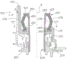
Non-limiting examples of the present disclosure will be described below. The following examples are given with reference to the accompanying drawings, in which fig. 1 to 3 are cross-sectional views of three different examples of the front and rear view mirror assembly for a motor vehicle.
Detailed Description
Fig. 1 and 2 correspond to a first and a second example of this front and rear view mirror assembly of the hollow shaft type, also known as the quarter turn lock (also known as the "rotary") type, for motor vehicles. Fig. 3 corresponds to a third example of this front and rear view mirror assembly, of the type known as swivel (swival), for a motor vehicle.
Referring generally to fig. 1-3, the front and rear view mirror assembly 100 includes a mirror base 200 mounted to a motor vehicle body (not shown) and a mirror housing 300 for receiving a mirror pane (not shown). The mirror housing 300 is rotatably mounted to the mirror base 200 such that it can rotate about a mirror rotation axis X according to at least two predetermined angular positions (i.e., a non-driven retracted position in which the mirror housing 300 is folded along the longitudinal axis of the vehicle and a driven extended position in which the mirror housing 300 is extended laterally from the vehicle.
A non-metallic cylindrical spring 400 made of an elastic material is disposed between the mirror base 200 and the mirror housing 300. The first and second examples shown in fig. 1 and 2 differ from the third example shown in fig. 3 mainly in the constraint of the non-metallic spring 400.
In the example of an axle-type rearview mirror assembly shown in fig. 1 and 2, a non-metallic spring 400 is disposed about an axle 500. The shaft 500 is fixedly attached to the mirror base 200, although the shaft 500 may be removably attached to the mirror base 200. The non-metallic spring 400 is configured to be partially housed into the mirror housing 300, as shown.
In the example of a hollow shaft type rearview mirror assembly shown in fig. 1 and 2, the non-metallic spring 400 has a lower end 410 and an upper end 420, the lower end 410 being constrained by the base element 360 of the mirror housing 300 and the upper end 420 being constrained by the upper flange 510 of the shaft 500 described above.
In the example of a swivel-type rearview mirror assembly shown in fig. 3, the shaft 500 is integrally formed with the mirror base. In this particular embodiment, the non-metallic springs 400 are disposed about a pivot member 600 that is part of the mirror base 200. In this example, the lower end 410 of the non-metal spring 400 is constrained by the base element 360 of the mirror housing 300, while the upper end 420 of the non-metal spring 400 is constrained by a flange or washer 210 that is fixedly attached to the upper end of the pivot member 600.
Both examples share the arrangement of non-metallic springs 400 between the mirror base 200 and the mirror housing 300. Thus, the non-metallic spring 400 exerts an axial spring force between the mirror base 200 and the mirror housing 300 that is different from the axial spring force when the mirror housing 300 is rotated. Specifically, the axial spring force exerted by the non-metallic spring 400 is different at least between the non-actuated retracted position and the actuated extended position of the mirror housing 300.
In both examples shown in fig. 1-3, the mirror housing 300 has a first guide portion 350. The first guide portion 350 is configured for contacting a first contact area 450 of the non-metallic spring 400 located at a lower portion of the non-metallic spring. On the other hand, the mirror base 200 has a second guide portion 250. The second guide portion 250 is configured for contacting a second contact area 460 of the non-metallic spring 400 located at an upper portion of the non-metallic spring.
When the user rotates the mirror housing 300 with respect to the mirror base 200 manually or automatically by an electric drive mechanism, a compressive stress is applied to the non-metallic spring 400 in a direction substantially parallel to the mirror rotation axis X, resulting in a bending stress of the non-metallic spring 400. The force exerted by the non-metallic spring 400 resists rotation of the mirror housing 300 relative to the mirror base 200.
The non-metallic spring 400 has a deformable portion 405 formed between the first and second contact regions 250, 350. The guide portions 350, 250 are arranged such that when the deformable portion 405 is pressed by the mirror housing 300 while moving toward the mirror base 200, the deformable portion 405 of the non-metallic spring 400 deforms according to the outward vertical direction (as indicated by arrow Y in the drawing) of the non-metallic spring 400, as will be explained further below.
The controlled deformation of the deformable portion 405 of the non-metallic spring 400 is caused by movement of the mirror housing 300 towards the mirror base 200. This occurs due to the sliding (slippage) of the bevel (not shown) of the teeth in the mirror base 200 compared to the corresponding bevel (not shown) of the teeth formed in the mirror housing 300 when the mirror housing 300 is rotated relative to the mirror base 200.
The guide portions 250, 350 in both examples in fig. 1, 2 and 3, respectively, are configured to deform the deformable portion 405 of the non-metallic spring 400 in an outward direction (as indicated by the aforementioned arrow Y) of the non-metallic spring 400 substantially perpendicular to the mirror rotation axis X.
The deformation of the spring deformable portion 405 in the outward direction provides a very effective spring action as the mirror housing 300 rotates relative to the mirror base 200. This advantageously enables reduced costs due to manufacturing process and material costs.
Two examples of different deformable portions 405 of a non-metallic spring 400 are shown in fig. 1-3.
In fig. 1, the deformable portion 405 of the non-metallic spring 400 includes an annular groove formed in an outer surface of the non-metallic spring 400. The annular groove defining deformable portion 405 shown in fig. 1 is considered to be a recess in the cross-sectional area of non-metallic spring 400.
In fig. 2, the deformable portion 405 of the non-metallic spring 400 includes an annular protrusion or bead formed in the outer surface of the non-metallic spring 400 and protruding outward and a corresponding annular groove formed in the inner surface of the non-metallic spring 400. The annular protrusion or bead and the annular groove shown in fig. 2, which define the deformable portion 405, are considered to be a recess and a protrusion, respectively, in the cross-sectional area of the non-metallic spring 400.
In fig. 3, the deformable portion 405 of the non-metallic spring 400 includes an annular groove formed in the inner surface of the non-metallic spring 400. The annular groove defining deformable portion 405 shown in fig. 3 is considered to be a recess in the cross-sectional area of non-metallic spring 400.
While only a few examples have been disclosed herein, other alternatives, modifications, uses, and/or equivalents are possible. For example, the non-metallic springs disclosed therein are deformable in a direction outward of the non-metallic springs. However, there may be the following: the non-metallic spring may be deformable in a direction inward of the non-metallic spring. On the other hand, the curved shape of the non-metallic spring when deformed may be convex or concave. In addition, the deformable portion of the non-metallic spring may include one or more grooves and one or more protrusions. It is also contemplated that the outer or inner surface of the deformable portion of the non-metallic spring has the same configuration, i.e., one or more grooves or one or more protrusions, but the outer or inner surface of the deformable portion may have both grooves and protrusions. Finally, the dimensions (e.g., height, thickness, diameter, etc.) of the non-metallic spring and the dimensions of the first guide portion in the mirror housing and the second guide portion in the mirror base will depend on the requirements and the non-metallic material selected.
Accordingly, all possible combinations of the described examples of the front and rear view mirror assemblies are thus encompassed. The scope of the present disclosure should not be limited by the particular examples disclosed herein above, but should be determined only by a fair reading of the claims.
Claims (11)
1. A rearview mirror assembly (100) for a motor vehicle, said mirror assembly (100) comprising:
a mirror base (200) adapted to be mounted to a motor vehicle;
a mirror housing (300) rotatably mounted to the mirror base (200) such that the mirror housing (300) is selectively rotatable about a mirror rotation axis (X) between a non-driven retracted position and a driven extended position;
a non-metallic spring (400) arranged to provide an axial spring force between the mirror base (200) and the mirror housing (300), the axial spring force exerted by the non-metallic spring (400) differing at least between the non-driven retracted position and the driven extended position; and
a first guide portion (350) and a second guide portion (250), the first guide portion (350) for contacting a first contact area (450) of the non-metallic spring (400), the second guide portion (250) for contacting a second contact area (460) of the non-metallic spring (400),
whereby the first guide portion (350) and the second guide portion (250) are configured such that at least one deformable portion (405) of the non-metallic spring (400) located between the first contact area (450) and the second contact area (460) deforms in a direction (Y) substantially perpendicular to the mirror rotation axis (X) during rotation of the mirror housing (300) relative to the mirror base (200) between the non-driven retracted position and the driven extended position.
2. The rearview mirror assembly (100) of claim 1, wherein said first guide portion (350) is associated with one of said mirror housing (300) or said mirror base (200) and said second guide portion (250) is associated with the other of said mirror housing (300) or said mirror base (200).
3. Rearview mirror assembly (100) according to claim 1 or 2, wherein said rearview mirror assembly (100) comprises a shaft (500), said non-metallic spring (400) being arranged around said shaft (500).
4. The rearview mirror assembly (100) of claim 3, wherein said mirror base (200) is integrally formed with said shaft (500).
5. The rearview mirror assembly (100) of claim 3, wherein said mirror base (200) is removably attached to said shaft (500).
6. The rearview mirror assembly (100) of any one of claims 1, 2, 4 or 5, wherein said at least one deformable portion (405) of said non-metallic spring (400) between said first contact area (450) and said second contact area (460) comprises at least one of a groove and a protrusion.
7. The rearview mirror assembly (100) of claim 6, wherein at least one of said groove and said protrusion is formed in at least one of an inner surface and an outer surface of said non-metallic spring (400).
8. Rearview mirror assembly (100) according to any one of claims 1, 2, 4, 5 or 7, wherein said non-metallic spring (400) is at least substantially cylindrical in shape and adapted to be arranged around at least a portion of at least one of said mirror housing (300) and said mirror base (200).
9. The rearview mirror assembly (100) of any one of claims 1, 2, 4, 5, or 7, wherein said first guide portion (350) and said second guide portion (250) are configured such that said deformable portion (405) of said non-metallic spring (400) deforms in a direction (Y) outward of said non-metallic spring (400) during rotation of said mirror housing (300) relative to said mirror base (200) between said non-actuated retracted position and said actuated extended position.
10. Rearview mirror assembly (100) according to any one of claims 1, 2, 4, 5 or 7, wherein said non-metallic spring (400) is a resilient element.
11. The rearview mirror assembly (100) of any one of claims 1, 2, 4, 5, or 7, wherein said rearview mirror assembly (100) further comprises at least one of: (i) a lighting module; (ii) an optical sensor module; (iii) a motor configured to provide rotation of the mirror housing (300) about the mirror base (200) between the non-driven retracted position and the driven extended position; (iv) a mirror pane received in the mirror housing (300) and positioned to provide a substantially rearward view to a vehicle operator when the mirror housing (300) is in the drive extended position; (v) an anti-glare mirror pane housed in the mirror housing (300) and positioned to provide a substantially rearward view to a vehicle operator when the mirror housing (300) is in the drive extended position; (vi) a mirror pane including a heating element housed in the mirror housing (300) and positioned to provide a vehicle operator with a substantially rearward view when the mirror housing (300) is in the drive extended position; (vii) a ground-based self-test mirror housed in the mirror housing (300) and positioned to provide the vehicle operator with substantial vision of the vehicle blind spot area when the mirror housing (300) is positioned in the drive extended position; (viii) an antenna in communication with a radio frequency receiving system; (ix) an actuation mechanism configured to provide an orientation of the mirror pane to adjust the rearward field of view of the vehicle driver; and (x) an outdoor temperature sensing device configured to sense an outdoor temperature of the vehicle.
Applications Claiming Priority (2)
| Application Number | Priority Date | Filing Date | Title |
|---|---|---|---|
| EP14193145.1A EP3020605B1 (en) | 2014-11-14 | 2014-11-14 | Rear-view mirror assembly for motor vehicles |
| EP14193145.1 | 2014-11-14 |
Publications (2)
| Publication Number | Publication Date |
|---|---|
| CN105599685A CN105599685A (en) | 2016-05-25 |
| CN105599685B true CN105599685B (en) | 2020-02-28 |
Family
ID=51897175
Family Applications (1)
| Application Number | Title | Priority Date | Filing Date |
|---|---|---|---|
| CN201510778618.5A Active CN105599685B (en) | 2014-11-14 | 2015-11-13 | Rearview mirror assembly for motor vehicle |
Country Status (4)
| Country | Link |
|---|---|
| US (1) | US9845054B2 (en) |
| EP (1) | EP3020605B1 (en) |
| JP (1) | JP6510385B2 (en) |
| CN (1) | CN105599685B (en) |
Families Citing this family (2)
| Publication number | Priority date | Publication date | Assignee | Title |
|---|---|---|---|---|
| DE102017129186B4 (en) * | 2017-12-07 | 2021-07-01 | Motherson Innovations Company Limited | Rearview device for a motor vehicle, assembly method therefor and motor vehicle with a rearview device |
| US11691568B2 (en) | 2019-08-16 | 2023-07-04 | Ficosa North America Corporation | Articulating visual aid winglet |
Citations (4)
| Publication number | Priority date | Publication date | Assignee | Title |
|---|---|---|---|---|
| GB1008912A (en) * | 1961-08-26 | 1965-11-03 | Cornelis Franciscus Henke | Hollow rubber spring |
| GB2041857B (en) * | 1979-01-29 | 1982-12-15 | Magnatex Ltd | Vehicle rear-view mirror mounting arrangement |
| CN101987598A (en) * | 2009-07-30 | 2011-03-23 | 比亚迪股份有限公司 | Rearview mirror folder structure and manual and electric exterior rearview mirrors with structure |
| CN102219002A (en) * | 2010-04-15 | 2011-10-19 | 市光工业株式会社 | Vehicle outside mirror device |
Family Cites Families (11)
| Publication number | Priority date | Publication date | Assignee | Title |
|---|---|---|---|---|
| JPS5858948U (en) * | 1981-10-16 | 1983-04-21 | トヨタ自動車株式会社 | Car mirror device |
| US4523735A (en) | 1984-01-30 | 1985-06-18 | Delbar Products, Inc. | Mirror swing lock mechanism |
| JPH01144142U (en) * | 1988-03-14 | 1989-10-03 | ||
| JPH0535878Y2 (en) * | 1988-08-31 | 1993-09-10 | ||
| JPH0636987U (en) * | 1992-10-20 | 1994-05-17 | 市光工業株式会社 | Moderation mechanism of automobile door mirror |
| NL1016915C2 (en) | 2000-12-19 | 2002-06-21 | Iku Holding Montfoort Bv | Hinge actuator. |
| FR2845052B1 (en) | 2002-08-06 | 2005-06-24 | Fico Mirrors | ASSEMBLY FOR THE ARTICULATED CONNECTION OF A RETROVISOR MIRROR |
| EP1561642A1 (en) | 2004-02-03 | 2005-08-10 | Fico Mirrors, SA | Articulated connection for a rearview mirror |
| US7207684B2 (en) | 2005-06-15 | 2007-04-24 | Basf Corporation | Exterior mirror assembly isolated by elastomeric material |
| EP1926631B1 (en) | 2005-09-12 | 2008-12-17 | Visiocorp Patents S.à.r.l. | Adjustable mirror |
| JP4985276B2 (en) * | 2007-09-27 | 2012-07-25 | 市光工業株式会社 | Outside mirror device for vehicle |
-
2014
- 2014-11-14 EP EP14193145.1A patent/EP3020605B1/en active Active
-
2015
- 2015-11-10 JP JP2015220133A patent/JP6510385B2/en active Active
- 2015-11-13 CN CN201510778618.5A patent/CN105599685B/en active Active
- 2015-11-13 US US14/940,524 patent/US9845054B2/en active Active
Patent Citations (4)
| Publication number | Priority date | Publication date | Assignee | Title |
|---|---|---|---|---|
| GB1008912A (en) * | 1961-08-26 | 1965-11-03 | Cornelis Franciscus Henke | Hollow rubber spring |
| GB2041857B (en) * | 1979-01-29 | 1982-12-15 | Magnatex Ltd | Vehicle rear-view mirror mounting arrangement |
| CN101987598A (en) * | 2009-07-30 | 2011-03-23 | 比亚迪股份有限公司 | Rearview mirror folder structure and manual and electric exterior rearview mirrors with structure |
| CN102219002A (en) * | 2010-04-15 | 2011-10-19 | 市光工业株式会社 | Vehicle outside mirror device |
Also Published As
| Publication number | Publication date |
|---|---|
| EP3020605B1 (en) | 2018-04-11 |
| JP2016104621A (en) | 2016-06-09 |
| EP3020605A1 (en) | 2016-05-18 |
| US9845054B2 (en) | 2017-12-19 |
| US20160137131A1 (en) | 2016-05-19 |
| JP6510385B2 (en) | 2019-05-08 |
| CN105599685A (en) | 2016-05-25 |
Similar Documents
| Publication | Publication Date | Title |
|---|---|---|
| CN106985755B (en) | Folding rear-view mirror assembly for a motor vehicle | |
| US9758100B2 (en) | Folding rearview mirror for motor vehicles | |
| EP2421729B2 (en) | A windscreen wiper device | |
| CN105599685B (en) | Rearview mirror assembly for motor vehicle | |
| EP3189995B1 (en) | Slide-on-rod assembly for a vehicle sun visor | |
| US20180244300A1 (en) | Adjustable steering column for motor vehicles with energy absorber for vehicle crashes | |
| US6923490B2 (en) | Slidable sun visor assembly | |
| EP3481682B1 (en) | A windscreen wiper device | |
| KR101199181B1 (en) | sun-visor of vehicles | |
| US9090231B2 (en) | Wiper blade apparatus including fool-proof assembly structure | |
| EP3401139B1 (en) | Vanity mirror assembly for a vehicle sun visor | |
| US10953803B2 (en) | Fold rear-view mirror assembly for motor vehicles | |
| US9855922B2 (en) | Automatic integrated automobile windshield wiper lifting device | |
| EP2902263B1 (en) | Rear view mirror assembly for motor vehicles | |
| JP2006290199A (en) | Belt molding | |
| KR20170010196A (en) | Pumping device of seat for vehicle | |
| EP3653442B1 (en) | Actuator for an electric folding rear-view mirror for motor vehicles | |
| WO2020260511A1 (en) | Main body element of a sun visor assembly, sun visor assembly having such a main body element, and method for assembling a sun visor | |
| EP3676135B1 (en) | A windscreen wiper device | |
| KR200172296Y1 (en) | Wiper depressed parking device for a car | |
| CN117400701A (en) | Sun visor assembly for vehicle | |
| KR20110061394A (en) | Sun-visor of vehicles |
Legal Events
| Date | Code | Title | Description |
|---|---|---|---|
| C06 | Publication | ||
| PB01 | Publication | ||
| SE01 | Entry into force of request for substantive examination | ||
| SE01 | Entry into force of request for substantive examination | ||
| GR01 | Patent grant | ||
| GR01 | Patent grant |