CN105467652B - Polarizing plate, liquid crystal display device and organic electroluminescent display device - Google Patents
Polarizing plate, liquid crystal display device and organic electroluminescent display device Download PDFInfo
- Publication number
- CN105467652B CN105467652B CN201510627365.1A CN201510627365A CN105467652B CN 105467652 B CN105467652 B CN 105467652B CN 201510627365 A CN201510627365 A CN 201510627365A CN 105467652 B CN105467652 B CN 105467652B
- Authority
- CN
- China
- Prior art keywords
- film
- polarizing
- protective film
- polarizing plate
- layer
- Prior art date
- Legal status (The legal status is an assumption and is not a legal conclusion. Google has not performed a legal analysis and makes no representation as to the accuracy of the status listed.)
- Active
Links
Images


Classifications
-
- G—PHYSICS
- G02—OPTICS
- G02F—OPTICAL DEVICES OR ARRANGEMENTS FOR THE CONTROL OF LIGHT BY MODIFICATION OF THE OPTICAL PROPERTIES OF THE MEDIA OF THE ELEMENTS INVOLVED THEREIN; NON-LINEAR OPTICS; FREQUENCY-CHANGING OF LIGHT; OPTICAL LOGIC ELEMENTS; OPTICAL ANALOGUE/DIGITAL CONVERTERS
- G02F1/00—Devices or arrangements for the control of the intensity, colour, phase, polarisation or direction of light arriving from an independent light source, e.g. switching, gating or modulating; Non-linear optics
- G02F1/01—Devices or arrangements for the control of the intensity, colour, phase, polarisation or direction of light arriving from an independent light source, e.g. switching, gating or modulating; Non-linear optics for the control of the intensity, phase, polarisation or colour
- G02F1/13—Devices or arrangements for the control of the intensity, colour, phase, polarisation or direction of light arriving from an independent light source, e.g. switching, gating or modulating; Non-linear optics for the control of the intensity, phase, polarisation or colour based on liquid crystals, e.g. single liquid crystal display cells
- G02F1/133—Constructional arrangements; Operation of liquid crystal cells; Circuit arrangements
- G02F1/1333—Constructional arrangements; Manufacturing methods
- G02F1/1335—Structural association of cells with optical devices, e.g. polarisers or reflectors
- G02F1/133528—Polarisers
-
- G—PHYSICS
- G02—OPTICS
- G02B—OPTICAL ELEMENTS, SYSTEMS OR APPARATUS
- G02B5/00—Optical elements other than lenses
- G02B5/30—Polarising elements
- G02B5/3025—Polarisers, i.e. arrangements capable of producing a definite output polarisation state from an unpolarised input state
- G02B5/3033—Polarisers, i.e. arrangements capable of producing a definite output polarisation state from an unpolarised input state in the form of a thin sheet or foil, e.g. Polaroid
Abstract
The invention provides a polarizing plate which is thin, can restrain dimensional change generated when heating is applied, and can restrain appearance defects such as cracks generated on the polarizing film under the environment of repeated high temperature and low temperature. The polarizing plate has a protective film laminated on at least one surface of a polarizing film, the polarizing film has a thickness of 10 [ mu ] m or less, and the polarizing film has a puncture strength P per unit film thickness of 3.6 gf/[ mu ] m or more.
Description
Technical Field
The invention relates to a polarizing plate, a liquid crystal display device and an organic electroluminescence display device.
Background
Polarizing plates are widely used as elements for providing polarization or elements for detecting polarization in display devices such as liquid crystal display devices. A polarizing plate is generally configured by bonding a protective film to one or both surfaces of a polarizing film using an adhesive. In recent years, thinning of polarizing plates has been required along with thinning of liquid crystal display devices.
Documents of the prior art
Patent document
Patent document 2 patent No. 5324316 (Japanese patent laid-open publication No. 2010-9027)
Disclosure of Invention
The invention provides a polarizing plate which is thin, can inhibit dimensional change generated during heating, and can inhibit appearance defects such as cracks generated on the polarizing film under the environment of repeated high temperature and low temperature.
The invention provides the following polarizing plate, liquid crystal display device and organic electroluminescent display device.
[1] A polarizing plate comprising a polarizing film and a protective film laminated on at least one side of the polarizing film,
the thickness of the polarizing film is 10 μm or less, and the puncture strength (strength of し prick) P per unit film thickness of the polarizing film is 3.6gf/μm or more.
[2] The polarizing plate according to [1], wherein the protective film of the polarizing plate is subjected to a cold thermal shock test in which the protective film is repeatedly held at-40 ℃ for 30 minutes and at 85 ℃ for 30 minutes, and after a change in strain of the protective film between-40 ℃ and 85 ℃ is constant, a change in strain a (μ) between-40 ℃ and 85 ℃ in a direction parallel to a transmission axis direction of the polarizing film of the protective film and the puncture strength P (gf/μm) satisfy the following formula (1):
1> (amount of change in strain A-540)/(puncture strength P.times.21) (1).
[3] The polarizing plate according to [1] or [2], wherein the protective film of the polarizing plate is subjected to a cold-hot impact test in which the protective film is repeatedly held at-40 ℃ for 30 minutes and at 85 ℃ for 30 minutes, and after a change in strain of the protective film between-40 ℃ and 85 ℃ reaches a certain value, a change in strain B (μ) between before and at 85 ℃ after the cold-hot impact test and the puncture strength P (gf/μm) satisfy the following formula (2):
1> (amount of change in strain B + 25)/(puncture strength P × 42) (2).
[4] The polarizing plate according to any one of [1] to [3], wherein the protective film of the polarizing plate has a tensile elastic modulus of 1000 to 10000MPa at 23 ℃ in a direction parallel to a transmission axis direction of the polarizing film.
[5] The polarizing plate according to [4], wherein a strength H of the protective film of the polarizing plate in a direction parallel to a transmission axis direction of the polarizing film is 10 to 500N/mm, and the strength H is a product of a tensile elastic modulus and a thickness of the protective film.
[6] The polarizing plate according to any one of [1] to [5], wherein a shrinkage force per 2mm width in an absorption axis direction of the polarizing film is 2N or less when the polarizing film is held at a temperature of 80 ℃ for 240 minutes.
[7] A liquid crystal display device comprising the polarizing plate according to any one of [1] to [6] laminated on a liquid crystal cell via an adhesive layer,
the adhesive layer has a storage elastic modulus of 100 to 1000KPa at 23 ℃.
[8] An organic electroluminescent display device comprising the polarizing plate according to any one of [1] to [6] laminated on an organic electroluminescent display via an adhesive layer,
the adhesive layer has a storage elastic modulus of 100 to 1000KPa at 23 ℃.
The present invention provides a polarizing plate which is thin and has a small shrinkage rate when heat is applied. Further, a polarizing plate excellent in durability is provided in which cracks generated in the polarizing plate are suppressed under an environment of repeated high temperature and low temperature. The polarizing plate of the present invention has a small shrinkage rate, and therefore, even when used in a liquid crystal panel having a narrow frame, the polarizing plate can prevent the end portion of the polarizing plate from entering the visible region due to the shrinkage of the polarizing plate in a high-temperature environment.
Drawings
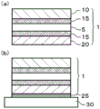
Fig. 1(a) is a schematic cross-sectional view showing an example of the layer structure of the polarizing plate of the present invention, and fig. 1(b) is a schematic cross-sectional view showing an example of the layer structure of the adhesive layer-attached polarizing plate of the present invention and the polarizing plate-bonded glass substrate.
Fig. 2 is a schematic view showing a method for measuring the strain of the protective film in the thermal shock test.
Fig. 3 shows an example of the measurement result of the strain of the protective film in the thermal shock test.
Detailed Description
[ polarizing plate ]
The polarizing plate of the present invention is characterized in that a protective film is laminated on at least one surface of a polarizing film, the polarizing film has a thickness of 10 [ mu ] m or less, and the polarizing film has a puncture strength P per unit film thickness of 3.6 gf/[ mu ] m or more.
The protective film of the polarizing plate is subjected to a cold-heat impact test in which the protective film is repeatedly held at-40 ℃ for 30 minutes and at 85 ℃ for 30 minutes, and after the amount of change in strain of the protective film between-40 ℃ and 85 ℃ has reached a certain value, the amount of change in strain A (μ) between-40 ℃ and 85 ℃ occurring in the direction parallel to the transmission axis direction of the polarizing film in the protective film and the puncture strength P (gf/μm) per unit film thickness of the polarizing film preferably satisfy the following formula (1). Here, the term "the amount of change in strain is constant" means that when the temperature is maintained at-40 ℃ for 30 minutes and 85 ℃ for 30 minutes, the difference in the amount of change in strain is 5% or less in 5 consecutive cycles.
1> (amount of change in strain A-540)/(puncture Strength P X21) (1)
In the graph in which the puncture strength P is represented on the abscissa and the strain variation a is represented on the ordinate, the polarizer in the region in which the puncture strength P and the strain variation a satisfy the above expression (1) can suppress the occurrence of cracks in the polarizing film in the cold-heat impact test.
In the formula (1), the amount of change in strain a is preferably 100 to 1000, and more preferably 750 or less. If the amount of change a in strain is less than 100, the amount of change in dimension becomes smaller than that of glass, and as a result, strain tends to be generated. When the strain change amount a is greater than 1000, the puncture strength P per unit film thickness of the polarizing film (hereinafter also referred to as strength P) is not extremely large, and it tends to be difficult to prevent cracking of the polarizing film. The strength P is preferably 4.0gf/μm or more, more preferably 5.0gf/μm or more, and still more preferably 5.5gf/μm or more. The strength P is usually 15.0gf/μm or less, preferably 10.0gf/μm or less, more preferably 7.0gf/μm or less, and still more preferably 6.7gf/μm or less. If the strength P is less than 3.6gf/μm, the polarizing film tends to be easily cracked. On the other hand, if the strength P is more than 15.0gf/μm, the orientation degree of the polarizing film tends to be low, and the polarization degree tends to be low. If the numerical value is larger than 1 instead of the above formula (1), the rate of occurrence of cracks in the polarizing film increases, and the length of the generated cracks tends to become longer.
Further, it is preferable that the protective film of the polarizing plate is subjected to a cold-heat impact test in which the protective film is repeatedly held at-40 ℃ for 30 minutes and at 85 ℃ for 30 minutes, and after the amount of change in strain of the protective film between-40 ℃ and 85 ℃ has reached a certain value, the amount of change in strain B (μ) between 85 ℃ and the puncture strength P (gf/μm) per unit film thickness of the polarizing film before the cold-heat impact test satisfy the following formula (2).
1> (amount of change in strain B + 25)/(puncture Strength P X42) (2)
In the graph in which the puncture strength P is represented on the horizontal axis and the strain variation B is represented on the vertical axis, and the puncture strength P and the strain variation B satisfy the above expression (2), the polarizing plate in the region in which the puncture strength P and the strain variation B satisfy the above expression (2) can suppress the occurrence of cracks in the polarizing film in the cold and hot impact test.
In the above formula (2), the amount of change in strain B is preferably in the range of 0 to 400. When the amount of change in strain B is less than 0, the strain with the glass increases when the protective film expands, and the polarizing film tends to crack easily. When the amount of change in strain B is larger than 400, strain is generated by shrinkage, and therefore, cracking of the polarizing film tends to occur easily. If the numerical value is larger than 1 without satisfying the formula (2), the rate of occurrence of cracks in the polarizing film increases, and the length of the generated cracks tends to increase.
In the above equations (1) and (2), the average value of the 1 st protective film and the 2 nd protective film is applied when the protective film (1 st protective film) is laminated on one surface of the polarizing film and the other protective film (2 nd protective film) is laminated on the other surface of the polarizing film with respect to the amount of strain a and the amount of strain B.
By using the above-mentioned formulas (1) and (2) as an index for suppressing the cracking of the polarizing film with the protective film, the tendency of the polarizing film to crack can be found with high accuracy even when the difference in tensile elastic modulus between the protective films to be compared is small as compared with the conventional method using the tensile elastic modulus of the protective film as an index.
The protective film of the polarizing plate preferably has a tensile elastic modulus of 1000 to 10000MPa, more preferably 1500 to 8000MPa, in an environment at 23 ℃ in a direction parallel to the transmission axis direction of the polarizing film. If the tensile elastic modulus is less than 1000MPa, the shrinkage of the polarizing plate cannot be suppressed, and the amount of dimensional change in a high-temperature environment tends to increase. The higher the tensile elastic modulus, the better, and generally, the film for optical use which can be obtained is 10000MPa or less. The protective film may be a stretched film or an unstretched film as long as the tensile elastic modulus in the direction parallel to the transmission axis direction of the polarizing film when laminated with the polarizing film is within the above range.
The polarizing plate preferably has a strength H in a direction parallel to the transmission axis direction of the polarizing film, which is obtained as a product of the tensile elastic modulus and the thickness of the protective film, of 10 to 500N/mm, more preferably 50 to 300N/mm. If the strength H is less than 10N/mm, shrinkage of the polarizing plate cannot be suppressed, and the amount of dimensional change in a high-temperature environment tends to increase, and if it is more than 500N/mm, the tensile elastic modulus of a general optical film needs to be increased in thickness, and it tends to be difficult to make the polarizing plate thinner. When the 1 st protective film is laminated on one surface of the polarizing film and the 2 nd protective film is laminated on the other surface, the strength H is the total value of the 1 st protective film and the 2 nd protective film.
(1) Polarizing film
The polarizing film may be one in which a dichroic dye is adsorbed on a uniaxially stretched polyvinyl alcohol resin layer and oriented. When the thickness of the polarizing film is generally 20 μm or less, the polarizing plate can be made thin. In the present invention, a polarizing film having a thickness of 10 μm or less is used, and the thickness of the polarizing film is preferably 8 μm or less. In addition, the thickness of the polarizing film is usually 2 μm or more.
As the polyvinyl alcohol resin, a resin obtained by saponifying a polyvinyl acetate resin can be used. As the polyvinyl acetate-based resin, in addition to polyvinyl acetate which is a homopolymer of vinyl acetate, a copolymer of vinyl acetate and another monomer copolymerizable therewith can be exemplified. Examples of the other monomer copolymerizable with vinyl acetate include unsaturated carboxylic acids, olefins, vinyl ethers, unsaturated sulfonic acids, and acrylamides having an ammonium group.
The saponification degree of the polyvinyl alcohol resin may be in the range of 80 mol% or more, preferably in the range of 90 to 99.5 mol%, and more preferably in the range of 94 to 99 mol%. The polyvinyl alcohol resin may be a partially modified polyvinyl alcohol, and examples thereof include a polyvinyl alcohol resin obtained by using an olefin such as ethylene or propylene; unsaturated carboxylic acids such as acrylic acid, methacrylic acid, and crotonic acid; modified polyvinyl alcohol obtained by modifying an alkyl ester of an unsaturated carboxylic acid, acrylamide, or the like. The polyvinyl alcohol resin preferably has an average polymerization degree of 100 to 10000, more preferably 1500 to 8000, and still more preferably 2000 to 5000.
The dichroic dye contained (adsorbed and aligned) in the polarizing film may be iodine or a dichroic organic dye, and conventionally known dichroic dyes may be used. Only 1 kind of dichroic dye may be used, or 2 or more kinds may be used.
In the present invention, a polarizing film having a thickness of 10 μm or less and a puncture strength per unit film thickness of 3.6gf/μm or more is used as the polarizing film. The puncture strength per unit film thickness of the polarizing film is a strength at which the polarizing film is punctured perpendicularly by a puncturing jig and the polarizing film is cracked along its tensile axis (absorption axis), and can be measured, for example, by a compression tester equipped with a load cell. Examples of the compression tester include a hand-held compression tester "KES-G5" manufactured by Kato Tech corporation, and a small bench tester "EZ Test (registered trademark)" manufactured by shimadzu corporation.
The polarizing film used for the measurement may be a polarizing film before polarizing by laminating a protective film, or a polarizing film in which a protective film is removed from a polarizing plate obtained by laminating a protective film with an adhesive or the like.
As a method for removing the protective film from the polarizing plate, a method of dissolving the protective film with a solvent if the polarizing film is not damaged; a method of peeling the protective film by immersing the protective film in a solution having a good affinity with the adhesive, and the like.
The measurement was carried out by holding the polarizing film between 2 sample stages each having a circular hole having a diameter of 15mm or less through which the puncturing jig can pass. The puncture jig is a columnar rod, and preferably includes a puncture needle having a spherical or hemispherical tip that contacts the polarizing film. The diameter of the spherical or semispherical portion of the tip is preferably 0.5mm phi to 5mm phi. In addition, the radius of curvature is preferably greater than 0R and less than 0.7R. The puncture speed of the compression tester is preferably 0.05 cm/sec to 0.5 cm/sec.
The puncture strength can be measured by fixing the test piece to a jig and measuring the strength when the test piece is split at one point horizontally to the stretching direction (the absorption axis direction) when the puncture jig is punctured from the normal direction. The measurement was performed on 5 or more polarizing films, and the average value thereof was determined as the puncture strength. The puncture strength per unit film thickness can be calculated by dividing the measured puncture strength by the film thickness of the polarizing film used for the measurement. This method can quantitatively measure the breaking strength when the polarizing film is stretched in the transmission axis direction and cracked in the absorption axis direction, and therefore can measure the strength in the transmission axis direction which has not been measured so far because the polarizing film is easily cracked.
The puncture strength per unit film thickness can be improved by reducing the stretching ratio in the production of a polarizing film or by performing a drying treatment at a high temperature of about 70 ℃. When the puncture strength per unit film thickness is less than 3.6gf/μm, the rate of occurrence of cracks in the polarizing film tends to be high, and the length of the cracks to be generated tends to be long.
The polarizing plate of the present invention uses a polarizing film having a puncture strength of 3.6gf/μm or more per unit film thickness, and therefore, the polarizing film itself has high strength, and therefore, even when a thin polarizing film has a minute defect, the occurrence of a crack can be suppressed.
The shrinkage force per 2mm width in the absorption axis direction of the polarizing film when the film is held at a temperature of 80 ℃ for 240 minutes is preferably 2N or less. If the shrinkage force is greater than 2N, the amount of dimensional change in a high-temperature environment becomes large, and the shrinkage force of the polarizing film becomes large, so that the polarizing film tends to be easily cracked. If the stretching ratio is reduced or the thickness of the polarizing film is reduced, the shrinkage force of the polarizing film tends to be 2N or less.
(2) Protective film
A protective film is laminated on at least one surface of the polarizing film. When a protective film (1 st protective film) is laminated on one surface of the polarizing film and another protective film (2 nd protective film) is laminated on the other surface, the same protective film as the 1 st protective film may be used as the 2 nd protective film, or another resin film may be used. The 1 st protective film and the 2 nd protective film may be transparent resin films each composed of a thermoplastic resin. Examples of the thermoplastic resin include polyolefin resins such as a chain polyolefin resin and a cyclic polyolefin resin exemplified by a polypropylene resin; cellulose ester resins such as cellulose triacetate and cellulose diacetate; polyester resins such as polyethylene terephthalate, polyethylene naphthalate, and polybutylene terephthalate; a polycarbonate-based resin; (meth) acrylic resins; or mixtures, copolymers, etc. thereof.
The cyclic polyolefin resin is a general term for resins obtained by polymerizing a cyclic olefin as a polymerization unit, and examples thereof include those described in Japanese patent application laid-open Nos. 1-240517, 3-14882, and 3-122137. Specific examples of the cyclic polyolefin resin include ring-opened (co) polymers of cyclic olefins, addition polymers of cyclic olefins, copolymers (typically random copolymers) of linear olefins such as ethylene and propylene with cyclic olefins, graft polymers obtained by modifying these with unsaturated carboxylic acids or derivatives thereof, and hydrogenated products of these. Among these, norbornene-based resins using norbornene-based monomers such as norbornene and polycyclic norbornene-based monomers as cyclic olefins are preferably used.
Various products are commercially available as cyclic polyolefin resins. Examples of commercially available products of cyclic polyolefin resins are represented by trade names, such as "TOPAS" (registered trademark) sold by polyplastic corporation of japan, manufactured by TOPAS ADVANCED POLYMERS GmbH, "ARTON" (registered trademark) sold by JSR corporation, "ZEONOR" (registered trademark) and "ZEONEX" (registered trademark) sold by Zeon corporation of japan, and "APEL" (registered trademark) sold by mitsui chemical corporation.
Further, a commercially available product of a film-formed cyclic polyolefin resin film can be used as the protective film. Examples of commercially available products are all indicated by trade names, and include "ARTON Film" sold by JSR corporation (the "ARTON" is a registered trademark of the company), "escina" (the registered trademark) and "SCA 40" sold by waterlogging chemical industries, and "ZEONOR Film" (the registered trademark) sold by Zeon corporation, japan.
A retardation film to which an arbitrary retardation value is given can be produced by subjecting a cyclic polyolefin resin film produced into a film to stretching such as uniaxial stretching or biaxial stretching, or forming a liquid crystal layer on the film.
The cellulose ester resin is usually an ester of cellulose and a fatty acid. Specific examples of the cellulose ester resin include cellulose triacetate, cellulose diacetate, cellulose tripropionate, and cellulose dipropionate. Further, copolymers thereof and resins obtained by modifying a part of hydroxyl groups with other substituents may also be used. Among them, cellulose triacetate (triacetyl cellulose: TAC) is particularly preferable. Cellulose triacetate is commercially available in a large amount, and is advantageous in terms of availability and cost. Examples of commercially available cellulose triacetate are all shown by trade names, and include "FUJITAC (registered trademark) TD 80", "FUJITAC (registered trademark) TD80 UF", "FUJITAC (registered trademark) TD80 UZ" and "FUJITAC (registered trademark) TD40 UZ" sold by Fuji Flim co, TAC Film "KC 8UX 2M", "KC 2 UA" and "KC 4 UY" manufactured by Konica Minolta co.
Similarly, the cellulose ester resin film thus produced may be stretched such as uniaxial stretching or biaxial stretching, or a liquid crystal layer may be formed on the film, whereby a retardation film having an arbitrary retardation value can be produced.
The (meth) acrylic resin is generally a polymer mainly composed of methacrylic acid ester. The methacrylic resin may be a homopolymer of 1 kind of methacrylic acid ester, or a copolymer of methacrylic acid ester with other methacrylic acid ester or acrylic acid ester. Examples of the methacrylic acid ester include alkyl methacrylates such as methyl methacrylate, ethyl methacrylate and butyl methacrylate, and the number of carbon atoms in the alkyl group is usually about 1 to 4. In addition, cyclopentyl methacrylate, cyclohexyl methacrylate, cycloalkyl methacrylate such as methacrylic acid, aryl methacrylate such as phenyl methacrylate, cycloalkyl methacrylate such as cyclohexylmethyl methacrylate, and aralkyl methacrylate such as benzyl methacrylate may also be used.
Examples of the other polymerizable monomers that can constitute the (meth) acrylic resin include acrylic acid esters, methacrylic acid esters, and polymerizable monomers other than acrylic acid esters. As the acrylic ester, an alkyl acrylate may be used, and specific examples thereof include alkyl acrylates having an alkyl group of 1 to 8 carbon atoms such as methyl acrylate, ethyl acrylate, n-propyl acrylate, isopropyl acrylate, n-butyl acrylate, isobutyl acrylate, t-butyl acrylate, 2-ethylhexyl acrylate, cyclohexyl acrylate, and 2-hydroxyethyl acrylate. The number of carbon atoms in the alkyl group is preferably 1 to 4. In the (meth) acrylic resin, only 1 kind of the acrylic ester may be used alone, or 2 or more kinds may be used in combination.
Examples of the polymerizable monomer other than the methacrylic acid ester and the acrylic acid ester include a monofunctional monomer having 1 polymerizable carbon-carbon double bond in the molecule and a polyfunctional monomer having at least 2 polymerizable carbon-carbon double bonds in the molecule, and a monofunctional monomer is preferably used. Specific examples of the monofunctional monomer include styrene monomers such as styrene, α -methylstyrene, vinyltoluene, halogenated styrene, and hydroxystyrene; vinyl cyanides such as acrylonitrile and methacrylonitrile; unsaturated acids such as acrylic acid, methacrylic acid, maleic anhydride, and itaconic anhydride; maleimides such as N-methylmaleimide, N-cyclohexylmaleimide and N-phenylmaleimide; allyl alcohols such as methallyl alcohol and allyl alcohol; vinyl acetate, vinyl chloride, ethylene, propylene, 4-methyl-1-pentene, 2-hydroxymethyl-1-butene, methyl vinyl ketone, N-vinyl pyrrolidone, N-vinyl carbazole and other monomers.
Specific examples of the polyfunctional monomer include polyunsaturated carboxylic acid esters of polyhydric alcohols such as ethylene glycol dimethacrylate, butanediol dimethacrylate and trimethylolpropane triacrylate; alkenyl esters of unsaturated carboxylic acids such as allyl acrylate, allyl methacrylate, and allyl cinnamate; polyalkenyl esters of polybasic acids such as diallyl phthalate, diallyl maleate, triallyl cyanurate, triallyl isocyanurate, and aromatic polyalkenyl compounds such as divinylbenzene.
The polymerizable monomers other than the methacrylic acid ester and the acrylic acid ester may be used alone in 1 kind or in combination in 2 or more kinds.
The preferred monomer composition of the (meth) acrylic resin is 50 to 100% by weight of an alkyl methacrylate, 0 to 50% by weight of an alkyl acrylate, 0 to 50% by weight of a polymerizable monomer other than these monomers, more preferably 50 to 99.9% by weight of an alkyl methacrylate, 0.1 to 50% by weight of an alkyl acrylate, and 0 to 49.9% by weight of a polymerizable monomer other than these monomers, based on the total amount of the monomers.
In addition, the (meth) acrylic resin may have a ring structure in the main chain of the polymer in order to improve the durability of the film. The ring structure is preferably a heterocyclic structure such as a cyclic acid anhydride structure, a cyclic imide structure, or a lactone ring structure. Specifically, a cyclic acid anhydride structure such as a glutaric anhydride structure or a succinic anhydride structure, a cyclic imide structure such as a glutarimide structure or a succinimide structure, and a lactone ring structure such as butyrolactone or valerolactone may be mentioned. The glass transition temperature of the (meth) acrylic resin can be increased as the content of the ring structure in the main chain is increased. The cyclic acid anhydride structure and the cyclic imide structure can be introduced by a method of introducing a monomer having a cyclic structure such as maleic anhydride or maleimide by copolymerization, a method of introducing a cyclic acid anhydride structure by dehydration and demethanol condensation after polymerization, a method of introducing a cyclic imide structure by reacting an amino compound, and the like. The resin (polymer) having a lactone ring structure can be obtained by a method in which a polymer having a hydroxyl group and an ester group in a polymer chain is prepared, and then the hydroxyl group and the ester group in the obtained polymer are subjected to cyclized condensation by heating in the presence of a catalyst such as an organic phosphorus compound if necessary to form a lactone ring structure.
The polymer having a hydroxyl group and an ester group in the polymer chain can be obtained by using, as a part of the monomers, (meth) acrylic acid esters having a hydroxyl group and an ester group, such as methyl 2- (hydroxymethyl) acrylate, ethyl 2- (hydroxymethyl) acrylate, isopropyl 2- (hydroxymethyl) acrylate, n-butyl 2- (hydroxymethyl) acrylate, and tert-butyl 2- (hydroxymethyl) acrylate. A more specific method for producing a polymer having a lactone ring structure is described in, for example, Japanese patent laid-open No. 2007-254726.
The (meth) acrylic resin can be produced by radical polymerization of a monomer composition containing the above-mentioned monomer. The monomer composition may contain a solvent and a polymerization initiator as necessary.
The (meth) acrylic resin may contain other resins than the (meth) acrylic resin described above. The content of the other resin is preferably 0 to 70% by weight, more preferably 0 to 50% by weight, and still more preferably 0 to 30% by weight. The resin may be, for example, an olefin polymer such as polyethylene, polypropylene, an ethylene-propylene copolymer, or poly (4-methyl-1-pentene); halogen-containing polymers such as vinyl chloride and vinyl chloride resins; styrene polymers such as polystyrene, styrene-methyl methacrylate copolymer, and styrene-acrylonitrile copolymer; polyesters such as polyethylene terephthalate, polybutylene terephthalate, and polyethylene naphthalate; polyarylates formed from aromatic diols and aromatic dicarboxylic acids; biodegradable polyesters such as polylactic acid and polybutylene succinate; a polycarbonate; polyamides such as nylon 6, nylon 66, and nylon 610; a polyacetal; polyphenylene ether; polyphenylene sulfide; polyether ether ketone; polyether nitrile; polysulfones; polyether sulfone; polyoxybenzyl ester; polyamideimide, and the like.
The (meth) acrylic resin may contain rubber particles from the viewpoint of improving the impact resistance and film-forming properties of the film. The rubber particles may be particles composed only of a layer exhibiting rubber elasticity, or may be particles having a multilayer structure having another layer together with the layer exhibiting rubber elasticity. Examples of the rubber elastomer include olefin-based elastic polymers, diene-based elastic polymers, styrene-diene-based elastic copolymers, acrylic elastic polymers, and the like. Among them, acrylic elastic polymers are preferably used from the viewpoint of light resistance and transparency.
The acrylic elastic polymer may be a polymer mainly composed of an alkyl acrylate, that is, containing 50% by weight or more of a constituent unit derived from an alkyl acrylate based on the total amount of monomers. The acrylic elastic polymer may be a homopolymer of an alkyl acrylate, or may be a copolymer containing 50 wt% or more of a constituent unit derived from an alkyl acrylate and 50 wt% or less of a constituent unit derived from another polymerizable monomer.
As the alkyl acrylate constituting the acrylic elastic polymer, an alkyl acrylate having an alkyl group of 4 to 8 carbon atoms is generally used. Examples of the other polymerizable monomers include alkyl methacrylates such as methyl methacrylate and ethyl methacrylate; styrene monomers such as styrene and alkylstyrene; monofunctional monomers such as unsaturated nitriles including acrylonitrile and methacrylonitrile, and alkenyl esters of unsaturated carboxylic acids such as allyl (meth) acrylate and methallyl (meth) acrylate; dienyl esters of dibasic acids such as diallyl maleate; and polyfunctional monomers such as unsaturated carboxylic diesters of glycols such as alkylene glycol di (meth) acrylates.
The rubber particles containing an acrylic elastic polymer are preferably particles having a multilayer structure having a layer of an acrylic elastic polymer. Specifically, there are included particles having a 2-layer structure in which a hard polymer layer mainly composed of an alkyl methacrylate is provided outside a layer of an acrylic elastic polymer; further, the particles have a 3-layer structure comprising a hard polymer layer mainly composed of an alkyl methacrylate on the inner side of the acrylic elastic polymer layer.
Examples of the monomer composition of the alkyl methacrylate-based polymer constituting the hard polymer layer formed on the outer side or the inner side of the acrylic elastic polymer layer are the same as the monomer composition of the alkyl methacrylate-based polymer exemplified as the (meth) acrylic resin, and it is particularly preferable to use the monomer composition mainly containing methyl methacrylate. Such acrylic rubber elastomer particles having a multilayer structure can be produced, for example, by the method described in Japanese patent publication No. 55-27576.
From the viewpoint of film-forming properties of the (meth) acrylic resin, impact resistance of the film, and smoothness of the film surface, the average particle diameter of the rubber particles up to the rubber elastic layer (acrylic elastic polymer layer) contained therein is preferably in the range of 10 to 350 nm. The average particle diameter is more preferably 30nm or more, more preferably 50nm or more, still more preferably 300nm or less, and still more preferably 280nm or less.
The average particle diameter of the rubber particles up to the rubber elastic layer (layer of acrylic elastic polymer) was measured as follows. That is, if such rubber particles are mixed with a (meth) acrylic resin to form a film, and the cross section thereof is dyed with an aqueous solution of ruthenium oxide, only the rubber elastomer layer is colored and observed to be almost circular, and the (meth) acrylic resin of the matrix layer is not dyed. Therefore, a thin section is prepared from the thus-dyed film section using a microtome or the like, and observed with an electron microscope. Next, 100 dyed rubber particles were randomly extracted, and the particle diameters (diameters up to the rubber elastic layer) were calculated, and the number average thereof was defined as the above average particle diameter. The average particle diameter obtained by the measurement in this manner is a number average particle diameter.
In the case where the rubber particles in which the outermost layer is a hard polymer mainly composed of methyl methacrylate and the rubber elastic layer (layer of acrylic elastic polymer) is embedded are mixed with the matrix (meth) acrylic resin, the outermost layer of the rubber particles is mixed with the matrix (meth) acrylic resin. Therefore, when the cross section of the rubber particle is stained with ruthenium oxide and observed with an electron microscope, the rubber particle is observed as a particle excluding the outermost layer. Specifically, in the case of the rubber particles having a 2-layer structure in which the inner layer is an acrylic elastic polymer and the outer layer is a hard polymer mainly composed of methyl methacrylate, the acrylic elastic polymer portion of the inner layer is dyed and observed as particles having a single-layer structure. Further, a 3-layer rubber particle having a structure in which the innermost layer is a hard polymer mainly composed of methyl methacrylate, the intermediate layer is an acrylic elastic polymer, and the outermost layer is a hard polymer mainly composed of methyl methacrylate was observed as a 2-layer particle in which the particle center portion of the innermost layer is not dyed and only the acrylic elastic polymer portion of the intermediate layer is dyed.
From the viewpoint of film-forming properties of the (meth) acrylic resin, impact resistance of the film, and smoothness of the film surface, the rubber particles are preferably blended in a proportion of 3 to 60 wt%, more preferably 45 wt% or less, and even more preferably 35 wt% or less, based on the total amount of the (meth) acrylic resin and the (meth) acrylic resin constituting the (meth) acrylic resin film. When the rubber elastomer particles are more than 60% by weight, dimensional change of the film becomes large, and heat resistance is lowered. On the other hand, although the rubber elastomer particles are less than 3% by weight, the heat resistance of the film is good, but the winding property during film production is poor, and the productivity is lowered in some cases. In the present invention, when particles having a multilayer structure having a layer exhibiting rubber elasticity and another layer are used as the rubber elastomer particles, the weight of the portion composed of the layer exhibiting rubber elasticity and the layer inside the layer is defined as the weight of the rubber elastomer particles. For example, when the acrylic rubber elastomer particles having the 3-layer structure described above are used, the total weight of the acrylic rubber elastic polymer portion in the intermediate layer and the hard polymer portion mainly composed of methyl methacrylate in the innermost layer is defined as the weight of the rubber elastomer particles. When the acrylic rubber elastomer particles having the 3-layer structure are dissolved in acetone, the acrylic rubber elastic polymer portion of the intermediate layer and the hard polymer portion mainly composed of methyl methacrylate of the innermost layer remain as insoluble components, and therefore the weight ratio of the total of the intermediate layer and the innermost layer to the acrylic rubber elastomer particles having the 3-layer structure can be easily determined.
When the (meth) acrylic resin film contains rubber particles, the rubber particle-containing (meth) acrylic resin composition used for producing the film can be obtained by mixing the (meth) acrylic resin and the rubber particles by melt kneading or the like, or can be obtained by a method of first preparing the rubber particles and polymerizing a monomer composition which is a raw material of the (meth) acrylic resin in the presence of the rubber particles.
The (meth) acrylic resin may contain, in addition to the rubber particles, usual additives such as an ultraviolet absorber, an organic dye, a pigment, an inorganic pigment, an antioxidant, an antistatic agent, a surfactant, and the like. Among them, an ultraviolet absorber is preferably used in terms of improving weather resistance. Examples of the ultraviolet absorber include 2, 2' -methylenebis [4- (1,1,3, 3-tetramethylbutyl) -6- (2H-benzotriazol-2-yl) phenol ], 2- (5-methyl-2-hydroxyphenyl) -2H-benzotriazole, 2- [ 2-hydroxy-3, 5-bis (. alpha.,. alpha. -dimethylbenzyl) phenyl ] -2H-benzotriazole, 2- (3, 5-di-tert-butyl-2-hydroxyphenyl) -2H-benzotriazole, 2- (3-tert-butyl-5-methyl-2-hydroxyphenyl) -5-chloro-2H-benzotriazole, 2- (2-tert-butyl-2-hydroxy-phenyl) -5-chloro-2H-benzotriazole, and mixtures thereof, Benzotriazole-based ultraviolet absorbers such as 2- (3, 5-di-tert-butyl-2-hydroxyphenyl) -5-chloro-2H-benzotriazole, 2- (3, 5-di-tert-amyl-2-hydroxyphenyl) -2H-benzotriazole, and 2- (2 '-hydroxy-5' -tert-octylphenyl) -2H-benzotriazole; 2-hydroxybenzophenone-based ultraviolet absorbers such as 2-hydroxy-4-methoxybenzophenone, 2-hydroxy-4-octyloxybenzophenone, 2, 4-dihydroxybenzophenone, 2-hydroxy-4-methoxy-4 '-chlorobenzophenone, 2' -dihydroxy-4-methoxybenzophenone, and 2,2 '-dihydroxy-4, 4' -dimethoxybenzophenone; salicylic acid phenyl ester ultraviolet absorbers such as p-tert-butylphenyl salicylate and p-octylphenyl salicylate; 2, 4-diphenyl-6- (2-hydroxy-4-methoxyphenyl) -1,3, 5-triazine, 2, 4-diphenyl-6- (2-hydroxy-4-ethoxyphenyl) -1,3, 5-triazine, 2, 4-diphenyl- (2-hydroxy-4-propoxyphenyl) -1,3, 5-triazine, 2, 4-diphenyl- (2-hydroxy-4-butoxyphenyl) -1,3, 5-triazine, 2, 4-diphenyl-6- (2-hydroxy-4-hexyloxyphenyl) -1,3, 5-triazine, 2, 4-diphenyl-6- (2-hydroxy-4-octyloxyphenyl) -1,3, 5-triazine, 2, 4-diphenyl-6- (2-hydroxy-4-dodecyloxyphenyl) -1,3, 5-triazine, 2, 4-diphenyl-6- (2-hydroxy-4-benzyloxyphenyl) -1,3, 5-triazine, 2- (2-hydroxy-4- [ 1-octyloxycarbonylethoxy ] phenyl) -4, 6-bis (4-phenylphenyl) -1,3, 5-triazine, 4-bis [ 2-hydroxy-4-butoxyphenyl ] -6- (2, 4-dibutoxyphenyl) 1,3, 5-triazine, 2- [4- [ (2-hydroxy-3- (2' -ethyl) hexyloxy ] -2-hydroxyphenyl ] -4, 6-bis (2, 4-dimethylphenyl) -1,3, 5-triazine, 2- (4, 6-bis (2, 4-dimethylphenyl) -1,3, 5-triazin-2-yl) -5-hydroxyphenyl, 2- [4, 6-bis (2, 4-dimethylphenyl) -1,3, 5-triazin-2-yl ] -5- (octyloxy) phenol, 2- [2, 6-bis (2, 4-dimethylphenyl) -1, and triazine-based ultraviolet absorbers such as 3, 5-triazin-2-yl ] -5-octyloxyphenol, 2- (4, 6-diphenyl-1, 3, 5-triazin-2-yl) -5- [2- (2-ethylhexanoyl) ethoxy ] phenol, and 2,4, 6-tris (2-hydroxy-4-hexyloxy-3-methoxyphenyl) -1,3, 5-triazine, and 2 or more of these may be used as necessary.
Examples of the ultraviolet absorber that can be used include triazine-based ultraviolet absorbers such as "Kemisorb 102" (registered trademark) manufactured by CHEMIPRO KASEI corporation, "ADK STAB (registered trademark) LA 46", "ADK STAB (registered trademark) LAF 70", manufactured by ADEKA corporation, "TINUVIN (registered trademark) 460", "TINUVIN (registered trademark) 405", "TINUVIN (registered trademark) 400", and "TINUVIN (registered trademark) 477", manufactured by sun chemical corporation, "CYASORB (registered trademark) UV-1164" (trade names of the above). Examples of the benzotriazole-based ultraviolet absorbers include "ADK STAB LA 31" and "ADK STAB LA 36" manufactured by ADEKA corporation, "sumirorb (registered trademark) 200", "sumirorb (registered trademark) 250", "sumirorb (registered trademark) 300", "sumirorb (registered trademark) 340" and "sumirorb (registered trademark) 350" manufactured by Sumika Chemtex corporation, "kemiorb 74 (registered trademark)" and "Kemisorb 79" (registered trademark) and "Kemisorb 279" (registered trademark), and "TINUVIN (registered trademark) 99-2", "TINUVIN (registered trademark) 900" and "TINUVIN (registered trademark) 928" (both of which are trade names of the above) manufactured by BASF corporation. When the ultraviolet absorber is contained in the (meth) acrylic resin film, the amount thereof is usually 0.1% by weight or more, preferably 0.3% by weight or more, and more preferably 3% by weight or less based on 100% by weight of the (meth) acrylic resin.
The (meth) acrylic resin film can be produced by a conventionally known film-forming method. The (meth) acrylic resin film may have a multilayer structure, and various conventionally known methods such as a method using a feed block, a method using a multi-manifold die, and the like may be used for the multilayer structure of the (meth) acrylic resin film. Among these, a method of forming a film by laminating through a feed block, performing a multilayer melt extrusion molding from a T-die, and bringing at least one surface of the obtained laminated film into contact with a roll or a belt is preferable because a film having good surface properties is obtained. In particular, from the viewpoint of improving the surface smoothness and surface gloss of the (meth) acrylic resin film, a method of bringing both surfaces of the multilayer film-shaped material obtained by the multilayer melt extrusion molding into contact with a roll surface or a belt surface to form a film is preferable. The roller or the belt used in this case is preferably a mirror surface in order to impart smoothness to the surface of the (meth) acrylic resin film on the surface of the roller or the belt in contact with the (meth) acrylic resin.
The (meth) acrylic resin film may be subjected to a stretching treatment. Stretching treatment is required to obtain a film having desired optical and mechanical properties. Examples of the stretching treatment include uniaxial stretching and biaxial stretching. Examples of the stretching direction include a machine flow direction (MD) of an unstretched film, a direction (TD) orthogonal thereto, and a direction oblique to the machine flow direction (MD). The biaxial stretching may be simultaneous biaxial stretching in which 2 stretching directions are simultaneously stretched, or sequential biaxial stretching in which stretching in a predetermined direction is followed by stretching in the other direction.
The stretching treatment is performed by stretching in the longitudinal direction (machine flow direction: MD) using 2 or more pairs of nip rolls that increase the peripheral speed on the exit side, or by expanding the unstretched film by gripping both side ends thereof with chucks in The Direction (TD) orthogonal to the machine flow direction.
The stretch ratio in the stretching treatment is preferably more than 0% and 300% or less, and more preferably 100 to 250%. If the stretch ratio exceeds 300%, the film thickness becomes too thin and easily breaks, or the workability is lowered. The draw ratio was determined by the following equation.
Stretch magnification (%) (100 × { (length after stretching) - (length before stretching) }/(length before stretching)
From the viewpoint of improving the adhesion to the surface-treated layer and the polarizing film, the absolute value of the plane orientation coefficient Δ P of the stretched (meth) acrylic resin film is preferably 2 × 10⁻⁴The following.
The plane orientation coefficient Δ P is a physical property value which is an index of the orientation state of the molecular chains of the polymer constituting the film, and n is a refractive index in the in-plane slow axis direction (direction in which the in-plane refractive index is the maximum) of the filmxThe refractive index in the in-plane fast axis direction (the direction orthogonal to the in-plane slow axis direction) is nyThe refractive index in the thickness direction of the film is nzThe formula (I) is defined by the following formula.
The plane orientation coefficient Δ P ═ n (n)x+ny)/2-nz
For example, in the case of a film biaxially stretched in MD and TD, a larger absolute value of the plane orientation coefficient Δ P means that the molecular chains of the polymer are oriented more perpendicularly to the thickness direction of the film. In general, the surface orientation coefficient Δ P of a stretched (meth) acrylic resin film takes a negative value.
In addition, in order to impart desired optical properties and mechanical properties, a treatment of laminating a heat-shrinkable film to a (meth) acrylic resin film to shrink the film may be performed instead of or together with the stretching treatment.
In order to improve the adhesion strength between the (meth) acrylic resin film and the polarizing film, an easy adhesion layer may be provided on the surface of the (meth) acrylic resin film facing the polarizing film.
The easy-adhesion layer provided on the surface of the protective film facing the polarizing film may be any layer that can improve the adhesion between the protective film and the adhesive. Examples of the material for forming such an easy adhesion layer include polyester resins, polyurethane resins, and acrylic resins having a polar group in the skeleton and having a relatively low molecular weight and a relatively low glass transition temperature. The polar group present in the skeleton is preferably selected so that the resin is hydrophilic or water-dispersible, and examples thereof include a hydrophilic substituent, an ether bond, a plurality of ether bonds, and the like.
More specific examples of the hydrophilic substituent include a sulfonic acid group, a carboxylic acid group, a phosphoric acid group, and lithium salts, sodium salts, potassium salts, and ammonium salts thereof. The ether bond or the plurality of ether bonds may be structural units introduced by diethylene glycol, triethylene glycol, polyethylene glycol, polypropylene glycol, or the like. The material constituting the easy-adhesion layer can be prepared by introducing a monomer having such a substituent or a structural unit into a polyester-based resin, a polyurethane-based resin, or an acrylic-based resin.
If necessary, a crosslinking agent, an organic or inorganic filler, a surfactant, a lubricant, and the like may be added to the material constituting the easy adhesion layer.
The easy-adhesion agent can be formed by, for example, a method in which a solution containing the material constituting the easy-adhesion layer described above or a solution containing a precursor of such a material and a polymerization initiator (hereinafter, may be referred to as "composition for an easy-adhesion layer") is applied to one surface of a protective film made of a methacrylic resin, and then dried or dried and cured. The easy-adhesion layer may be formed immediately after the protective film made of a methacrylic resin is formed, or may be formed immediately before the easy-adhesion layer is attached to the polarizing film.
The thickness of the easy-adhesion layer after drying or after drying and curing is preferably 0.01 to 5 μm, more preferably 0.03 to 0.6. mu.m. If the easy-adhesion layer is too thin, the adhesion strength between the polarizing film and the protective film becomes insufficient. On the other hand, if the easy-adhesion layer is too thick, the hydrophilicity becomes excessive, and the water resistance of the obtained polarizing plate may be poor.
As a method for coating the composition for an easy-adhesion layer on the surface of the protective film opposite to the polarizing film, a general coating technique using a die coater, a comma coater, a reverse roll coater, a gravure coater, a bar coater, a wire bar coater, a blade coater, an air knife coater, or the like can be used. The method and conditions for drying the composition for an easy-adhesive layer applied are not particularly limited, and for example, a method of drying using a hot air dryer or an infrared dryer can be employed. In addition, when a solution containing a precursor of a material constituting the easy adhesion layer is used as the composition for the easy adhesion layer, a curing step may be provided after drying and curing. In the case of the aging step, the composition for the easy-adhesion layer is cured to some extent by the heat used for drying, and is further cured in the subsequent adhesion step of the polarizing film and the protective film using the adhesive, so that sufficient physical properties can be obtained even when the composition is aged at room temperature.
In order to adjust the affinity of the surface of the protective film provided with the easy-adhesion layer with respect to the adhesive, corona discharge treatment, plasma treatment, ozone blowing, ultraviolet irradiation, flame treatment, chemical agent treatment, and other conventionally known surface treatments may be applied to the surface of the easy-adhesion layer provided on the protective film before the easy-adhesion layer is subsequently bonded to the polarizing film via the adhesive.
The 1 st protective film and the 2 nd protective film may be protective films having both optical functions, such as a luminance improving film.
The brightness enhancement film is used for the purpose of enhancing the brightness of a liquid crystal display device or the like, and examples thereof include a reflection-type polarization separation sheet designed to laminate a plurality of thin films having different refractive index anisotropy to generate anisotropy in reflectance, and a circularly polarized light separation sheet obtained by supporting an oriented film of a cholesteric liquid crystal polymer or an oriented liquid crystal layer thereof on a film substrate.
A surface treatment layer (coating layer) such as a hard coat layer, an antiglare layer, an antireflection layer, an antistatic layer, and an antifouling layer may be formed on the surface of the 1 st protective film and the 2 nd protective film on the opposite side to the polarizing film. A known method can be used for forming the surface treatment layer on the surface of the protective film.
The 1 st protective film and the 2 nd protective film may be the same protective film as each other or different protective films. As examples of the case where the protective film is different, there are combinations in which the kinds of thermoplastic resins constituting the protective film are at least different; the presence or absence of the optical function of the protective film or a combination of at least different types thereof; the presence or absence of the surface-treated layer formed on the surface, or a combination of at least different types thereof.
From the viewpoint of making the polarizing plate thinner, the thickness of the 1 st protective film and the 2 nd protective film is preferably thin, but if too thin, the strength is lowered and the processability is poor. Therefore, the thickness of the 1 st protective film and the 2 nd protective film is preferably 5 to 90 μm, more preferably 60 μm or less, further preferably 50 μm or less, and further preferably 30 μm or less.
The 1 st protective film and the 2 nd protective film tend to satisfy the formulas (1) and (2), and therefore a cyclic polyolefin resin film is preferable. The strength H of the protective film tends to be high if the degree of orientation of the film is increased by stretching.
(3) Adhesive layer
The lamination of the polarizing film and the 1 st protective film and the lamination of the polarizing film and the 2 nd protective film are performed via adhesive layers, respectively. Examples of the adhesive for forming the adhesive layer include an active energy ray-curable adhesive which can be cured by irradiation with an active energy ray such as ultraviolet ray, visible light, electron beam, or X-ray; an aqueous adhesive obtained by dissolving or dispersing an adhesive component in water, and the like.
When an active energy ray-curable adhesive is used, the adhesive layer becomes a cured product layer thereof. The adhesive is more preferably an active energy ray-curable adhesive containing an epoxy compound that is cured by cationic polymerization as a curable component, and still more preferably an ultraviolet-curable adhesive containing an epoxy compound as a curable component. The epoxy compound referred to herein is a compound having an average of 1 or more, preferably 2 or more, epoxy groups in the molecule. The epoxy compound may be used alone in 1 kind, or may be used in combination in 2 or more kinds.
Examples of the epoxy compound that can be preferably used include hydrogenated epoxy compounds (glycidyl ethers of polyols having an alicyclic ring) obtained by reacting epichlorohydrin with an alicyclic polyol obtained by hydrogenating an aromatic ring of an aromatic polyol; aliphatic epoxy compounds such as polyglycidyl ethers of aliphatic polyols or alkylene oxide adducts thereof; an alicyclic epoxy compound which is an epoxy compound having 1 or more epoxy groups bonded to an alicyclic ring in a molecule.
The active energy ray-curable adhesive may further contain a radical polymerizable (meth) acrylic compound as a curable component. Examples of the (meth) acrylic compound include (meth) acrylate monomers having at least 1 (meth) acryloyloxy group in the molecule; a (meth) acryloyloxy group-containing compound such as a (meth) acrylate oligomer having at least 2 (meth) acryloyloxy groups in the molecule, which is obtained by reacting 2 or more functional group-containing compounds.
When the active energy ray-curable adhesive contains an epoxy compound that is cured by cationic polymerization as a curable component, it preferably contains a photo cationic polymerization initiator. As the photo cation polymerization initiator, for example, aromatic diazo can be cited Salt; aromatic iodine
 Salts, aromatic sulfonium salts and the like
 Salt; iron-arene complexes, and the like. When the active energy ray-curable adhesive contains a radical polymerizable curable component such as a (meth) acrylic compound, a photoradical polymerization initiator is preferably contained. Examples of the photo radical polymerization initiator include acetophenone type initiators, benzophenone type initiators, benzoin ether type initiators, thioxanthone type initiators, xanthone, fluorenone, camphorquinone, benzaldehyde, and anthraquinone.
The active energy ray-curable adhesive may contain additives such as cationic polymerization accelerators such as oxetanes and polyols, photosensitizers, ion scavengers, antioxidants, chain transfer agents, adhesion imparting agents, thermoplastic resins, fillers, flow control agents, plasticizers, defoaming agents, antistatic agents, leveling agents, and solvents, if necessary.
The thickness of the adhesive layer formed of the active energy ray-curable adhesive is, for example, about 0.01 to 10 μm, preferably about 0.01 to 5 μm, and more preferably 2 μm or less (for example, 1 μm or less).
As the water-based adhesive, for example, an adhesive composition containing a polyvinyl alcohol resin or a polyurethane resin as a main component is preferably used. The thickness of the adhesive layer formed of the aqueous adhesive is usually 1 μm or less.
When a polyvinyl alcohol resin is used as the main component of the adhesive, the polyvinyl alcohol resin may be a modified polyvinyl alcohol resin such as a carboxyl-modified polyvinyl alcohol, an acetoacetyl-modified polyvinyl alcohol, a hydroxymethyl-modified polyvinyl alcohol, and an amino-modified polyvinyl alcohol, in addition to a partially saponified polyvinyl alcohol and a completely saponified polyvinyl alcohol. The polyvinyl alcohol resin may be a polyvinyl alcohol copolymer obtained by saponifying a copolymer of vinyl acetate and another monomer copolymerizable therewith, in addition to a vinyl alcohol homopolymer obtained by saponifying polyvinyl acetate, which is a homopolymer of vinyl acetate.
The aqueous adhesive containing a polyvinyl alcohol resin as an adhesive component is usually an aqueous solution of a polyvinyl alcohol resin. The concentration of the polyvinyl alcohol resin in the adhesive is usually 1 to 10 parts by weight, and preferably 5 parts by weight or less, based on 100 parts by weight of water.
In order to improve the adhesiveness, it is preferable to add a curing component such as a polyaldehyde, a melamine compound, a zirconium oxide compound, a zinc compound, glyoxal, and a water-soluble epoxy resin, and a crosslinking agent to the adhesive composed of an aqueous solution of a polyvinyl alcohol resin. As the water-soluble epoxy resin, for example, a polyamidopolyamine epoxy resin obtained by reacting polyalkylene polyamine such as diethylenetriamine and triethylenetetramine with dicarboxylic acid such as adipic acid, which is obtained by reacting epichlorohydrin with polyamidoamine, can be preferably used. Examples of commercially available products of the above polyamide-polyamine epoxy Resin include "Sumirez Resin (registered trademark) 650" and "Sumirez Resin (registered trademark) 675" manufactured by takaki chemical industries, and "WS-525" manufactured by seiko PMC corporation. The amount of the curable component and the crosslinking agent added (the total amount of the curable component and the crosslinking agent when added together) is usually 1 to 100 parts by weight, preferably 1 to 50 parts by weight, based on 100 parts by weight of the polyvinyl alcohol resin. When the amount of the curable component and the crosslinking agent added is less than 1 part by weight based on 100 parts by weight of the polyvinyl alcohol resin, the effect of improving the adhesiveness tends to be small, and when the amount of the curable component and the crosslinking agent added exceeds 100 parts by weight based on 100 parts by weight of the polyvinyl alcohol resin, the adhesive layer tends to become brittle.
When a polyurethane resin is used as the main component of the adhesive, a mixture of a polyester ionomer polyurethane resin and a compound having a glycidyloxy group can be given as an example of a suitable adhesive composition. The polyester ionomer type polyurethane resin is a polyurethane resin having a polyester skeleton, and is a resin into which a small amount of an ionic component (hydrophilic component) is introduced. The ionomer type polyurethane resin is directly emulsified in water to form an emulsion without using an emulsifier, and thus is suitable as an aqueous adhesive.
[ method for producing polarizing plate ]
The polarizing plate can be manufactured, for example, by the following method.
A method in which a polyvinyl alcohol resin film having polarizing properties (hereinafter, also referred to as "polarizing film") as a polarizing film is produced from a polyvinyl alcohol resin film as a single-layer film, and a protective film is laminated on one or both surfaces thereof.
A method in which a coating liquid containing a polyvinyl alcohol resin is applied to at least one surface of a base film to form a polyvinyl alcohol resin layer, the obtained laminate film is subjected to a predetermined treatment to form a polarizing film from the polyvinyl alcohol resin layer, and a protective film is laminated to the obtained polarizing laminate film, followed by peeling the base film. In this method, after the base film is peeled off, a protective film may be attached to the other surface.
(production method [ a ]
In the production method [ a ], the polarizing film can be produced using the polyvinyl alcohol resin film obtained by film formation of the polyvinyl alcohol resin as a starting material. The polyvinyl alcohol resin can be formed into a film by a known method such as melt extrusion or solvent casting. The thickness of the polyvinyl alcohol resin film before stretching is, for example, about 10 to 150 μm.
The production method [ a ] may include, for example, a step of uniaxially stretching a polyvinyl alcohol resin film; a step of dyeing the polyvinyl alcohol resin film with a dichroic dye to adsorb the dichroic dye; treating the polyvinyl alcohol resin film having the dichroic dye adsorbed thereon with an aqueous boric acid solution; and a step of washing the substrate with water after the treatment with the aqueous boric acid solution.
The uniaxial stretching of the polyvinyl alcohol resin film may be performed before, simultaneously with, or after the dyeing of the dichroic dye. When the uniaxial stretching is performed after dyeing, the uniaxial stretching may be performed before or during the boric acid treatment. In addition, uniaxial stretching may be performed at these multiple stages.
The uniaxial stretching may be performed between rolls having different peripheral speeds, or may be performed using a hot roll. The uniaxial stretching may be dry stretching in which stretching is performed in the air, or wet stretching in which stretching is performed in a state where the polyvinyl alcohol resin film is swollen with a solvent. The stretching ratio is usually about 3 to 17 times, preferably 4 times or more, and preferably 8 times or less.
As a method for dyeing a polyvinyl alcohol resin film with a dichroic dye, for example, a method of immersing a polyvinyl alcohol resin film in an aqueous solution (dyeing solution) containing a dichroic dye is employed. The polyvinyl alcohol resin film is preferably subjected to an immersion treatment (swelling treatment) in water before the dyeing treatment.
When iodine is used as the dichroic dye, a method of immersing a polyvinyl alcohol resin film in an aqueous solution containing iodine and potassium iodide to dye the film is generally employed. The iodine content in the aqueous dyeing solution is usually about 0.01 to 1 part by weight relative to 100 parts by weight of water. The content of potassium iodide is usually about 0.5 to 20 parts by weight relative to 100 parts by weight of water. The temperature of the dyeing aqueous solution is usually about 20-40 ℃. The immersion time in the aqueous dyeing solution (dyeing time) is usually about 20 to 1800 seconds.
On the other hand, dichroic organic dyes are usedWhen the material is used as a dichroic dye, a method of immersing a polyvinyl alcohol resin film in an aqueous dyeing solution containing a water-soluble dichroic organic dye to dye the material is generally employed. The content of the dichroic organic dye in the dyeing aqueous solution is usually 1 × 10 with respect to 100 parts by weight of water-4About 10 parts by weight, preferably 1X 10⁻³About 1 part by weight. The aqueous dyeing solution may contain an inorganic salt such as sodium sulfate as a dyeing assistant. The temperature of the dyeing aqueous solution is usually about 20-80 ℃. The immersion time in the aqueous dyeing solution (dyeing time) is usually about 10 to 1800 seconds.
The boric acid treatment after dyeing with the dichroic dye can be performed by immersing the dyed polyvinyl alcohol resin film in an aqueous boric acid solution.
The amount of boric acid in the aqueous boric acid solution is usually about 2 to 15 parts by weight, preferably 5 to 12 parts by weight, based on 100 parts by weight of water. When iodine is used as the dichroic dye, the aqueous boric acid solution preferably contains potassium iodide. The amount of potassium iodide in the aqueous boric acid solution is usually about 0.1 to 15 parts by weight, preferably about 5 to 12 parts by weight, based on 100 parts by weight of water. Sulfuric acid, hydrochloric acid, acetic acid, ascorbic acid, and the like may be added as a pH adjuster to the boric acid aqueous solution. The dipping time in the aqueous solution of boric acid is usually about 60 to 1200 seconds, preferably about 150 to 600 seconds, and more preferably about 200 to 400 seconds. The temperature of the aqueous boric acid solution is usually 50 ℃ or higher, preferably 50 to 85 ℃, more preferably 60 to 80 ℃.
The polyvinyl alcohol resin film after the boric acid treatment is usually subjected to a water washing treatment. The water washing treatment can be performed, for example, by immersing the boric acid-treated polyvinyl alcohol resin film in water. The temperature of water in the water washing treatment is usually about 5 to 40 ℃. The dipping time is usually about 1 to 120 seconds.
After washing with water, the film was dried to obtain a polarizing film. The drying treatment may be carried out by using a hot air dryer or a far infrared heater. The temperature of the drying treatment is usually about 30 to 100 ℃, preferably 50 to 80 ℃. The drying time is usually about 60 to 600 seconds, preferably 120 to 600 seconds.
The moisture content of the polarizing film is reduced to a practical level by the drying treatment. The water content is usually 5 to 20% by weight, preferably 8 to 15% by weight. If the moisture percentage is less than 5% by weight, the polarizing film loses flexibility, and sometimes the polarizing film is damaged or broken after it is dried. If the water content exceeds 20% by weight, the polarizing film may have poor thermal stability.
In the production method [ a ], the puncture strength per unit film thickness of the polarizing film can be increased by decreasing the stretching ratio in the stretching step.
The polarizing plate can be produced by bonding the 1 st protective film to at least one surface of the polarizing film with an adhesive and curing the adhesive. If necessary, a 2 nd protective film may be attached to the other surface of the polarizing film.
As a method for bonding the 1 st protective film and the 2 nd protective film to the polarizing film using an active energy ray-curable adhesive or a water-based adhesive, there is a method in which an adhesive is applied to one or both bonding surfaces of the 2 films to be bonded, and the 2 films are stacked via the adhesive layer. The adhesive can be applied by, for example, casting, Meyer bar coating, gravure coating, comma coating, doctor blade coating, die coating, dip coating, spraying, or the like. The casting method is a method of spreading a film to be bonded by flowing down an adhesive on its surface while moving the film in a substantially vertical direction, a substantially horizontal direction, or an oblique direction therebetween. The film laminate laminated with the adhesive layer interposed therebetween is generally pressed from above and below by a nip roll (bonding roll) or the like.
In order to improve the adhesiveness when the protective film is bonded to the polarizing film, the bonding surface of the protective film and/or the polarizing film may be subjected to an easy-adhesion treatment such as a plasma treatment, a corona treatment, an ultraviolet irradiation treatment, a flame (flame) treatment, and a saponification treatment, and among them, a plasma treatment, a corona treatment, or a saponification treatment is preferably performed. For example, when the protective film is made of a cyclic polyolefin resin, the surface to be bonded of the protective film is usually subjected to plasma treatment or corona treatment. When the protective film is made of a cellulose ester resin, the surface to be bonded with the protective film is usually subjected to saponification treatment. The saponification treatment may be carried out by immersing the resin in an aqueous alkaline solution such as sodium hydroxide or potassium hydroxide.
When an aqueous adhesive is used, it is preferable to perform a drying step of drying the film laminate in order to remove water contained in the adhesive layer made of the aqueous adhesive after the film is bonded. The drying is performed, for example, by introducing the film laminate into a drying furnace. The drying temperature (temperature of the drying furnace) is preferably 30 to 90 ℃. If the temperature is lower than 30 ℃, the protective film tends to be easily peeled from the polarizing film. In addition, if the drying temperature exceeds 90 ℃, the polarization performance of the polarization film may be deteriorated due to heat. The drying time may be about 10 to 1000 seconds, and from the viewpoint of productivity, it is preferably 60 to 750 seconds, and more preferably 150 to 600 seconds.
After the drying step, the polarizing plate may be subjected to a curing step of curing at room temperature or a temperature slightly higher than room temperature, for example, at about 20 to 45 ℃ for about 12 to 600 hours. The curing temperature is generally set lower than the drying temperature.
When an active energy ray-curable adhesive is used, the film is bonded, and then a curing step of curing an adhesive layer made of the active energy ray-curable adhesive is performed. The adhesive layer can be cured by irradiating the film laminate with an active energy ray. The active energy rays are generally irradiated from the 1 st protective film side. The active energy ray is preferably ultraviolet ray.
The light source of the active energy ray is not particularly limited, and an active energy ray having an emission distribution at a wavelength of 400nm or less is preferable, and specifically, a low-pressure mercury lamp, a medium-pressure mercury lamp, a high-pressure mercury lamp, an ultra-high-pressure mercury lamp, a chemical lamp, a black light lamp, a microwave-excited mercury lamp, a metal halide lamp, or the like is preferably used.
The irradiation intensity of the active energy ray to the adhesive layer composed of the active energy ray-curable adhesive is appropriately determined according to the composition of the adhesive, and the irradiation intensity in the wavelength region effective for the activation of the polymerization initiator is preferably 0.1 to 6000mW/cm2The mode of (2) is set. The irradiation intensity was 0.1mW/cm2When the above is used, the reaction time is 6000mW/cm without being excessively long2When the heat and the active energy ray radiated from the light source are less likely to be generated, the curable adhesive is hardly curedYellowing of the adhesive layer and deterioration of the polarizing film due to heat generation during curing of the agent.
The irradiation time of the active energy ray is also determined appropriately according to the composition of the adhesive, and is preferably set so that the cumulative light amount expressed by the product of the irradiation intensity and the irradiation time is 10 to 10000mJ/cm2. If the cumulative light amount is 10mJ/cm2As described above, a sufficient amount of active species derived from the polymerization initiator can be generated to more reliably carry out the curing reaction, and when the amount is 10000mJ/cm2Hereinafter, the irradiation time does not become excessively long, and good productivity can be maintained.
The irradiation with the active energy ray is preferably performed under the condition that the functions of the polarizing plate, such as the degree of polarization, transmittance, and color tone of the polarizing film and the transparency of the protective film, are not degraded.
When the 1 st protective film and the 2 nd protective film are laminated on the polarizing film, either one of the protective films may be laminated on the polarizing film, and then the other protective film may be laminated on the polarizing film, or both protective films may be laminated on the polarizing film substantially at the same time.
(production method [ b ]
In the production method [ b ], the polyvinyl alcohol resin layer to be the polarizing film can be formed by applying the polyvinyl alcohol resin to the base film, and the polarizing film can be produced, for example, through the resin layer forming step, the stretching step, the dyeing step, the 1 st laminating step, and the peeling step. As an example of the production method [ b ], a method described in patent document 1 can be given.
When the 2 nd protective film is laminated on the other surface of the polarizing film, a 2 nd laminating step of laminating the 2 nd protective film on the other surface of the polarizing film may be performed after the peeling step. When the protective films are laminated on both sides, the 2 nd protective film may be laminated in the 1 st laminating step, and the 1 st protective film may be laminated in the 2 nd laminating step.
(resin layer Forming step)
This step is a step of applying a coating liquid containing a polyvinyl alcohol resin to at least one surface of a base film, and then drying the coating liquid to form a polyvinyl alcohol resin layer, thereby obtaining a laminated film. The polyvinyl alcohol resin layer is a layer which becomes a polarizing film through a stretching step and a dyeing step. The polyvinyl alcohol resin layer can be formed by applying a coating liquid containing a polyvinyl alcohol resin to one surface or both surfaces of the base film and drying the applied layer. The method of forming a polyvinyl alcohol resin layer by such coating is advantageous in that a polarizing film of a film can be easily obtained.
The base film may be formed of a thermoplastic resin, and among them, a thermoplastic resin excellent in transparency, mechanical strength, thermal stability, stretchability, and the like is preferable. Specific examples of such thermoplastic resins include polyolefin resins such as chain polyolefin resins and cyclic polyolefin resins; a polyester resin; (meth) acrylic resins; cellulose ester resins such as cellulose triacetate and cellulose diacetate; a polycarbonate-based resin; a polyvinyl alcohol resin; polyvinyl acetate resin; a polyarylate-based resin; a polystyrene-based resin; a polyether sulfone-based resin; a polysulfone-based resin; a polyamide resin; a polyimide-based resin; and mixtures, copolymers, and the like thereof.
The substrate film may have a single-layer structure of 1 resin layer formed of 1 or 2 or more thermoplastic resins, or may have a multilayer structure in which a plurality of resin layers formed of 1 or 2 or more thermoplastic resins are stacked.
Examples of the chain polyolefin resin include homopolymers of chain olefins such as polyethylene resins and polypropylene resins, and copolymers of 2 or more kinds of chain olefins. From the viewpoint of facilitating stable high-ratio stretching, a substrate film made of a chain polyolefin resin is preferable. Among them, the base film is more preferably composed of a polypropylene resin (a polypropylene resin which is a homopolymer of propylene, a copolymer mainly composed of propylene) and a polyethylene resin (a polyethylene resin which is a homopolymer of ethylene, a copolymer mainly composed of ethylene).
A copolymer mainly composed of propylene, which is one of the preferable examples of the thermoplastic resin constituting the base film, is a copolymer of propylene and another monomer copolymerizable therewith. Examples of the other monomer copolymerizable with propylene include ethylene and α -olefin. The alpha-olefin is preferably an alpha-olefin having 4 or more carbon atoms, and more preferably an alpha-olefin having 4 to 10 carbon atoms. Alpha-olefins having 4 to 10 carbon atoms include, for example, linear monoolefins such as 1-butene, 1-pentene, 1-hexene, 1-heptene, 1-octene and 1-decene; branched monoolefins such as 3-methyl-1-butene, 3-methyl-1-pentene and 4-methyl-1-pentene; vinylcyclohexane, and the like. The copolymer of propylene and other monomer copolymerizable therewith may be a random copolymer or a block copolymer.
The content of the other monomer in the copolymer is, for example, 0.1 to 20% by weight, preferably 0.5 to 10% by weight. The content of other monomers in the copolymer can be determined by Infrared (IR) spectroscopic measurement according to the method described on page 616 of the handbook of polymer analysis (1995, published by the book store in hei house).
Among the above, as the polypropylene-based resin, a homopolymer of propylene, a propylene-ethylene random copolymer, a propylene-1-butene random copolymer or a propylene-ethylene-1-butene random copolymer is preferably used.
The stereoregularity of the polypropylene resin is preferably substantially isotactic or syndiotactic. A base film comprising a polypropylene resin having substantially isotactic or syndiotactic stereoregularity is relatively easy to handle and has excellent mechanical strength in a high-temperature environment.
The polyester resin is a resin having an ester bond, and generally comprises a polycondensate of a polycarboxylic acid or a derivative thereof and a polyol. As the polycarboxylic acid or a derivative thereof, a 2-membered dicarboxylic acid or a derivative thereof can be used, and examples thereof include terephthalic acid, isophthalic acid, dimethyl terephthalate, dimethyl naphthalenedicarboxylate, and the like. As the polyol, a 2-membered diol can be used, and examples thereof include ethylene glycol, propylene glycol, butanediol, neopentyl glycol, cyclohexanedimethanol, and the like.
A typical example of the polyester resin is polyethylene terephthalate which is a condensation product of terephthalic acid and ethylene glycol. Polyethylene terephthalate is a crystalline resin, and polyethylene terephthalate in a state before crystallization treatment is easily subjected to treatment such as stretching. If necessary, the crystallization treatment may be performed by heat treatment during or after stretching. In addition, it is also preferable to use a copolyester in which crystallinity is reduced by further copolymerizing another kind of monomer with the skeleton of polyethylene terephthalate (or which is amorphous). Examples of such a resin include a resin obtained by copolymerizing cyclohexane dimethanol and isophthalic acid. These resins are also preferably used because they are excellent in stretchability.
Specific examples of the polyester resin other than polyethylene terephthalate and copolymers thereof include polybutylene terephthalate, polyethylene naphthalate, polybutylene naphthalate, polypropylene terephthalate, polypropylene naphthalate, polycyclohexanedimethanol terephthalate, polycyclohexanedimethanol naphthalate, mixtures thereof, copolymers thereof, and the like.
The (meth) acrylic resin is a resin mainly composed of a compound having a (meth) acryloyl group. Examples of the (meth) acrylic resin include poly (meth) acrylates such as polymethyl methacrylate; methyl methacrylate- (meth) acrylic acid copolymer; methyl methacrylate- (meth) acrylate copolymers; methyl methacrylate-acrylate- (meth) acrylic acid copolymer; methyl (meth) acrylate-styrene copolymers (MS resins and the like); and copolymers of methyl methacrylate and a compound having an alicyclic hydrocarbon group (for example, methyl methacrylate-cyclohexyl methacrylate copolymers, methyl methacrylate- (meth) acrylic acid norbornyl ester copolymers, and the like). The (meth) acrylic resin is preferably a polymer mainly composed of a polyalkyl (meth) acrylate having an alkyl group of 1 to 6 carbon atoms, and more preferably a methyl methacrylate resin mainly composed of methyl methacrylate (50 to 100% by weight, preferably 70 to 100% by weight).
Polycarbonate resins are engineering plastics composed of polymers in which monomer units are bonded via carbonate groups, and have high impact resistance, heat resistance, flame retardancy, and transparency. The polycarbonate-based resin may be a resin called modified polycarbonate in which the polymer skeleton is modified in order to reduce the photoelastic coefficient, a copolymerized polycarbonate in which the wavelength dependence is improved, or the like. The polycarbonate-based resin may be any commercially available one. Examples of commercially available products are indicated by trade names, such as "PANLITE (registered trademark)" manufactured by Mitsubishi Kasei corporation, "IUPILON (registered trademark)" manufactured by Mitsubishi engineering plastics corporation, "SD POLYCA (registered trademark)" manufactured by Sumika Styron Polycarbonate corporation, and "CALIBER (registered trademark)" manufactured by Dow Chemical corporation.
Among the above, polypropylene-based resins are preferably used from the viewpoint of stretchability, heat resistance, and the like.
The cyclic polyolefin resin and the cellulose ester resin used as the base film can be cited as described for the protective film. The chain polyolefin resin, the polyester resin, (meth) acrylic resin, and the polycarbonate resin described above with respect to the base film may be used as the constituent material of the protective film.
In addition to the thermoplastic resin, any appropriate additive may be added to the base film. Examples of the additives include ultraviolet absorbers, antioxidants, lubricants, plasticizers, mold release agents, coloring inhibitors, flame retardants, nucleating agents, antistatic agents, pigments, and colorants.
The thickness of the base film may be suitably determined, and is generally preferably 1 to 500. mu.m, more preferably 300 μm or less, further preferably 200 μm or less, and most preferably 5 to 150 μm in view of workability such as strength and workability.
The tensile modulus of elasticity of the base film is preferably 100MPa to 1500MPa, more preferably 140MPa to 1000MPa, and still more preferably 150MPa to 500MPa at 80 ℃. If the tensile elastic modulus is too small, the hardness of the base film during stretching is insufficient and defects such as wrinkles are likely to occur, and if it is too high, the processability during stretching is deteriorated.
The coating liquid containing a polyvinyl alcohol resin to be coated on the base film is preferably a polyvinyl alcohol resin solution obtained by dissolving a powder of a polyvinyl alcohol resin in a good solvent (e.g., water). The coating liquid may contain additives such as a plasticizer and a surfactant as necessary. As the plasticizer, polyhydric alcohols or condensates thereof can be used, and examples thereof include glycerin, diglycerin, triglycerol, ethylene glycol, propylene glycol, and polyethylene glycol. The amount of the additive is preferably 20% by weight or less of the polyvinyl alcohol resin.
The method of coating the coating liquid on the substrate film may be selected from a wire bar coating method; roll coating methods such as reverse coating and gravure coating; die coating; comma coating method; die lip coating; spin coating; screen coating; fountain coating method; an impregnation method; the method is suitably selected from known methods such as spraying. When the coating liquid is applied to both surfaces of the base material film, the coating liquid may be applied to both surfaces of the base material film by the above-mentioned method, or by simultaneous application to both surfaces of the base material film by a dipping method, a spraying method, or other special means.
The drying temperature and drying time of the coating layer (polyvinyl alcohol resin layer before drying) are set according to the kind of the solvent contained in the coating liquid. The drying temperature is, for example, 50 to 200 ℃ and preferably 60 to 150 ℃. When the solvent contains water, the drying temperature is preferably 80 ℃ or higher. The drying time is, for example, 2 to 20 minutes.
The polyvinyl alcohol resin layer may be formed only on one side of the base film, or may be formed on both sides. If formed on both sides, the curling of the film which would occur at the time of production of the polarizing laminate film can be suppressed, and 2 polarizing plates can be obtained from 1 polarizing laminate film, and therefore, it is advantageous in terms of the production efficiency of the polarizing plates.
The thickness of the polyvinyl alcohol resin layer in the laminated film is preferably 3 to 60 μm, more preferably 3 to 30 μm, and still more preferably 5 to 20 μm. When the amount is within this range, a polarizing film having a dichroic dye with good dyeing properties, excellent polarizing properties, and a sufficiently small thickness can be obtained. If the thickness of the polyvinyl alcohol resin layer exceeds 60 μm, the thickness of the polarizing film may exceed 20 μm, and if the thickness of the polyvinyl alcohol resin layer is less than 3 μm, the thickness after stretching tends to be too thin and the dyeing property tends to be deteriorated.
Before the coating liquid is applied, in order to improve the adhesion between the base film and the polyvinyl alcohol resin layer, at least the surface of the base film on the side where the polyvinyl alcohol resin layer is formed is subjected to corona treatment, plasma treatment, flame (flame) treatment, or the like.
Before the coating liquid is applied, the polyvinyl alcohol resin layer may be formed on the base film through an undercoat layer and an adhesive layer in order to improve the adhesion between the base film and the polyvinyl alcohol resin layer.
The undercoat layer can be formed by applying a coating liquid for forming an undercoat layer to the surface of the substrate film and then drying the coating liquid. The coating liquid for forming the undercoat layer preferably contains a component that exerts a certain degree of strong adhesion force to both the base film and the polyvinyl alcohol resin layer. The coating liquid for forming the undercoat layer usually contains such a resin component and a solvent. As the resin component, a thermoplastic resin excellent in transparency, thermal stability, stretchability, and the like is preferably used, and examples thereof include a (meth) acrylic resin, a polyvinyl alcohol resin, and the like. Among them, a polyvinyl alcohol resin which imparts good adhesion is preferably used.
Examples of the polyvinyl alcohol resin include a polyvinyl alcohol resin and a derivative thereof. Examples of the derivative of the polyvinyl alcohol resin include, in addition to polyvinyl formal, polyvinyl acetal, and the like, resins obtained by modifying a polyvinyl alcohol resin with an olefin such as ethylene and propylene; resins modified with unsaturated carboxylic acids such as acrylic acid, methacrylic acid, and crotonic acid; a resin modified with an alkyl ester of an unsaturated carboxylic acid; and resins modified with acrylamide. Among the above-mentioned polyvinyl alcohol resins, a polyvinyl alcohol resin is preferably used.
As the solvent, a general organic solvent or aqueous solvent that can dissolve the resin component is generally used. Examples of the solvent include aromatic hydrocarbons such as benzene, toluene, and xylene; ketones such as acetone, methyl ethyl ketone, and methyl isobutyl ketone; esters such as ethyl acetate and isobutyl acetate; chlorinated hydrocarbons such as vinyl chloride, trichloroethylene, and chloroform; alcohols such as ethanol, 1-propanol, 2-propanol and 1-butanol. However, if the undercoat layer is formed using an undercoat layer forming coating liquid containing an organic solvent, the substrate film may be dissolved, and therefore, it is preferable to select the solvent in consideration of the solubility of the substrate film. If the influence on the environment is also taken into consideration, it is preferable to form the undercoat layer from a coating liquid using water as a solvent.
The primer layer-forming coating liquid may contain a crosslinking agent to increase the strength of the primer layer. The crosslinking agent is appropriately selected from known crosslinking agents such as organic and inorganic crosslinking agents, depending on the type of the thermoplastic resin used. Examples of the crosslinking agent include epoxy-based, isocyanate-based, dialdehyde-based, and metal-based crosslinking agents.
The epoxy-based crosslinking agent may be one-pack curing type or two-pack curing type, and examples thereof include ethylene glycol diglycidyl ether, polyethylene glycol diglycidyl ether, glycerol di-or triglycidyl ether, 1, 6-hexanediol diglycidyl ether, trimethylolpropane triglycidyl ether, diglycidylaniline, and diglycidylamine.
Examples of the isocyanate-based crosslinking agent include toluene diisocyanate, hydrogenated toluene diisocyanate, trimethylolpropane-toluene diisocyanate adduct, triphenylmethane triisocyanate, methylenebis (4-phenylmethane) triisocyanate, isophorone diisocyanate, and ketoxime-blocked products or phenol-blocked products thereof.
Examples of the dialdehyde-based crosslinking agent include glyoxal, malondialdehyde, succindialdehyde, glutaraldehyde, maleldehyde, and phthalaldehyde.
Examples of the metal-based crosslinking agent include metal salts, metal oxides, metal hydroxides, and organic metal compounds. Examples of the metal salt, metal oxide, and metal hydroxide include salts, oxides, and hydroxides of metals having a valence of two or more, such as magnesium, calcium, aluminum, iron, nickel, zirconium, titanium, silicon, boron, zinc, copper, vanadium, chromium, and tin.
The organometallic compound is a compound having a structure in which at least 1 organic group is directly bonded to a metal atom or the organic group is bonded to the metal atom via an oxygen atom, a nitrogen atom or the like in a molecule. The organic group means a monovalent or polyvalent group containing at least carbon element, and may be, for example, an alkyl group, an alkoxy group, an acyl group, or the like. The bonding means not only a covalent bond but also a coordinate bond based on coordination such as a chelate compound.
Preferable examples of the organometallic compound include an organotitanium compound, an organozirconium compound, an organoaluminum compound, and an organosilicon compound. The organometallic compound may be used alone in 1 kind, or may be used in combination in 2 or more kinds.
Examples of the organic titanium compound include titanium orthoesters such as tetra-n-butyl titanate, tetra-isopropyl titanate, butyl titanate dimer, tetra (2-ethylhexyl) titanate, and tetramethyl titanate; titanium chelates such as Titanium acetylacetonate, Titanium tetraacetylacetonate, Titanium polyacetylacetonate, Titanium octylate (Titanium octoate), Titanium lactate, Titanium triethanolamine and Titanium ethylacetoacetate; titanium acylates such as titanium polyhydroxystearate, and the like.
Examples of the organozirconium compound include zirconium n-propionate, zirconium n-butyrate, zirconium tetraacetylacetonate, zirconium monoacetylacetonate, zirconium bisacetylacetonate, and zirconium bisacetylacetonate.
Examples of the organoaluminum compound include aluminum acetylacetonate and an aluminum organic acid chelate compound. Examples of the organosilicon compound include compounds in which a ligand exemplified above for the organotitanium compound and organozirconium compound is bonded to silicon.
In addition to the above crosslinking agent (low-molecular crosslinking agent), a high-molecular crosslinking agent such as methylolated melamine resin or polyamide epoxy resin may be used. Examples of commercially available products of polyamide-epoxy resins include "Sumirez Resin (registered trademark) 650 (30)", "Sumirez Resin (registered trademark) 675", and the like, which are sold by tianokang chemical industries, inc.
When the undercoat layer is formed of a polyvinyl alcohol resin, a polyamide epoxy resin, a methylolated melamine resin, a dialdehyde crosslinking agent, a metal chelate compound crosslinking agent, or the like can be preferably used as the crosslinking agent.
The ratio of the resin component to the crosslinking agent in the coating liquid for forming an undercoat layer may be appropriately determined depending on the kind of the resin component, the kind of the crosslinking agent, and the like, from about 0.1 to 100 parts by weight of the crosslinking agent to 100 parts by weight of the resin component, and is particularly preferably selected from about 0.1 to 50 parts by weight. The solid content concentration of the coating liquid for forming the undercoat layer is preferably about 1 to 25 wt%.
The thickness of the primer layer is preferably about 0.05 to 1 μm, and more preferably 0.1 to 0.4 μm. When the thickness is smaller than 0.05. mu.m, the effect of improving the adhesion between the base film and the polyvinyl alcohol resin layer is small, and when the thickness is larger than 1 μm, the thickness of the polarizing plate is disadvantageously reduced.
The method of applying the coating liquid for forming the undercoat layer to the substrate film may be the same as the method of applying the coating liquid for forming the polyvinyl alcohol-based resin layer. The primer layer is applied to one side (one side or both sides of the substrate film) to be coated with the coating liquid for forming the polyvinyl alcohol resin layer. The drying temperature and the drying time of the coating layer composed of the coating liquid for forming the undercoat layer are set according to the kind of the solvent contained in the coating liquid. The drying temperature is, for example, 50 to 200 ℃ and preferably 60 to 150 ℃. When the solvent contains water, the drying temperature is preferably 80 ℃ or higher. The drying time is, for example, 30 seconds to 20 minutes.
When the undercoat layer is provided, the order of application to the base film is not particularly limited, and for example, when the polyvinyl alcohol resin layers are formed on both surfaces of the base film, the polyvinyl alcohol resin layers may be formed on both surfaces after the undercoat layer is formed on both surfaces of the base film, or the undercoat layer and the polyvinyl alcohol resin layer may be formed in this order on one surface of the base film, and then the undercoat layer and the polyvinyl alcohol resin layer may be formed in this order on the other surface of the base film.
(stretching Process)
This step is a step of subjecting a laminated film composed of a base film and a polyvinyl alcohol resin layer to a stretching treatment to obtain a stretched film composed of a stretched base film and a polyvinyl alcohol resin layer. The stretch ratio of the laminated film may be appropriately selected depending on the desired polarization characteristics, and is preferably more than 5 times and 17 times or less, more preferably more than 5 times and 8 times or less, with respect to the original length of the laminated film. If the stretching ratio is 5 times or less, the polyvinyl alcohol resin layer is not sufficiently oriented, and thus the polarization degree of the polarizing film is not sufficiently increased. On the other hand, if the stretch ratio exceeds 17 times, it is difficult to obtain a high puncture strength P. Further, the film is likely to be broken during stretching, and the thickness of the stretched film is reduced more than necessary, which may reduce the processability and workability in the subsequent steps. The stretching process is typically uniaxial stretching.
The stretching treatment is not limited to one stretching, and may be performed in a plurality of times. In this case, the stretching treatment may be continuously performed in all the stages before the dyeing step, or the stretching treatment may be performed in the second stage and thereafter simultaneously with the dyeing treatment and/or the crosslinking treatment in the dyeing step. When the stretching treatment is performed a plurality of times in this manner, the stretching treatment is preferably performed so that the total stretching ratio of all the stages of the stretching treatment exceeds 5 times.
The stretching treatment may be longitudinal stretching in which the film is stretched in the longitudinal direction (film conveying direction), or lateral stretching in which the film is stretched in the width direction, oblique stretching, or the like. Examples of the longitudinal stretching method include inter-roll stretching using roll stretching, compression stretching, stretching using a chuck (a nip), and the like, and examples of the transverse stretching method include a tenter method. The stretching treatment may be performed by either a wet stretching method or a dry stretching method, and the dry stretching method is preferably used in view of being able to select a stretching temperature from a wide range.
The stretching temperature is set to a temperature at which the polyvinyl alcohol resin layer and the base film as a whole exhibit fluidity to such an extent that they can be stretched, and is preferably in the range of-30 ℃ to +30 ℃, more preferably in the range of-30 ℃ to +5 ℃, and still more preferably in the range of-25 ℃ to +0 ℃ of the phase transition temperature (melting point or glass transition temperature) of the base film. When the base film is composed of a plurality of resin layers, the phase transition temperature represents the highest phase transition temperature among the phase transition temperatures exhibited by the plurality of resin layers.
If the stretching temperature is set to-30 ℃ which is lower than the phase transition temperature, it tends to be difficult to achieve high-ratio stretching of more than 5 times, or the fluidity of the base film is too low to make the stretching treatment difficult. If the stretching temperature exceeds +30 ℃ of the phase transition temperature, the fluidity of the substrate film tends to be too high, and stretching tends to be difficult. Since the high-ratio stretching of more than 5 times is easily performed, the stretching temperature is in the above range, and more preferably 120 ℃. This is because the stretching treatment is not difficult even when the stretching temperature is 120 ℃ or higher, and the stretching is performed at a high magnification of more than 5 times.
The stretching treatment may be performed while heating the laminated film. As a heating method, there is a zone heating method (for example, a method of heating in a stretching zone such as a heating furnace adjusted to a predetermined temperature by blowing hot air); a method of heating the roll itself when stretching with a roll; a heater heating method (a method in which an infrared heater, a halogen heater, a flat heater, or the like is provided above and below the laminated film and heating is performed by radiant heat) or the like. In the inter-roll stretching method, the zone heating method is preferable from the viewpoint of uniformity of stretching temperature. In this case, the 2 nip roller pairs may be disposed in the stretching region in which the temperature has been adjusted, or may be disposed outside the stretching region, and are preferably disposed outside the stretching region in order to prevent the laminate film from adhering to the nip rollers.
The stretching temperature refers to an ambient temperature in a zone (for example, in a heating furnace) in the zone heating method, and also refers to an ambient temperature in a furnace when heating is performed in the furnace in the heater heating method. In addition, the method of heating the roller itself indicates the surface temperature of the roller.
A preheating treatment step of preheating the laminated film may be provided before the stretching step. As the preheating method, the same method as the heating method in the stretching treatment can be used. When the stretching treatment is the inter-roll stretching, the preheating may be performed at any timing before, during, or after the upstream nip roll. When the stretching treatment is hot roll stretching, the preheating is preferably performed at a timing before passing through the hot rolls. When the stretching process is stretching using chucks, the preheating is preferably performed at a timing before the distance between the chucks is increased. The preheating temperature is preferably in the range of-50 ℃ to + -0 ℃ of the stretching temperature, and more preferably in the range of-40 ℃ to-10 ℃ of the stretching temperature.
In addition, the heat-setting treatment step may be provided after the stretching treatment in the stretching step. The heat-setting treatment is a treatment of performing a heat treatment at a crystallization temperature or higher while maintaining a state of tension in a state of holding an end portion of the stretched film by a holder. The crystallization of the polyvinyl alcohol resin layer is promoted by the heat-setting treatment. The temperature of the heat-setting treatment is preferably in the range of-0 ℃ to-80 ℃ of the stretching temperature, more preferably in the range of-0 ℃ to-50 ℃ of the stretching temperature.
(dyeing step)
This step is a step of dyeing the polyvinyl alcohol resin layer of the stretched film with a dichroic dye, and forming a polarizing film by adsorption and orientation of the dyed polyvinyl alcohol resin layer, thereby obtaining a polarizing laminated film. Through this step, a polarizing laminate film in which a polarizing film is laminated on one surface or both surfaces of a base film is obtained. The dyeing step may be performed by immersing the entire stretched film in a solution containing a dichroic dye (dyeing solution). As the dyeing solution, a solution in which the dichroic dye is dissolved in a solvent can be used. As the solvent of the dyeing solution, water is generally used, and an organic solvent compatible with water may be added. The concentration of the dichroic dye in the dyeing solution is preferably 0.01 to 10 wt%, more preferably 0.02 to 7 wt%, and still more preferably 0.025 to 5 wt%.
When iodine is used as the dichroic dye, it is preferable to further add an iodide to the iodine-containing dyeing solution in order to further improve the dyeing efficiency. Examples of the iodide include potassium iodide, lithium iodide, sodium iodide, zinc iodide, aluminum iodide, lead iodide, copper iodide, barium iodide, calcium iodide, tin iodide, and titanium iodide. The concentration of iodide in the dyeing solution is preferably 0.01 to 20% by weight. Among the iodides, potassium iodide is preferably added. When potassium iodide is added, the ratio of iodine to potassium iodide is preferably in the range of 1:5 to 1:100, more preferably in the range of 1:6 to 1:80, and still more preferably in the range of 1:7 to 1:70, in terms of weight ratio.
The immersion time of the stretched film in the dyeing solution is usually in the range of 15 seconds to 15 minutes, and preferably 30 seconds to 3 minutes. The temperature of the dyeing solution is preferably 10 to 60 ℃, more preferably 20 to 40 ℃.
In the dyeing step, an additional stretching treatment may be further performed on the stretched film. In this case, an embodiment includes 1) a mode in which after the stretching process is performed at a magnification lower than the target magnification in the stretching step, the stretching process is performed at a total stretching magnification to reach the target magnification in the dyeing step, and, as described later, when the crosslinking process is performed after the dyeing process, 2) a mode in which after the stretching process is performed at a magnification lower than the target magnification in the stretching step, the stretching process is performed at a dyeing process in the dyeing step until the total stretching magnification reaches a level lower than the target magnification, and then the stretching process is performed at a crosslinking process until the final total stretching magnification reaches the target magnification.
The dyeing step may include a crosslinking step performed after the dyeing treatment. The crosslinking treatment is performed by dipping the dyed film in a solution containing a crosslinking agent (crosslinking solution). As the crosslinking agent, conventionally known ones can be used, and examples thereof include boron compounds such as boric acid and borax, glyoxal, glutaraldehyde, and the like. The crosslinking agent may be used alone in 1 kind, or may be used in combination in 2 or more kinds.
The crosslinking solution may specifically be a solution in which a crosslinking agent is dissolved in a solvent. As the solvent, for example, water may be used, and an organic solvent having compatibility with water may be contained. The concentration of the crosslinking agent in the crosslinking solution is preferably in the range of 1 to 20% by weight, more preferably 6 to 15% by weight.
The crosslinking solution may contain iodide. The in-plane polarization performance of the polarizing film can be more uniformed by the addition of the iodide. Examples of the iodide include potassium iodide, lithium iodide, sodium iodide, zinc iodide, aluminum iodide, lead iodide, copper iodide, barium iodide, calcium iodide, tin iodide, and titanium iodide. The concentration of the iodide in the crosslinking solution is preferably 0.05 to 15% by weight, more preferably 0.5 to 8% by weight.
The crosslinking solution may contain other components such as a pH adjuster. As the pH adjuster, for example, sulfuric acid, hydrochloric acid, acetic acid, ascorbic acid, or the like can be added.
The immersion time of the dyed film in the crosslinking solution is generally 15 seconds to 20 minutes, preferably 30 seconds to 15 minutes. The temperature of the crosslinking solution is preferably in the range of 10 to 90 ℃.
The crosslinking treatment may be performed simultaneously with the dyeing treatment by adding a crosslinking agent to the dyeing solution. Further, the stretching treatment may be performed in the crosslinking treatment. The stretching treatment in the crosslinking treatment is specifically performed as described above.
It is preferable to perform the washing step and the drying step after the dyeing step and before the first bonding step described later. The washing process typically comprises a water washing process. The water washing treatment may be performed by immersing the dyed or crosslinked membrane in pure water such as ion-exchanged water or distilled water. The temperature of the water washing is usually 3 to 50 ℃, preferably 4 to 20 ℃. The dipping time is usually 2 to 300 seconds, preferably 3 to 240 seconds.
The washing step may be a combination of a water washing step and a washing step using an iodide solution. The cleaning liquid used in the water cleaning step and/or the cleaning treatment with an iodide solution may suitably contain a liquid alcohol such as methanol, ethanol, isopropanol, butanol, or propanol in addition to water.
As the drying step performed after the washing step, any appropriate method such as natural drying, air-blowing drying, and heat drying can be used. For example, in the case of heat drying, the drying temperature is usually 20 to 95 ℃ and the drying time is usually about 1 to 15 minutes.
(first bonding step 1)
This step is a step of obtaining a laminated film by laminating the 1 st protective film on the polarizing film of the polarizing laminate film, that is, on the surface of the polarizing film opposite to the base film side. When the polarizing laminate film has polarizing films on both surfaces of a base film, protective films are generally bonded to the polarizing films on both surfaces. In this case, the protective films may be the same type of protective film or different types of protective films.
(peeling step)
This step is a step of peeling off the base film from the laminated film obtained by laminating the 1 st protective film to obtain a polarizing plate with a single-sided protective film. Through this step, a polarizing plate with a single-sided protective film in which the 1 st protective film was laminated on one side of the polarizing film was obtained. The polarizing laminated film has polarizing films on both surfaces of a base film, and when protective films are laminated to both polarizing films, 2 polarizing plates with a single-sided protective film are obtained from 1 polarizing laminated film by the peeling step.
The method of peeling off and removing the substrate film may be the same as the method of peeling off the separator (release film) performed in a general polarizing plate with an adhesive. The base film may be peeled off immediately after the first bonding step 1, or may be wound in a roll shape after the first bonding step 1 and peeled off while being wound out in a subsequent step.
(the 2 nd laminating step)
This step is a step of obtaining a polarizing plate by bonding another protective film via an adhesive to a polarizing film of a polarizing plate having a single-sided protective film, that is, to the surface opposite to the protective film bonded in the first bonding step 1. In the case of the 2 nd bonding step, the 2 nd protective film may be bonded in the 1 st bonding step, and in this case, the 1 st protective film is bonded in this step.
In the production method [ b ], generally, in the stretching step, the puncture strength per unit film thickness of the polarizing film can be increased by lowering the stretching magnification.
[ display device ]
The polarizing plate produced by the present invention can be cut as necessary and used in various display devices. The display device is a device having a display element, and includes a light-emitting element or a light-emitting device as a light-emitting source. Examples of the display device include a liquid crystal display device, an organic Electroluminescence (EL) display device, an inorganic Electroluminescence (EL) display device, an electron emission display device (e.g., an electric field emission display device (FED), a surface field emission display device (SED)), electronic paper (a display device using electronic ink or an electrophoretic element, the liquid crystal display device includes any one of a transmission type liquid crystal display device, a semi-transmission type liquid crystal display device, a reflection type liquid crystal display device, a direct-view type liquid crystal display device, and a projection type liquid crystal display device.
In a display device, a polarizing plate is generally laminated on a liquid crystal cell via an adhesive layer or an adhesive layer. In the present invention, the adhesive layer is preferably laminated via an adhesive layer, and the storage elastic modulus of the adhesive layer at 23 ℃ is preferably 100 to 1000 KPa. If the storage elastic modulus of the pressure-sensitive adhesive layer is less than 100KPa, shrinkage of the polarizing plate in a high-temperature test cannot be suppressed, and appearance defects such as peeling tend to easily occur. Further, if the storage elastic modulus of the pressure-sensitive adhesive layer is greater than 1000KPa, the pressure-sensitive adhesive cannot relax strain generated between the glass and the polarizing plate in the cold-heat impact test, and PVA cracks tend to easily occur.
Examples
The present invention will be described in more detail below with reference to examples, but the present invention is not limited to these examples. In the examples, the corona treatment, the measurement of the storage elastic modulus of the adhesive layer, the measurement of the strength of the protective film, and the measurement of the shrinkage force in the absorption axis direction of the polarizing film were carried out in the following manners.
Corona treatment
The corona treatment was performed by a corona discharge device manufactured by spring motor co. Specifically, a corona surface treatment flame "STR-1764", a high-frequency power supply "CT-0212", and a high-voltage transformer "CT-T02W" were used.
Measurement of storage elastic modulus of adhesive layer
The storage elastic modulus (G') of the adhesive layer at 23 ℃ was measured as the storage elastic modulus of the adhesive layer in the following manner. First, an adhesive layer was provided on one surface of a polarizing plate (product name "Sumikalan (registered trademark) SRW 062" manufactured by sumitomo chemical corporation) in which a protective film (TAC) having a thickness of 40 μm was laminated on both surfaces of a polarizing film to prepare an adhesive-attached polarizing plate, and then, 4cm × 4cm pieces were cut from the polarizing plate. The release film was peeled from the adhesive layer, and the storage elastic modulus of the exposed adhesive layer was measured by a measuring instrument "Physica MCR 301" manufactured by Anton-Paar corporation in accordance with JIS K7244-10: 1999 "test method for plastic-dynamic mechanical properties-part 10: complex shear viscosity by parallel plate vibration rheometer. For the measurement, a storage elastic modulus at 23 ℃ was determined by a torsional shear method at a frequency of 1Hz using a parallel plate having a diameter of 25 mm.
Strength measurement of protective film
The strength H of the protective film was measured by the following method. First, using an Autograph AG-I, a universal tester manufactured by shimadzu corporation having a thermostatic bath, a protective film to be measured was cut into pieces having a width of 10mm × a length of 200mm, and the pieces were set in a measuring machine so that the inter-reticle distance of the measuring machine was 100 mm. Next, the modulus of elasticity when the set piece was pulled at a test speed of 50 mm/min was determined in accordance with JIS K7127:1999 "tensile test method for plastic films and sheets". From the obtained elastic modulus, the strength H of the protective film was obtained by the following equation.
The strength H (N/mm) of the protective film is elastic modulus (N/mm2) × thickness (μm) × 10-3
Measurement of shrinkage force in the absorption axis direction of polarizing film
The 3-layer laminated film (base film/undercoat layer/polyvinyl alcohol resin layer) up to the dyeing step was cut into pieces 2mm in width by 50mm in length so that the absorption axis direction of the laminated film was the major axis, by Super Cutter manufactured by shin-weed machine, co. The substrate film was peeled from the obtained rectangular laminated film, and the resultant was used as a shrinkage force measurement sample. The samples for measuring the shrinkage force were set in a thermomechanical analyzer ("TMA/6100" manufactured by Hitachi High-Tech Science) with a distance between chucks of 10mm, and the temperature in the sample chamber was raised from 20 ℃ to 80 ℃ for 1 minute after the test piece was left in the chamber at 20 ℃ for a sufficient period of time, and then the temperature in the sample chamber after the temperature rise was maintained at 80 ℃. After the temperature was raised and left to stand for 4 hours, the shrinkage force in the longitudinal direction of the measurement sample was measured at 80 ℃. In this measurement, the static load was 0mN, and a SUS probe was used as a holder.
In the following examples, the following protective films are used as the protective films laminated on the polarizing film.
The protective Film 1 was a cyclic polyolefin resin Film having a thickness of 23 μm and a tensile elastic modulus in the conveying direction of 2100MPa and a tensile elastic modulus in the direction perpendicular to the conveying direction of 2100MPa, which was manufactured by Zeon corporation under the trade name "ZEONOR Film (registered trademark) ZF 14-023".
The protective Film 2 was a transversely uniaxially stretched cyclic polyolefin resin Film having a thickness of 20 μm and a tensile elastic modulus of 2200MPa in the conveying direction and 2600MPa in the direction perpendicular to the conveying direction, under the trade name "ZEONOR Film (registered trademark) ZT 12-090079" manufactured by Zeon corporation, Japan.
The protective Film 3 is an unstretched cyclic polyolefin resin Film having a thickness of 15 μm and a tensile elastic modulus in the carrying direction of 2100MPa and a tensile elastic modulus in the direction perpendicular to the carrying direction, which is available under the trade name "ARTON (registered trademark) Film" manufactured by JSR.
The protective film 4 was an unstretched TAC film having a thickness of 25 μm and a tensile elastic modulus of 5000MPa in the conveying direction and 5800MPa in the direction perpendicular to the conveying direction, under the trade name "KC 2 UA" manufactured by Konica Minolta K.K.
The protective film 5 was a biaxially stretched acrylic resin film having a thickness of 40 μm, and had a tensile modulus of elasticity of 3300MPa in the conveying direction and 3300MPa in the direction perpendicular to the conveying direction.
Strain measurement in cold-thermal shock test of protective film
The 4 types of protective films used above were subjected to corona treatment, and an adhesive (storage modulus of elasticity: 390KPa, thickness: 20 μm) was applied to the corona-treated surface to prepare an adhesive-attached protective film. A square with 1 side of 100mm was cut out using a Super Cutter so that the side of the adhesive-attached protective film was aligned with the conveying direction of the protective film and the direction perpendicular to the conveying direction, and this was used as an evaluation sample.
The strain in the direction perpendicular to the conveying direction was measured by the following method. First, an evaluation sample was bonded to an alkali-free glass plate (trade name "Eagle-XG (registered trademark)" manufactured by Corning corporation) on the pressure-sensitive adhesive layer side, then subjected to a pressure treatment in an autoclave at a temperature of 50 ℃ and a pressure of 5MPa for 20 minutes, and then left to stand at a temperature of 23 ℃ and a relative humidity of 60% for 1 day. As shown in fig. 2, the strain gauge is provided inside the protective film by 10mm from the center of the side parallel to the MD (conveyance direction). The measurement was carried out using a device in which the strain gauge "KFG-5-120-C1-11L 3M 3R" was connected to a strain measuring system "Data Logger UCAM-65A" manufactured by Kyowa electric corporation. Further, cyanoacrylate-based adhesive "CC-33A" manufactured by kojic electric corporation was used for bonding the strain gauge and the protective film. A durability test was conducted by storing the plate for 10 cycles at a low temperature side of-40 ℃ for a retention time of 30 minutes and at a high temperature side of 85 ℃ for a retention time of 30 minutes using a thermal shock tester (trade name "TSA-301L-W") manufactured by ESPEC, Inc. In the test, no exposure to ambient temperature was performed.
Fig. 3 is a graph showing the measurement results of the protective film 4 "KC 2 UA". It is found that the cold-heat impact test was performed under the conditions of measurement from-40 ℃ and thus the strain amount at-40 ℃ showed a small value and the strain amount at 85 ℃ showed a large value. From the measurement results, it was found that the amount of change in strain of the protective film 4 between-40 ℃ and 85 ℃ was constant over 10 cycles. The amount of change in strain between-40 ℃ and 85 ℃ at this time was referred to as a change in strain a, and the amount of change in strain from the initial (before the test) at 85 ℃ was referred to as a change in strain B, and the values are summarized in table 1. In the graph of fig. 3, the vertical axis represents the strain amount (μ) represented by the following equation.
Strain amount (μ) ═ Δ L (amount of change in length at strain)/L (initial length) × 106
[ example 1]
(1) Resin layer Forming Process
An unstretched polypropylene (PP) film having a thickness of 90 μm (melting point 163 ℃ C.) was used as a base film, and the surface thereof was subjected to corona treatment to form a primer layer on the corona-treated surface. The undercoat layer was formed from an aqueous mixture of polyvinyl alcohol powder (manufactured by Nippon synthetic chemical Co., Ltd., average degree of polymerization 1100, degree of saponification 99.5 mol%, trade name "Z-200") dissolved in hot water at 95 ℃ to prepare an aqueous solution having a concentration of 3 wt%, and a crosslinking agent (manufactured by Takaki chemical Co., Ltd., trade name "Sumirez Resin (registered trade name)" 650 ") was added thereto in an amount of 5 parts by weight relative to 6 parts by weight of the polyvinyl alcohol powder. The primer layer was formed by applying the mixed aqueous solution to the corona-treated surface of the substrate film using a small-diameter gravure coater, and drying the same at 80 ℃ for 10 minutes. The thickness of the primer layer was 0.2. mu.m.
Next, a polyvinyl alcohol powder (trade name "PVA 124" manufactured by Kuraray Co., Ltd., average polymerization degree 2400 and saponification degree 98.0 to 99.0 mol%) was dissolved in hot water at 95 ℃ to prepare an aqueous polyvinyl alcohol solution having a concentration of 8 wt%. The obtained aqueous solution was applied to the primer layer using a die lip coater and dried at 80 ℃ for 20 minutes to prepare a three-layer laminated film composed of a base film, a primer layer, and a resin layer.
(2) Drawing step
The above laminated film was subjected to free-end uniaxial stretching at 160 ℃ by a factor of 5.3 using a floating longitudinal uniaxial stretching apparatus to obtain a stretched film.
(3) Dyeing process
Thereafter, the stretched film was immersed in a dyeing solution, which is a mixed aqueous solution of iodine and potassium iodide at 30 ℃ for about 180 seconds to be dyed, and then excess iodine solution was washed away with pure water at 10 ℃. Subsequently, the resulting film was immersed in an aqueous solution of boric acid at 78 ℃ i.e., a crosslinking solution 1 for 120 seconds, and then immersed in a crosslinking solution 2 containing boric acid and potassium iodide at 70 ℃ for 60 seconds. Thereafter, the plate was washed with pure water at 10 ℃ for 10 seconds, and finally dried at 40 ℃ for 150 seconds, and then dried at 55 ℃ for 150 seconds. The polarizing film layer is formed from the resin layer through the above steps, thereby obtaining a polarizing laminated film. The mixing ratio of each solution was as follows.
< dyeing solution >
100 parts by weight of water
0.6 part by weight of iodine
10 parts by weight of potassium iodide
< crosslinking solution 1>
100 parts by weight of water
Boric acid 9.5 parts by weight
< crosslinking solution 2 >
100 parts by weight of water
Boric acid 5.0 parts by weight
6 parts by weight of potassium iodide
(4) Preparation of ultraviolet-curable adhesive
The following components were mixed and degassed to prepare an ultraviolet-curable resin adhesive in a liquid state. The photo cation polymerization initiator used was obtained as a 50% propylene carbonate solution. The compounding amount (2.25 parts) shown above is the solid content.

(5) 1 st bonding step
The protective film 1 (protective film having a bonding surface subjected to corona treatment) was used as the 1 st protective film, and the corona-treated surface thereof was coated with the ultraviolet-curable adhesive prepared in (4) using a micro gravure coater, and was bonded to the surface of the polarizing film layer of the polarizing laminated film prepared in (3) on the side opposite to the base film. Thereafter, an ultraviolet irradiation device with a conveyor belt equipped with an ultraviolet lamp "D-bulb" manufactured by Fusion UV Systems was used to irradiate the cumulative light amount at 250mJ/cm2The ultraviolet-curable adhesive is cured by irradiating ultraviolet light from the protective film side. In this way, a 5-layer film composed of the base film, the primer layer, the polarizing film layer, the ultraviolet-curable adhesive layer, and the 1 st protective film was obtained. The thickness of the polarizing film layer was 5.6. mu.m. The thickness of the cured adhesive layer was 1.0. mu.m.
(6) Peeling step and No. 2 bonding step
The substrate film was peeled off from the 5-layer structure film prepared in (5) above to obtain a polarizing plate with a single-sided protective film. The substrate film can be easily peeled off. Next, the same protective film 1 as the protective film used in (5) was used as the 2 nd protective film, and the corona-treated surface thereof was coated with the same ultraviolet-curable adhesive using a micro gravure coater, and was bonded to the undercoat layer surface of the polarizing plate with a single-sided protective film. Next, the adhesive layer was cured by irradiating ultraviolet rays from the 2 nd protective film side under the same conditions as in (5), to obtain a polarizing plate. The thickness of the cured adhesive layer was 1.0. mu.m.
[ example 2]
A polarizing plate was produced in the same manner as in example 1 except that the drying conditions in the dyeing step (3) were changed to first drying at 50 ℃ for 150 seconds and then drying at 85 ℃ for 150 seconds. The thickness of the polarizing film layer was 5.4. mu.m.
[ example 3]
A polarizing plate was produced in the same manner as in example 1, except that the drying conditions in the dyeing step (3) were changed to 2 times for drying at 40 ℃ for 150 seconds. The thickness of the polarizing film layer was 5.4. mu.m.
[ example 4]
A polarizing plate was produced in the same manner as in example 1 except that the amount of potassium iodide added to the crosslinking solution 2 in the dyeing step (3) was changed to 8 parts by weight, and the drying conditions were changed to 2 times to dry at 40 ℃ for 150 seconds. The thickness of the polarizing film layer was 5.5 μm.
[ example 5]
A polarizing plate was produced in the same manner as in example 4, except that the protective film 2 (the protective film having the adhesion surface subjected to the corona treatment) was used as the 1 st protective film and the protective film 3 (the protective film having the adhesion surface subjected to the corona treatment) was used as the 2 nd protective film.
[ example 6]
A polarizing plate was produced in the same manner as in example 5, except that the protective film 3 (the protective film having the adhesion surface subjected to corona treatment) was used as the 1 st protective film.
[ example 7]
A polarizing plate was produced in the same manner as in example 5, except that the protective film 4 was used as the 1 st protective film.
[ example 8]
A polarizing plate was produced in the same manner as in example 1 except that the protective film 5 (protective film having a corona-treated bonding surface) was used as the 1 st protective film and the 2 nd protective film.
Comparative example 1
A polarizing plate was produced in the same manner as in example 1, except that the stretching ratio in the stretching step (2) was changed to 5.8 times, the amount of potassium iodide added to the crosslinking solution 2 in the dyeing step (3) was changed to 6 parts by weight, and the drying conditions were changed to 2 times to dry at 40 ℃ for 150 seconds. The thickness of the polarizing film layer was 5.7 μm.
Puncture Strength measurement for polarizing film per Unit film thickness
The polarizing plates produced in examples and comparative examples were immersed in cyclohexane and placed in an ultrasonic cleaning machine, and the protective films attached to both sides were dissolved and removed to take out the polarizing film, and a puncture test was performed. The puncture test was carried out under the measurement conditions of a puncture speed of 0.33 cm/sec at a temperature of 23. + -. 3 ℃ in an environment of a hand-held compression tester "KES-G5 needle penetration force measurement standard" manufactured by Kato Tech Co., Ltd, to which a needle having a tip diameter of 1 mm. phi.and a tip diameter of 0.5R was attached. The puncture strength measured in the puncture test was obtained by performing the puncture test on 12 test pieces and averaging the results. The thickness of the polarizing film was measured with a contact thickness meter (trade name "digimiro (registered trademark) MH-15M" manufactured by Nikon corporation), and the puncture strength (strength P) per unit film thickness of the polarizing film was obtained. The results are shown in the column "strength P" in Table 1.
Cold and hot impact test of polaroid
The 2 nd protective film side of the polarizing plates prepared in examples and comparative examples was subjected to corona treatment, and an adhesive (storage elastic modulus: 390KPa, thickness: 20 μm) was applied to prepare an adhesive-attached polarizing plate. The adhesive-attached polarizing plate was cut out to have a long side of 100mm and a short side of 60mm so that the absorption axis was parallel to the long side by a Super Cutter, and the resulting sample was evaluated by a cold-heat shock test. The evaluation sample was bonded to an alkali-free glass plate ("Eagle-XG (registered trademark)" manufactured by Corning Corp.) on the pressure-sensitive adhesive layer side, subjected to a pressure treatment in an autoclave at a temperature of 50 ℃ and a pressure of 5MPa for 20 minutes, and left to stand at a temperature of 23 ℃ and a relative humidity of 60% for 1 day. Thereafter, a durability test was carried out for 100 cycles using a cold shock tester (TSA-301L-W) manufactured by ESPEC of K.K., holding the test piece at-40 ℃ for 30 minutes on the low temperature side and holding the test piece at 85 ℃ for 30 minutes on the high temperature side as 1 cycle. In the test, no exposure to ambient temperature was performed. The durability test was performed for 100 cycles on 50 evaluation samples, and the number of appearance defects in the form of cracks among the 50 evaluation samples was visually observed and shown in the column of "cold thermal shock test" in table 1. For example, "0/50" in example 1 indicates that the number of external appearance defects in the form of cracks was confirmed to be 0 by visual observation among 50 evaluation samples.
[ COMPARATIVE EXAMPLE 1]
The 2 nd protective film side of the polarizing plate produced in comparative example 1 was subjected to corona treatment, and an adhesive (storage elastic modulus: 390KPa, thickness: 20 μm) was applied to produce an adhesive-attached polarizing plate. The polarizing plate with an adhesive was not bonded to glass, and a durability test was carried out for 100 cycles using a cold shock tester (TSA-301L-W) manufactured by ESPEC, wherein the durability test was carried out for 1 cycle of holding at-40 ℃ on the low temperature side for 30 minutes and holding at 85 ℃ on the high temperature side for 30 minutes. In the test, no exposure to ambient temperature was performed. After the test, the occurrence of crack-like appearance defects in the evaluation sample was confirmed by visual observation, and as a result, no cracks were generated in a state where the glass was not bonded. Therefore, it is considered that the polarizing film cracks due to the difference in strain between the glass and the polarizing plate.
[ COMPARATIVE EXAMPLE 2]
The alkali-free glass surface adhesion strain gauge used in the cold and heat shock test was subjected to a durability test using a cold and heat shock tester (TSA-301L-W) manufactured by ESPEC corporation, wherein the durability test was carried out for 100 cycles by holding at-40 ℃ on the low temperature side for 30 minutes and at 85 ℃ on the high temperature side for 30 minutes, and the amount of strain of the alkali-free glass in the cold and heat shock test was measured. In the test, no exposure to ambient temperature was performed. The amount of change a in strain of the alkali-free glass is smaller than the amount of change a in strain of the protective film used in the examples and comparative examples, and it is considered that a difference occurs between the behavior of the glass and the behavior of the protective film during the thermal shock test, and thus a crack-like appearance defect is likely to occur. The strain change B is considered to be of the same mechanism as the strain change a, and it is considered that the reason why the crack-like appearance failure does not occur in the cold-heat impact test in example 5 in which the strain change B of the protective film is smaller than that in comparative example 2 even if the strength P is 4.2gf/μm is that the strain change B agrees with the behavior of the alkali-free glass.
[ Table 1]

Industrial applicability
The present invention provides a polarizing plate which is thin and has a small shrinkage rate when heat is applied. Further, the present invention provides a polarizing plate which is excellent in durability and suppresses cracking of a polarizing film under an environment of repeated high and low temperatures. The polarizing plate of the present invention has a small shrinkage rate, and therefore, even when used in a liquid crystal panel having a narrow frame, the polarizing plate can be prevented from shrinking under a high temperature environment and entering the end portion of the polarizing plate into a visible region.
Description of the symbols
1 polarizing plate
5 polarizing film
10 th protective film
15 adhesive layer
20 nd 2 protective film
25 adhesive layer
30 glass substrate
35 alkali-free glass plate
40 strain gauge
Claims (7)
1. A polarizing plate comprising a polarizing film and a protective film laminated on at least one side of the polarizing film,
the polarizing film has a thickness of 2 to 10 [ mu ] m, and has a puncture strength P per unit film thickness of 3.6 to 15.0 gf/[ mu ] m,
subjecting the protective film of the polarizing plate to a cold-heat impact test in which the protective film is repeatedly held at-40 ℃ for 30 minutes and at 85 ℃ for 30 minutes, wherein after the amount of change in strain of the protective film between-40 ℃ and 85 ℃ has reached a certain value, the amount of change in strain A between-40 ℃ and 85 ℃ occurring in the protective film in a direction parallel to the transmission axis direction of the polarizing film and the puncture strength P satisfy the following formula (1), the unit of the amount of change in strain A is μ, and the unit of the puncture strength P is gf/μm,
1> (amount of change in strain A-540)/(puncture strength P.times.21) (1),
the strength H of the protective film of the polaroid sheet in the direction parallel to the transmission axis direction of the polarizing film is 10-500N/mm, the strength H is the product of tensile elastic modulus and the thickness of the protective film, when the protective films are laminated on the two surfaces of the polarizing film, the strength H is the total value of the two protective films,
the puncture strength P per unit film thickness of the polarizing film was determined as follows: the puncture test was performed under the measurement conditions of a puncture speed of 0.33 cm/sec in an environment of 23 ± 3 ℃ using a hand-held compression tester equipped with a needle having a tip diameter of 1mm Φ and 0.5R, and the puncture strength measured in the puncture test was measured by performing the puncture test on 12 test pieces, and the average value was taken to measure the thickness of the polarizing film with a contact film thickness meter, thereby obtaining the puncture strength P per unit film thickness of the polarizing film.
2. The polarizing plate according to claim 1, wherein the protective film of the polarizing plate is subjected to a cold-hot impact test in which-40 ℃ for 30 minutes and 85 ℃ for 30 minutes are repeated, the amount of change in strain of the protective film between-40 ℃ and 85 ℃ reaches a certain amount, and the amount of change in strain B between 85 ℃ and the puncture strength P before the cold-hot impact test satisfy the following formula (2), the unit of the amount of change in strain B being μ, the unit of the puncture strength P being gf/μm,
1> (amount of change in strain B + 25)/(puncture strength P × 42) (2).
3. The polarizing plate according to claim 1 or 2, wherein the protective film of the polarizing plate has a tensile elastic modulus of 1000 to 10000MPa at 23 ℃ in a direction parallel to a transmission axis direction of a polarizing film.
4. The polarizing plate according to claim 1 or 2, wherein the polarizing film has a shrinkage force per 2mm width in an absorption axis direction of 2N or less when kept at a temperature of 80 ℃ for 240 minutes.
5. The polarizing plate according to claim 3, wherein the polarizing film has a shrinkage force per 2mm width in an absorption axis direction of 2N or less when kept at a temperature of 80 ℃ for 240 minutes.
6. A liquid crystal display device comprising the polarizing plate according to any one of claims 1 to 5 laminated on a liquid crystal cell via an adhesive layer,
the storage elastic modulus of the adhesive layer at 23 ℃ is 100-1000 KPa.
7. An organic electroluminescent display device comprising the polarizing plate according to any one of claims 1 to 5 laminated on an organic electroluminescent display via an adhesive layer,
the storage elastic modulus of the adhesive layer at 23 ℃ is 100-1000 KPa.
Applications Claiming Priority (2)
| Application Number | Priority Date | Filing Date | Title |
|---|---|---|---|
| JP2014-200419 | 2014-09-30 | ||
| JP2014200419 | 2014-09-30 |
Publications (2)
| Publication Number | Publication Date |
|---|---|
| CN105467652A CN105467652A (en) | 2016-04-06 |
| CN105467652B true CN105467652B (en) | 2020-12-22 |
Family
ID=55605515
Family Applications (1)
| Application Number | Title | Priority Date | Filing Date |
|---|---|---|---|
| CN201510627365.1A Active CN105467652B (en) | 2014-09-30 | 2015-09-28 | Polarizing plate, liquid crystal display device and organic electroluminescent display device |
Country Status (4)
| Country | Link |
|---|---|
| JP (2) | JP6075424B2 (en) |
| KR (1) | KR102592804B1 (en) |
| CN (1) | CN105467652B (en) |
| TW (1) | TWI659233B (en) |
Families Citing this family (28)
| Publication number | Priority date | Publication date | Assignee | Title |
|---|---|---|---|---|
| KR101747559B1 (en) * | 2015-03-30 | 2017-06-14 | 스미또모 가가꾸 가부시키가이샤 | Polarizing plate |
| JP2018072533A (en) * | 2016-10-28 | 2018-05-10 | 住友化学株式会社 | Polarizing plate set and liquid crystal panel |
| KR102057065B1 (en) * | 2017-02-23 | 2019-12-18 | 동우 화인켐 주식회사 | Optical stack structure integrated with polarizer and touch sensor and display device including the same |
| CN110537123B (en) | 2017-04-25 | 2021-12-24 | 富士胶片株式会社 | Liquid crystal composition, light-absorbing anisotropic film, laminate, and image display device |
| JP7154002B2 (en) * | 2017-05-25 | 2022-10-17 | 日東電工株式会社 | POLARIZING FILM, POLARIZING FILM WITH ADHESIVE LAYER, AND IMAGE DISPLAY DEVICE |
| JP2018200413A (en) * | 2017-05-29 | 2018-12-20 | 住友化学株式会社 | Set of polarizing plates and liquid crystal panel |
| JP2019035952A (en) * | 2017-08-21 | 2019-03-07 | 住友化学株式会社 | Phase difference plate with optical compensation function for flexible display |
| CN111315573B (en) * | 2017-10-30 | 2023-01-13 | 日东电工株式会社 | Laminate for image display device |
| JP2019091029A (en) * | 2017-11-10 | 2019-06-13 | 住友化学株式会社 | Composite retardation plate, optical laminate, and image display device |
| JP6470828B1 (en) * | 2017-12-04 | 2019-02-13 | 住友化学株式会社 | Manufacturing method of polarizing plate with protective film |
| KR20190087694A (en) * | 2018-01-15 | 2019-07-25 | 삼성디스플레이 주식회사 | Display device and method for manufacturing the display device |
| JP6596533B2 (en) * | 2018-03-30 | 2019-10-23 | 日東電工株式会社 | Polarizing film with adhesive layer and image display device |
| JP6866339B2 (en) * | 2018-04-11 | 2021-04-28 | 住友化学株式会社 | Polarizing plate and display device |
| US20210240017A1 (en) * | 2018-05-28 | 2021-08-05 | Lg Chem, Ltd. | Polarizing plate, method for manufacturing same, and image display device comprising same |
| CN109015157B (en) * | 2018-05-30 | 2020-04-10 | 扬州大学 | Pre-thinning device for metal sample and pre-thinning method for metal sample |
| JP2019219527A (en) * | 2018-06-20 | 2019-12-26 | 日東電工株式会社 | Polarizing film, polarizing film with adhesive layer, and image display device |
| WO2020022009A1 (en) * | 2018-07-25 | 2020-01-30 | 住友化学株式会社 | Laminate |
| JP7198683B2 (en) * | 2018-07-25 | 2023-01-04 | 住友化学株式会社 | laminate |
| JP7281953B2 (en) * | 2018-07-25 | 2023-05-26 | 住友化学株式会社 | laminate |
| WO2020022010A1 (en) * | 2018-07-25 | 2020-01-30 | 住友化学株式会社 | Laminated body |
| KR102210110B1 (en) | 2018-11-30 | 2021-02-01 | 이대헌 | Hanging plant cultivation equipment |
| KR102360500B1 (en) | 2018-11-30 | 2022-02-08 | 이대헌 | Hanging plant cultivation equipment |
| JP6727390B1 (en) * | 2019-02-01 | 2020-07-22 | 住友化学株式会社 | Laminate, laminate with adhesive layer, optical laminate with substrate layer, optical laminate, and method for producing the same |
| CN113412439A (en) * | 2019-02-08 | 2021-09-17 | 日东电工株式会社 | Polarizing film, polarizing plate, and method for producing polarizing film |
| JP2019148826A (en) * | 2019-05-16 | 2019-09-05 | 住友化学株式会社 | Set of polarizing plates and liquid crystal panel |
| KR102643436B1 (en) * | 2019-09-30 | 2024-03-06 | 닛토덴코 가부시키가이샤 | Polarizer with phase contrast layer and image display device using the same |
| JP6986616B2 (en) * | 2019-12-10 | 2021-12-22 | 住友化学株式会社 | Laminates and optical laminates |
| JP7005803B1 (en) * | 2020-10-26 | 2022-01-24 | 住友化学株式会社 | Laminate |
Family Cites Families (26)
| Publication number | Priority date | Publication date | Assignee | Title |
|---|---|---|---|---|
| JPS5324316U (en) | 1976-08-09 | 1978-03-01 | ||
| JP2009037223A (en) * | 2007-07-12 | 2009-02-19 | Sumitomo Chemical Co Ltd | Polarizing plate and optical member |
| JP2009069375A (en) * | 2007-09-12 | 2009-04-02 | Sumitomo Chemical Co Ltd | Method of manufacturing polarizing plate |
| KR101105424B1 (en) * | 2008-04-30 | 2012-01-17 | 주식회사 엘지화학 | Resin compositions and optical films formed by using the same |
| JP5324316B2 (en) * | 2008-05-27 | 2013-10-23 | 日東電工株式会社 | Adhesive polarizing plate, image display device, and manufacturing method thereof |
| WO2010041513A1 (en) * | 2008-10-06 | 2010-04-15 | コニカミノルタオプト株式会社 | Optical film, method for producing optical film, polarizing plate and liquid crystal display device |
| CN102207651A (en) * | 2010-03-31 | 2011-10-05 | 住友化学株式会社 | Polarizing plate for IPS (In-Plane Switching)-mode liquid crystal display device and IPS-mode liquid crystal display device |
| JP4972198B2 (en) * | 2010-08-27 | 2012-07-11 | 日東電工株式会社 | Optical functional film continuous roll, liquid crystal display device manufacturing method using the same, and optical functional film laminating apparatus |
| JP5361941B2 (en) * | 2010-09-03 | 2013-12-04 | 日東電工株式会社 | Method for producing laminate strip roll having polarizing film |
| JP4691205B1 (en) * | 2010-09-03 | 2011-06-01 | 日東電工株式会社 | Method for producing optical film laminate including thin high-performance polarizing film |
| JP2012113124A (en) * | 2010-11-25 | 2012-06-14 | Nitto Denko Corp | Optical laminate and liquid crystal display device |
| JP4975186B1 (en) * | 2010-12-16 | 2012-07-11 | 日東電工株式会社 | Manufacturing method of polarizing film |
| JP5885955B2 (en) * | 2011-08-01 | 2016-03-16 | 住友化学株式会社 | Manufacturing method of polarizing plate |
| TWI611933B (en) * | 2011-09-15 | 2018-01-21 | Nitto Denko Corp | Video display device unit having an adhesive layer and image display device using the same |
| JP5930636B2 (en) * | 2011-09-27 | 2016-06-08 | 住友化学株式会社 | Polarizer |
| WO2013080514A1 (en) * | 2011-11-28 | 2013-06-06 | コニカミノルタ株式会社 | Optical film, method for producing same, polarizing plate and liquid crystal display device |
| JP2013156391A (en) * | 2012-01-30 | 2013-08-15 | Konica Minolta Inc | Manufacturing method of roll-shaped circularly polarizing plate, organic electroluminescence display device and lateral electric field type switching mode type liquid crystal display device |
| JP6086117B2 (en) * | 2012-04-24 | 2017-03-01 | コニカミノルタ株式会社 | Manufacturing method of polarizing plate |
| JP5972106B2 (en) * | 2012-08-28 | 2016-08-17 | 日東電工株式会社 | Manufacturing method of polarizing plate |
| JP6114160B2 (en) * | 2012-10-22 | 2017-04-12 | 日東電工株式会社 | Polarizing film and manufacturing method of polarizing film |
| WO2014077599A1 (en) * | 2012-11-16 | 2014-05-22 | 주식회사 엘지화학 | Method for manufacturing thin polarizer, and thin polarizer and polarizing plate manufactured thereby |
| JP6000103B2 (en) * | 2012-12-13 | 2016-09-28 | 日東電工株式会社 | Manufacturing method of polarizing plate |
| JP2014126743A (en) * | 2012-12-27 | 2014-07-07 | Sumitomo Chemical Co Ltd | Manufacturing method for polarizing plate |
| JP6015469B2 (en) * | 2013-01-31 | 2016-10-26 | コニカミノルタ株式会社 | Optical film roll, polarizing plate, and liquid crystal display device |
| CN104395791B (en) * | 2013-06-18 | 2018-03-13 | Lg化学株式会社 | Thin Polarizer and its manufacture method |
| JP5863053B2 (en) * | 2013-09-06 | 2016-02-16 | 日東電工株式会社 | Polarizing film, manufacturing method of polarizing film, and image display device using the polarizing film |
-
2015
- 2015-09-07 JP JP2015175472A patent/JP6075424B2/en active Active
- 2015-09-24 TW TW104131567A patent/TWI659233B/en active
- 2015-09-25 KR KR1020150136720A patent/KR102592804B1/en active IP Right Grant
- 2015-09-28 CN CN201510627365.1A patent/CN105467652B/en active Active
-
2017
- 2017-01-12 JP JP2017003135A patent/JP2017111451A/en active Pending
Non-Patent Citations (2)
| Title |
|---|
| Polarization and Polarimetry;Kent Rochford;《Encyclopedia of Physical Science and Technology (Third Edition)》;20040617;第521-538页 * |
| 薄膜晶体管液晶显示器用偏光片技术研究进展;文尚胜等;《半导体光电》;20071231;第28卷(第06期);第751-756页 * |
Also Published As
| Publication number | Publication date |
|---|---|
| JP6075424B2 (en) | 2017-02-08 |
| JP2016071348A (en) | 2016-05-09 |
| CN105467652A (en) | 2016-04-06 |
| KR20160038823A (en) | 2016-04-07 |
| JP2017111451A (en) | 2017-06-22 |
| TW201614288A (en) | 2016-04-16 |
| TWI659233B (en) | 2019-05-11 |
| KR102592804B1 (en) | 2023-10-20 |
Similar Documents
| Publication | Publication Date | Title |
|---|---|---|
| CN105467652B (en) | Polarizing plate, liquid crystal display device and organic electroluminescent display device | |
| CN105467493B (en) | Method for producing polarizing laminate film and polarizing plate | |
| CN105467495B (en) | Polarizing plate, polarizing plate with adhesive, and liquid crystal display device | |
| JP6042576B2 (en) | Manufacturing method of polarizing plate | |
| TWI401479B (en) | Process for producing polarizing laminate film and polarizing plate | |
| TWI611224B (en) | Polarizing plate | |
| JP7407158B2 (en) | Polarizing plates, liquid crystal displays and organic electroluminescent displays | |
| CN107076912B (en) | Method for producing polarizing laminate film or polarizing plate | |
| KR101747559B1 (en) | Polarizing plate | |
| KR101942166B1 (en) | Polarizing plate manufacturing method | |
| TW201307069A (en) | Method for producing polarizing laminate film | |
| CN108291994B (en) | Polarizing plate and method for inspecting polarizing plate | |
| KR102328404B1 (en) | Polarizing plate manufacturing method | |
| JP2018139014A (en) | Polarizing plate and display |
Legal Events
| Date | Code | Title | Description |
|---|---|---|---|
| C06 | Publication | ||
| PB01 | Publication | ||
| SE01 | Entry into force of request for substantive examination | ||
| SE01 | Entry into force of request for substantive examination | ||
| GR01 | Patent grant | ||
| GR01 | Patent grant |