Method for producing electrode material for aluminum electrolytic capacitor, and electrode material for aluminum electrolytic capacitor
Technical Field
The present invention relates to a method for producing an electrode material for an aluminum electrolytic capacitor, and an electrode material for an aluminum electrolytic capacitor.
Background
At present, aluminum electrolytic capacitors are widely used in the energy field in terms of their characteristics. For example, aluminum electrolytic capacitors are used in small electronic devices such as mobile phones, home appliances such as video cameras, inverter power supplies for hybrid vehicles, and power storage for wind power generation. As described above, aluminum electrolytic capacitors are used for various applications, and are required to have a voltage corresponding to the application and to exhibit a large capacity characteristic.
An aluminum electrolytic capacitor using an aluminum foil having a surface to which fine aluminum powder is attached has been proposed (for example, patent document 1). Further, there is also known an electrolytic capacitor using an electrode foil in which an aggregate of fine particles made of aluminum similar to itself in a length range of 2 μm to 0.01 μm and/or aluminum having an alumina layer formed on the surface thereof is attached to one surface or both surfaces of a smooth aluminum foil having a foil thickness of 15 μm or more and less than 35 μm (patent document 2).
However, the methods of adhering aluminum powder to an aluminum foil by plating and/or vapor deposition disclosed in these documents are not sufficient at least for use in medium-high voltage capacitor applications.
Further, as an electrode material for an aluminum electrolytic capacitor, an electrode material for an aluminum electrolytic capacitor comprising a sintered body of at least one of aluminum and an aluminum alloy is disclosed (for example, patent document 3). Since this sintered body has a peculiar structure obtained by sintering a laminate obtained by laminating powder particles of aluminum or an aluminum alloy while maintaining voids therebetween, it is possible to obtain a capacitance equal to or higher than that of a conventional etched foil (paragraph [0012] of reference 3). The electrode material can increase the capacity by increasing the amount or thickness of the powder of the stack.
However, when the thickness of the electrode material is increased to increase the capacity, it is difficult to form an anodic oxide film (dielectric) on the surface of the electrode in the chemical conversion step. Therefore, the electrode material can be made thin as long as the capacity per unit amount (thickness) of the stack can be increased. For example, if the capacity per lamination thickness is increased by 10%, the thickness of the electrode material can be reduced to 9% with respect to the core material film, and the capacitor can be downsized.
The aluminum powder as the raw material can be obtained by classifying atomized powder (powder obtained by scattering and cooling a fine stream of molten aluminum by blowing nitrogen gas or the like at a high speed). Average particle diameter (D) of powder of electrode material for realizing high capacity in classified powder50) 2 to 6 μm, and it is difficult to achieve a desired capacity even when a powder having a large average particle diameter is used.
On the other hand, in the case of the production by the atomization method, the powder having a small average particle size is only 50% or less of the total weight, and the handling of the powder having a large average particle size becomes a problem. Regardless of the average particle size of the aluminum powder used, as long as a high capacity electrode material is obtained, the yield of atomized powder is greatly improved, and the production cost is reduced. Thus, development of a production method capable of producing a high capacity electrode material regardless of the average particle size of the aluminum powder is desired.
Documents of the prior art
Patent document
Patent document 1: japanese laid-open patent publication No. 2-267916
Patent document 2: japanese patent laid-open publication No. 2006-108159
Patent document 3: japanese patent laid-open No. 2008-98279
Disclosure of Invention
Problems to be solved by the invention
The present invention aims to provide a production method which can easily obtain an electrode material for an aluminum electrolytic capacitor having a high electrostatic capacitance, particularly regardless of the average particle diameter (D) of aluminum powder used50) Thus, an electrode material for an aluminum electrolytic capacitor having a high electrostatic capacitance can be easily produced.
Means for solving the problems
As a result of diligent research to achieve the above object, the present inventors have found that the above object can be achieved by a production method in which a film made of a paste composition containing a powder such as aluminum is formed on a substrate, the film is sintered, and the sintered film is subjected to an etching treatment, and have completed the present invention.
That is, the present invention relates to the following method for producing an electrode material for an aluminum electrolytic capacitor and an electrode material for an aluminum electrolytic capacitor produced by the production method.
1. A method for producing an electrode material for an aluminum electrolytic capacitor, comprising:
(1) a first step of forming a coating film comprising a paste composition containing at least one powder of aluminum and an aluminum alloy, a binder resin and a solvent on at least one surface of a substrate,
(2) A second step of sintering the coating film, and
(3) and a third step of etching the sintered coating.
2. The manufacturing method according to claim 1, wherein the etching treatment is at least one selected from the group consisting of chemical etching with an acidic solution, chemical etching with an alkaline solution, direct-current electrolytic etching, and alternating-current electrolytic etching.
3. The manufacturing method according to claim 1 or 2, wherein the etching treatment is performed by performing chemical etching with an acidic solution or chemical etching with an alkaline solution, and then performing direct-current electrolytic etching or alternating-current electrolytic etching.
4. The manufacturing method according to the above 1 or 2, wherein the etching treatment is chemical etching with an acidic solution, chemical etching with an alkaline solution, or direct-current electrolytic etching.
5. The manufacturing method according to the above 1 or 2, wherein the etching treatment is alternating current electrolytic etching.
6. The production method according to any one of the above 1 to 5, wherein the powder has an average particle diameter D501 to 80 μm.
7. The production method according to any one of the above 1 to 6, wherein the sintering temperature is 560 ℃ to 660 ℃.
8. The production method according to any one of the above 1 to 7, wherein the thickness of the sintered coating film is 5 to 1000 μm.
9. An electrode material for an aluminum electrolytic capacitor, produced by the production method according to any one of the above 1 to 8.
Effects of the invention
According to the present invention, a film made of a paste composition containing at least one powder of aluminum and an aluminum alloy, a binder resin, and a solvent is formed on at least one surface of a substrate, the film is sintered, and the sintered film is subjected to etching treatment, whereby an electrode material for an aluminum electrolytic capacitor having a high electrostatic capacitance can be easily obtained. Therefore, the electrode material can be made thin, and a capacitor manufactured using the electrode material can be downsized.
Further, by further etching the sintered coating, the average particle diameter (D) can be used50) Since large aluminum powder can also be used as an electrode material for an aluminum electrolytic capacitor having a high capacitance, the average particle diameter (D) of the aluminum powder is not limited to50) Thus, an electrode material for an aluminum electrolytic capacitor having a high electrostatic capacitance can be produced.
Thus, according to the method for producing an electrode material of the present invention, even if the average particle diameter (D) is used50) Since large powder can also be used as an electrode material for an aluminum electrolytic capacitor having a high electrostatic capacitance, powder having a large average particle diameter obtained by classification when powder such as aluminum is produced by an atomization method can be used, so that the yield of atomized powder can be greatly improved and the production cost can be reduced.
Detailed Description
The method for producing an electrode material for an aluminum electrolytic capacitor of the present invention comprises: (1) a first step of forming a coating film made of a paste composition containing at least one powder of aluminum and an aluminum alloy, a binder resin, and a solvent on at least one surface of a substrate, (2) a second step of sintering the coating film, and (3) a third step of subjecting the sintered coating film to an etching treatment. Hereinafter, each step will be described.
(first step)
The first step is a step of forming a coating film made of a paste composition containing at least one powder of aluminum and an aluminum alloy, a binder resin, and a solvent on at least one surface of a substrate.
The aluminum powder as a raw material is preferably an aluminum powder having an aluminum purity of 99.8 wt% or more, for example. The aluminum alloy powder as a raw material is preferably an alloy containing one or more than 2 elements such as silicon (Si), iron (Fe), copper (Cu), manganese (Mn), magnesium (Mg), chromium (Cr), zinc (Zn), titanium (Ti), vanadium (V), gallium (Ga), nickel (Ni), boron (B), and zirconium (Zr). The content of each of these elements in the aluminum alloy is preferably 100 ppm by weight or less, and particularly preferably 50 ppm by weight or less.
As the powder, it is preferable to use the average before sinteringParticle diameter D50Is 1 to 80 μm in powder. In particular, the average particle diameter D of the powder50When the thickness is 1 to 15 μm, the material can be suitably used as an electrode material for a medium-high capacity aluminum electrolytic capacitor. The average particle diameter D of the powder may be50The lower limit of (2) is 3 μm, and may be 9 μm. According to the production method of the present invention, even if the average particle diameter D is used50The lower limit of (b) is the value described above, and a high capacity electrode material can be obtained, so that the yield of atomized powder can be greatly improved, and the production cost can be reduced.
Further, the average particle diameter D in the present specification50The particle diameter is about 50% of the total number of particles in a particle size distribution curve obtained by obtaining the particle diameter and the number of particles corresponding to the particle diameter by a laser diffraction method. The average particle diameter D of the sintered powder50The measurement was performed by observing the cross section of the sintered body with a scanning electron microscope. For example, the powder after sintering is in a state where a part of the powder is melted or the powder is connected to each other, but a part having a substantially circular shape is considered to be a similar particle. That is, in the particle size distribution curve obtained by obtaining the particle diameters and the number of particles corresponding to the particle diameters, the particle diameter of particles corresponding to about 50% of the total number of particles is set as the average particle diameter D of the powder after sintering50. The average particle diameter D before sintering determined as described above50And average particle diameter D after sintering50Are substantially identical. The average particle diameter D before and after rolling treatment of the coating film before sintering50And is also substantially the same.
The shape of the powder is not particularly limited, and any shape such as a sphere, an amorphous shape, a flake, and a fiber is preferably used. Particularly preferred is a powder composed of spherical particles.
The powder may be produced by a known method. For example, there are an atomization method, a melt spinning method, a rotating disk method, a rotating electrode method, a quench solidification method, and the like, but in industrial production, an atomization method is preferable, and a gas atomization method is particularly preferable. That is, it is desirable to use a powder obtained by atomizing a hot solution.
The paste composition contains a binder resin and a solvent in addition to the at least one powder of aluminum and aluminum alloy. For each of them, a known or commercially available product can be used.
The binder resin is not limited, and for example, the following can be suitably used: carboxyl-modified polyolefin resin, vinyl acetate resin, vinyl chloride resin, vinyl acetate copolymer resin, vinyl alcohol resin, butyral resin, vinyl fluoride resin, acrylic resin, polyester resin, polyurethane resin, epoxy resin, urea resin, phenol resin, acrylonitrile resin, cellulose resin, synthetic resin such as paraffin wax and polyethylene wax, or natural resin such as wax, tar, glue, lacquer, rosin and beeswax. These binder resins are classified into resins that volatilize when heated and resins that remain as residues together with aluminum powder by thermal decomposition, depending on their molecular weights, types of resins, and the like, and can be used in various ways depending on desired electrostatic properties and the like.
The solvent may be a known solvent. For example, in addition to water, organic solvents such as ethanol, toluene, ketones, and esters can be used.
The paste composition may contain other components such as a sintering aid and a surfactant, if necessary. For each of them, a known or commercially available product can be used. Since the paste composition contains the above-mentioned other components, a film can be efficiently formed.
In the first step, the paste composition is applied to at least one surface of a substrate to form a coating film. The substrate is not particularly limited, and an aluminum foil can be suitably used.
The aluminum foil as the substrate is not particularly limited, and for example, pure aluminum or an aluminum alloy can be used. The aluminum foil used in the present invention includes, as its composition, an aluminum alloy to which at least one alloying element selected from silicon (Si), iron (Fe), copper (Cu), manganese (Mn), magnesium (Mg), chromium (Cr), zinc (Zn), titanium (Ti), vanadium (V), gallium (Ga), nickel (Ni), and boron (B) is added within a desired range, or further includes aluminum in which the content of the above-mentioned unavoidable impurity elements is limited.
The thickness of the aluminum foil is not particularly limited, but is preferably within a range of 5 μm to 100 μm, and particularly preferably within a range of 10 μm to 50 μm.
The aluminum foil may be made of a material produced by a known method. For example, a melt of aluminum or an aluminum alloy having the above-described predetermined composition is prepared, cast, and the obtained ingot is preferably homogenized. Thereafter, the ingot was subjected to hot rolling and cold rolling, thereby obtaining an aluminum foil.
Further, the intermediate annealing treatment may be performed in a range of 50 ℃ to 500 ℃, particularly 150 ℃ to 400 ℃ in the middle of the cold rolling step. After the cold rolling step, the soft foil may be formed by annealing at a temperature in the range of 150 to 650 ℃, particularly 350 to 550 ℃.
In addition, a resin may be used as the base material. In particular, when the substrate is volatilized during firing and only a coating film remains, a resin (resin film) can be used.
The film is formed on at least one surface of the substrate. When the coating film is formed on both surfaces, the coating film is preferably disposed symmetrically with respect to the substrate. The total thickness of the coating is preferably 5 to 1150 μm, and more preferably 20 to 570 μm. The total thickness of the coating film may be set so that the total thickness of the sintered body finally obtained by rolling and sintering is 5 to 1000 μm. These values are suitable for either one side or both sides of the substrate, but in the case of both sides, the thickness of the coating film on one side is preferably 1/3 or more of the total thickness (including the thickness of the substrate).
The average thickness of the coating film is: the average of 7 points, 5 points excluding the maximum and minimum values was measured by a micrometer.
The film may be dried at a temperature in the range of 20 to 300 ℃ as required.
The coating film is not particularly limited, and a conventionally known method can be used. For example, the paste composition may be formed into a film by an application method such as a roller, brush, spray, or dipping method, or may be formed by a known printing method such as screen printing.
In the first step described above, a coating film made of a paste composition containing at least one powder of aluminum and an aluminum alloy, a binder resin, and a solvent is formed on at least one surface of the substrate.
(second Process)
In the second step, the coating is sintered. The sintering temperature is preferably 560 to 660 ℃, more preferably 570 to 650 ℃, and further preferably 580 to 620 ℃. The sintering time varies depending on the sintering temperature, etc., but may be appropriately determined within a range of about 5 to 24 hours. The sintering atmosphere is not particularly limited, and may be, for example, any of a vacuum atmosphere, an inert gas atmosphere, an oxidizing gas (atmosphere), a reducing atmosphere, and the like, but is particularly preferably a vacuum atmosphere or a reducing atmosphere. The pressure condition may be any of normal pressure, negative pressure, and pressurization.
It is preferable that the first step and the second step are preceded by a heat treatment (degreasing treatment) in which the temperature is maintained in a range of 100 to 600 ℃ for 5 hours or longer. The heating treatment atmosphere is not particularly limited, and may be, for example, a vacuum atmosphere, an inert gas atmosphere, or an oxidizing gas atmosphere. The pressure condition may be any of normal pressure, negative pressure, or pressurization.
By the second step described above, the coating film formed on at least one surface of the substrate is sintered.
(third Process)
The third step is a step of performing etching treatment on the sintered film. The etching treatment is not particularly limited, but is preferably at least one selected from the group consisting of chemical etching with an acidic solution, chemical etching with an alkaline solution, direct current electrolytic etching, and alternating current electrolytic etching. By performing such etching treatment, the surface area of the obtained electrode material for capacitors can be increased, and an electrode material for aluminum electrolytic capacitors having a high capacity can be obtained.
The acid solution used for the chemical etching of the acid solution may be a known solution containing one or more than 2 kinds of mixed acid aqueous solutions of hydrochloric acid, sulfuric acid, phosphoric acid, nitric acid, and the like, and is not particularly limited. The concentration of the acidic solution may be appropriately set according to desired properties such as an electrode material for an aluminum electrolytic capacitor exhibiting a high capacity in a low voltage region, an electrode material for an aluminum electrolytic capacitor exhibiting a high capacity in a high voltage region, and an electrode material for an aluminum electrolytic capacitor exhibiting high capacities in both regions, but is preferably 1 to 30% by weight. The etching temperature and time may be appropriately adjusted depending on the shape of the etched portion, the etching depth, and the like, but is preferably 20 to 90 ℃ for about 1 to 30 minutes.
The alkaline solution used for the chemical etching with the alkaline solution is not particularly limited, and an alkaline solution (aqueous solution) such as caustic soda can be used. The concentration of the alkaline solution may be appropriately set depending on the electrode material exhibiting desired characteristics, such as an electrode material for an aluminum electrolytic capacitor exhibiting a high capacity in a low voltage region, an electrode material for an aluminum electrolytic capacitor exhibiting a high capacity in a high voltage region, or an electrode material for an aluminum electrolytic capacitor exhibiting a high capacity in both regions, but may be generally about 1 to 30 wt%. The etching temperature and time may be appropriately adjusted depending on the shape of the etched portion, the etching depth, and the like, but it is generally preferably 20 to 90 ℃ for about 1 to 30 minutes.
The concentration of the electrolyte solution for the direct current electrolytic etching is not particularly limited. For example, the mixed solution of hydrochloric acid and sulfuric acid may be appropriately set within the range of 0.1 to 3 mol/L hydrochloric acid concentration and 0.1 to 5 mol/L sulfuric acid concentration. The temperature of the electrolyte is not particularly limited, but a preferable liquid temperature is 30 to 95 ℃. The treatment time depends on the concentration of the electrolyte, the treatment temperature, and the like, but is preferably about 10 seconds to 2 minutes in general. The amount of electricity is not limited, but is preferably 1 to 50 Coulomb/cm2Left and right. In addition, the current density is preferably 100 to 1000mA/cm2Left and right.
The concentration of the electrolyte solution for the alternating current electrolytic etching is not particularly limited. For example, the mixed solution of hydrochloric acid and sulfuric acid may be appropriately set within the range of 0.1 to 3 mol/L hydrochloric acid concentration and 0.1 to 5 mol/L sulfuric acid concentration. The temperature of the electrolyte is not particularly limited, but a preferable liquid temperature is 30 to 95 ℃. The treatment time also depends on the concentration of the electrolyteAnd a treatment temperature, etc., but it is usually preferably about 10 seconds to 2 minutes. The amount of electricity is not limited, but is preferably 1 to 50 Coulomb/cm2Left and right. In addition, the current density is usually 100 to 1000mA/cm2Left and right.
By appropriately selecting the etching process from these etching processes, an electrode material exhibiting desired characteristics can be obtained. For example, by performing chemical etching with an acidic solution, chemical etching with an alkaline solution, or direct current electrolytic etching, an electrode material exhibiting a high capacity in a high voltage region of, for example, about 250 to 550V can be obtained. The reason is considered as follows.
That is, the chemical etching with the alkaline solution is considered to be caused by: the surface of aluminum and the oxide film are dissolved with high capability, the gaps between the aluminum powders of the electrode material are sound, and the surface area of the final chemical conversion film is enlarged. In addition, the chemical etching with an acidic solution was performed because: the aluminum surface of the electrode material can be dissolved, and channel-like etching pits can be formed in the aluminum powder. The reason why electrolytic etching by a direct current is considered to be that formation of channel-like etching pits in the aluminum powder of the electrode material is promoted.
Further, by performing the alternating current electrolytic etching, an electrode material exhibiting a high capacity in a low voltage region of 10V or less can be obtained. This is considered to be because sponge-like etching pits can be formed in the substrate and the powder stacked thereon.
Further, by performing direct current electrolytic etching or alternating current electrolytic etching after chemical etching with an acidic solution or chemical etching with an alkaline solution, an electrode material exhibiting high capacity in both a low voltage region of 10V or less and a high voltage region of 250 to 550V can be obtained. This is considered because the etching pits can be easily formed by performing electrolytic etching after removing the aluminum oxide film by chemical etching.
In the third step, the etching treatment may be performed in an appropriate combination so as to obtain an electrode material for an aluminum electrolytic capacitor exhibiting desired characteristics, depending on the purpose of use.
The electrode material for an aluminum electrolytic capacitor is produced by the third step described above.
[ examples ] A method for producing a compound
The present invention will be specifically described below with reference to examples and comparative examples. However, the present invention is not limited to the embodiments.
The electrode materials of examples and comparative examples were produced in the following order. The electrostatic capacitance of the obtained electrode material was measured by the following measurement method.
(Electrostatic capacitance)
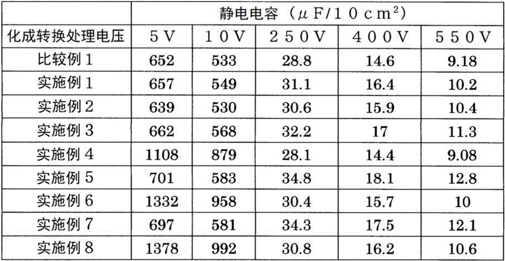
After the electrode material was subjected to chemical conversion treatment in an aqueous solution of boric acid (50g/L) at voltages of 5, 10, 250, 400, and 550V, the electrostatic capacitance was measured in an aqueous solution of ammonium borate (3 g/L). The measured projection area is 10cm2。
< comparative example 1, examples 1 to 8 >
Comparative example 1
Average particle diameter D50An aluminum powder (JISA1080, manufactured by eastern alumina corporation, AHUZ58FN) having a particle size of 3.0 μm was mixed with an acrylic resin for paint binders (manufactured by eastern alumina インキ), and the mixture was dispersed in a solvent (toluene-IPA) to obtain a coating liquid of a solid content. The coating liquid was applied to both surfaces of an aluminum foil substrate (SB material) having a thickness of 20 μm using a comma coater so that the thickness of the coating film after firing was 50 μm, respectively, and the coating film was dried. The aluminum foil was sintered at 615 ℃ for 7 hours in an argon atmosphere to produce an electrode material of comparative example 1. The thickness of the sintered electrode material was about 120 μm.
(examples 1 to 8)
The electrode materials obtained in comparative example 1 were subjected to etching treatment under the following conditions, thereby producing electrode materials of examples 1 to 8.
Example 1
[ chemical etching with acidic solution ]
Etching solution: mixed solution of hydrochloric acid and sulfuric acid (hydrochloric acid concentration: 1 mol/L, sulfuric acid concentration: 3 mol/L, concentration 15%), temperature: 40 ℃ and time: 2min
Example 2
[ chemical etching with alkaline solution ]
Etching solution: caustic soda (concentration 5%), temperature 25 deg.C, time 2min
Example 3
[ DC electrolytic etching ]
Etching solution: hydrochloric acid aqueous solution (hydrochloric acid concentration 15%), temperature 80 ℃, electrolysis: DC30A/50cm2×10sec
Example 4
[ AC electrolytic etching ]
Etching solution: hydrochloric acid aqueous solution (hydrochloric acid concentration 15%), temperature 55 ℃, electrolysis: AC30A/50cm2×10sec
Example 5
[ chemical etching with acidic solution ]
Etching solution: hydrochloric acid water solution (hydrochloric acid concentration 15%), temperature 40 deg.C, and time 2min
After the chemical etching with the acidic solution, the following direct-current electrolytic etching was performed.
[ DC electrolytic etching ]
Etching solution: hydrochloric acid aqueous solution (hydrochloric acid concentration 15%), temperature 80 ℃, electrolysis: DC30A/50cm2×10sec
Example 6
[ chemical etching with acidic solution ]
Etching solution: hydrochloric acid water solution (hydrochloric acid concentration 15%), temperature 40 deg.C, and time 2min
After the chemical etching with the acidic solution, the following alternating current electrolytic etching was performed.
[ AC electrolytic etching ]
Etching solution: hydrochloric acid aqueous solution (hydrochloric acid concentration 15%), temperature 55 ℃, electrolysis: AC30A/50cm2×10sec
Example 7
[ chemical etching with alkaline solution ]
Etching solution: caustic soda (concentration 5%), temperature 25 deg.C, time 2min
After the chemical etching with the alkaline solution, the following direct-current electrolytic etching was performed.
[ DC electrolytic etching ]
Etching solution: hydrochloric acid aqueous solution (hydrochloric acid concentration 15%), temperature 80 ℃, electrolysis: DC30A/50cm2×10sec
Example 8
[ chemical etching with alkaline solution ]
Etching solution: caustic soda (concentration 5%), temperature 25 deg.C, time 2min
After the chemical etching with the alkaline solution, the following alternating current electrolytic etching was performed.
[ AC electrolytic etching ]
Etching solution: hydrochloric acid aqueous solution (hydrochloric acid concentration 15%), temperature 55 ℃, electrolysis: AC30A/50cm2×10sec
The results are shown in Table 1.
[ TABLE 1 ]
< comparative example 2, examples 9 to 16 >
Instead of the average particle diameter D50Aluminum powder of 3.0 μm using average particle diameter D50Electrode materials of comparative example 2 and examples 9 to 16 were prepared in the same manner as in comparative example 1 and examples 1 to 8, respectively, except that the aluminum powder (JISA1080, manufactured by Toyo aluminum Co., Ltd., AHUZ560F) was 9.0 μm, and the electrostatic capacitance of the obtained electrode materials was measured. The results are shown in Table 2.
[ TABLE 2]
< comparative example 3, examples 17 to 24 >
Instead of the average particle diameter D50Aluminum powder of 3.0 μm using average particle diameter D50Electrode materials of comparative examples 3 and 17 to 24 were prepared in the same manner as in comparative examples 1 and 1 to 8 except that an aluminum powder (JISA1080, manufactured by Toyo aluminum Co., Ltd., AHUZ560F) of 9.0 μm was used, and the thickness of the film after firing was 100 μm on both surfaces of the aluminum foil substrate (SB material), and the electrode materials obtained were measuredAnd (4) electrostatic capacitance. The results are shown in Table 3.
[ TABLE 3 ]
< comparative example 4, examples 25 to 32 >
Instead of the average particle diameter D50Aluminum powder of 3.0 μm using average particle diameter D50Except for 30.0 μm aluminum powder, electrode materials of comparative example 4 and examples 25 to 32 were prepared in the same manner as in comparative example 1 and examples 1 to 8, respectively, and the electrostatic capacitance of the obtained electrode materials was measured. The results are shown in Table 4.
[ TABLE 4 ]
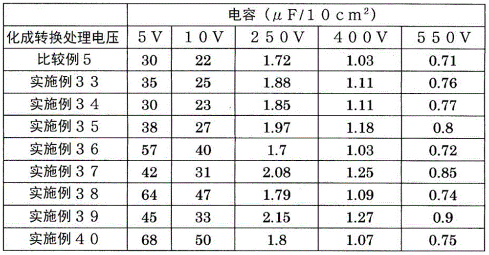
< comparative example 5, examples 33 to 40 >
Instead of the average particle diameter D50Aluminum powder of 3.0 μm using average particle diameter D50Except for 80.0 μm aluminum powder, electrode materials of comparative examples 5 and examples 33 to 40 were prepared in the same manner as in comparative example 1 and examples 1 to 8, respectively, and the electrostatic capacitance of the obtained electrode materials was measured. The results are shown in Table 5.
[ TABLE 5 ]
[ results ]
In comparative example 1 and examples 1 to 8, since the electrode material was produced in comparative example 1 by a production method not including the etching treatment, the electrostatic capacitance was low in all regions from the low voltage region where the chemical conversion treatment voltage was 10V or less to the middle-high voltage region of 250 to 550V.
On the other hand, in examples 1 to 3, since chemical etching with an acidic solution, chemical etching with an alkaline solution, or direct current electrolytic etching was performed, the electrostatic capacitance was improved in a high voltage region of 250 to 550V as compared with comparative example 1. In particular, in the electrode material subjected to the DC electrolytic etching in example 3, the electrostatic capacitance was improved by 10 to 20% in a high voltage region of 250 to 550V.
In example 4, since ac electrolytic etching was performed, the capacitance was improved in a low voltage region where the chemical conversion processing voltage was 10V or less, compared with comparative example 1.
In examples 5 to 8, since the chemical etching with the acidic solution or the chemical etching with the alkaline solution was performed and then the dc electrolytic etching or the ac electrolytic etching was further performed, the electrostatic capacitance was improved in both the low voltage region of 10V or less and the high voltage region of 250 to 550V as compared with comparative example 1.
The above-mentioned tendency is also present between comparative example 2 and examples 9 to 16, between comparative example 3 and examples 17 to 24, between comparative example 4 and examples 25 to 32, and between comparative example 5 and examples 33 to 40. Therefore, according to the production method of the present invention, it is found that the average particle diameter (D) is used even when50) Even in the case of a large powder, the electrostatic capacitance of the electrode material for an aluminum electrolytic capacitor can be increased, and an electrode material for an aluminum electrolytic capacitor exhibiting desired characteristics can be obtained by appropriately and selectively performing etching treatment.