CN104822446B - Improved flow reactor - Google Patents
Improved flow reactor Download PDFInfo
- Publication number
- CN104822446B CN104822446B CN201380063376.0A CN201380063376A CN104822446B CN 104822446 B CN104822446 B CN 104822446B CN 201380063376 A CN201380063376 A CN 201380063376A CN 104822446 B CN104822446 B CN 104822446B
- Authority
- CN
- China
- Prior art keywords
- tubular reactor
- reactor
- flow
- mixing
- reaction
- Prior art date
- Legal status (The legal status is an assumption and is not a legal conclusion. Google has not performed a legal analysis and makes no representation as to the accuracy of the status listed.)
- Active
Links
- 239000000463 material Substances 0.000 claims abstract description 79
- 238000002156 mixing Methods 0.000 claims abstract description 78
- 238000000034 method Methods 0.000 claims abstract description 57
- 230000008569 process Effects 0.000 claims abstract description 50
- 238000006243 chemical reaction Methods 0.000 claims abstract description 39
- 230000003068 static effect Effects 0.000 claims abstract description 22
- 239000012530 fluid Substances 0.000 claims description 37
- 230000008859 change Effects 0.000 claims description 12
- 239000000126 substance Substances 0.000 claims description 6
- 238000012544 monitoring process Methods 0.000 claims 2
- 238000012546 transfer Methods 0.000 description 15
- 239000012071 phase Substances 0.000 description 12
- 238000001816 cooling Methods 0.000 description 10
- 230000007246 mechanism Effects 0.000 description 8
- 239000000203 mixture Substances 0.000 description 8
- 238000005452 bending Methods 0.000 description 7
- 230000002829 reductive effect Effects 0.000 description 7
- 230000002441 reversible effect Effects 0.000 description 7
- 238000010438 heat treatment Methods 0.000 description 6
- 239000007788 liquid Substances 0.000 description 6
- 238000004519 manufacturing process Methods 0.000 description 6
- 230000035484 reaction time Effects 0.000 description 6
- 239000007787 solid Substances 0.000 description 6
- 238000013461 design Methods 0.000 description 5
- 238000000926 separation method Methods 0.000 description 5
- 230000008901 benefit Effects 0.000 description 4
- 230000000694 effects Effects 0.000 description 4
- 239000002002 slurry Substances 0.000 description 4
- 150000001875 compounds Chemical class 0.000 description 3
- 230000008878 coupling Effects 0.000 description 3
- 238000010168 coupling process Methods 0.000 description 3
- 238000005859 coupling reaction Methods 0.000 description 3
- 238000012545 processing Methods 0.000 description 3
- 239000000243 solution Substances 0.000 description 3
- 238000007792 addition Methods 0.000 description 2
- 238000002425 crystallisation Methods 0.000 description 2
- 230000008025 crystallization Effects 0.000 description 2
- 238000009792 diffusion process Methods 0.000 description 2
- 238000000605 extraction Methods 0.000 description 2
- 239000002783 friction material Substances 0.000 description 2
- 230000006870 function Effects 0.000 description 2
- 239000013529 heat transfer fluid Substances 0.000 description 2
- 238000009434 installation Methods 0.000 description 2
- 230000000670 limiting effect Effects 0.000 description 2
- 239000002184 metal Substances 0.000 description 2
- 229910052751 metal Inorganic materials 0.000 description 2
- 239000004033 plastic Substances 0.000 description 2
- 238000006116 polymerization reaction Methods 0.000 description 2
- 238000007789 sealing Methods 0.000 description 2
- 229910000975 Carbon steel Inorganic materials 0.000 description 1
- 230000001133 acceleration Effects 0.000 description 1
- 230000009471 action Effects 0.000 description 1
- 230000004323 axial length Effects 0.000 description 1
- 239000010962 carbon steel Substances 0.000 description 1
- 239000003054 catalyst Substances 0.000 description 1
- 229910010293 ceramic material Inorganic materials 0.000 description 1
- 239000007795 chemical reaction product Substances 0.000 description 1
- 238000004140 cleaning Methods 0.000 description 1
- 230000002301 combined effect Effects 0.000 description 1
- 230000002860 competitive effect Effects 0.000 description 1
- 239000002131 composite material Substances 0.000 description 1
- 239000012141 concentrate Substances 0.000 description 1
- 230000007797 corrosion Effects 0.000 description 1
- 238000005260 corrosion Methods 0.000 description 1
- 239000003085 diluting agent Substances 0.000 description 1
- 238000010790 dilution Methods 0.000 description 1
- 239000012895 dilution Substances 0.000 description 1
- 238000007599 discharging Methods 0.000 description 1
- 239000012847 fine chemical Substances 0.000 description 1
- 238000007667 floating Methods 0.000 description 1
- 235000013305 food Nutrition 0.000 description 1
- 239000011521 glass Substances 0.000 description 1
- 230000005484 gravity Effects 0.000 description 1
- 229910000856 hastalloy Inorganic materials 0.000 description 1
- 229910052500 inorganic mineral Inorganic materials 0.000 description 1
- 239000007791 liquid phase Substances 0.000 description 1
- 238000012423 maintenance Methods 0.000 description 1
- 230000014759 maintenance of location Effects 0.000 description 1
- 238000005259 measurement Methods 0.000 description 1
- 150000002739 metals Chemical class 0.000 description 1
- 239000011707 mineral Substances 0.000 description 1
- 238000012986 modification Methods 0.000 description 1
- 230000004048 modification Effects 0.000 description 1
- 238000006384 oligomerization reaction Methods 0.000 description 1
- 230000003287 optical effect Effects 0.000 description 1
- 239000002245 particle Substances 0.000 description 1
- 238000001556 precipitation Methods 0.000 description 1
- 239000000047 product Substances 0.000 description 1
- 230000009467 reduction Effects 0.000 description 1
- 238000007670 refining Methods 0.000 description 1
- 230000004044 response Effects 0.000 description 1
- 230000000717 retained effect Effects 0.000 description 1
- 230000035939 shock Effects 0.000 description 1
- 239000002904 solvent Substances 0.000 description 1
- 239000010935 stainless steel Substances 0.000 description 1
- 229910001220 stainless steel Inorganic materials 0.000 description 1
- -1 stainless steel Chemical class 0.000 description 1
- 210000005239 tubule Anatomy 0.000 description 1
Images


Classifications
-
- B—PERFORMING OPERATIONS; TRANSPORTING
- B01—PHYSICAL OR CHEMICAL PROCESSES OR APPARATUS IN GENERAL
- B01J—CHEMICAL OR PHYSICAL PROCESSES, e.g. CATALYSIS OR COLLOID CHEMISTRY; THEIR RELEVANT APPARATUS
- B01J19/00—Chemical, physical or physico-chemical processes in general; Their relevant apparatus
- B01J19/28—Moving reactors, e.g. rotary drums
-
- B—PERFORMING OPERATIONS; TRANSPORTING
- B01—PHYSICAL OR CHEMICAL PROCESSES OR APPARATUS IN GENERAL
- B01F—MIXING, e.g. DISSOLVING, EMULSIFYING OR DISPERSING
- B01F25/00—Flow mixers; Mixers for falling materials, e.g. solid particles
- B01F25/40—Static mixers
- B01F25/42—Static mixers in which the mixing is affected by moving the components jointly in changing directions, e.g. in tubes provided with baffles or obstructions
- B01F25/43—Mixing tubes, e.g. wherein the material is moved in a radial or partly reversed direction
- B01F25/431—Straight mixing tubes with baffles or obstructions that do not cause substantial pressure drop; Baffles therefor
- B01F25/4312—Straight mixing tubes with baffles or obstructions that do not cause substantial pressure drop; Baffles therefor having different kinds of baffles, e.g. plates alternating with screens
-
- B—PERFORMING OPERATIONS; TRANSPORTING
- B01—PHYSICAL OR CHEMICAL PROCESSES OR APPARATUS IN GENERAL
- B01F—MIXING, e.g. DISSOLVING, EMULSIFYING OR DISPERSING
- B01F25/00—Flow mixers; Mixers for falling materials, e.g. solid particles
- B01F25/40—Static mixers
- B01F25/42—Static mixers in which the mixing is affected by moving the components jointly in changing directions, e.g. in tubes provided with baffles or obstructions
- B01F25/43—Mixing tubes, e.g. wherein the material is moved in a radial or partly reversed direction
- B01F25/431—Straight mixing tubes with baffles or obstructions that do not cause substantial pressure drop; Baffles therefor
- B01F25/4316—Straight mixing tubes with baffles or obstructions that do not cause substantial pressure drop; Baffles therefor the baffles being flat pieces of material, e.g. intermeshing, fixed to the wall or fixed on a central rod
- B01F25/43161—Straight mixing tubes with baffles or obstructions that do not cause substantial pressure drop; Baffles therefor the baffles being flat pieces of material, e.g. intermeshing, fixed to the wall or fixed on a central rod composed of consecutive sections of flat pieces of material
-
- B—PERFORMING OPERATIONS; TRANSPORTING
- B01—PHYSICAL OR CHEMICAL PROCESSES OR APPARATUS IN GENERAL
- B01F—MIXING, e.g. DISSOLVING, EMULSIFYING OR DISPERSING
- B01F25/00—Flow mixers; Mixers for falling materials, e.g. solid particles
- B01F25/40—Static mixers
- B01F25/42—Static mixers in which the mixing is affected by moving the components jointly in changing directions, e.g. in tubes provided with baffles or obstructions
- B01F25/43—Mixing tubes, e.g. wherein the material is moved in a radial or partly reversed direction
- B01F25/431—Straight mixing tubes with baffles or obstructions that do not cause substantial pressure drop; Baffles therefor
- B01F25/43197—Straight mixing tubes with baffles or obstructions that do not cause substantial pressure drop; Baffles therefor characterised by the mounting of the baffles or obstructions
- B01F25/431972—Mounted on an axial support member, e.g. a rod or bar
-
- B—PERFORMING OPERATIONS; TRANSPORTING
- B01—PHYSICAL OR CHEMICAL PROCESSES OR APPARATUS IN GENERAL
- B01F—MIXING, e.g. DISSOLVING, EMULSIFYING OR DISPERSING
- B01F27/00—Mixers with rotary stirring devices in fixed receptacles; Kneaders
- B01F27/05—Stirrers
- B01F27/07—Stirrers characterised by their mounting on the shaft
- B01F27/071—Fixing of the stirrer to the shaft
-
- B—PERFORMING OPERATIONS; TRANSPORTING
- B01—PHYSICAL OR CHEMICAL PROCESSES OR APPARATUS IN GENERAL
- B01F—MIXING, e.g. DISSOLVING, EMULSIFYING OR DISPERSING
- B01F27/00—Mixers with rotary stirring devices in fixed receptacles; Kneaders
- B01F27/05—Stirrers
- B01F27/07—Stirrers characterised by their mounting on the shaft
- B01F27/072—Stirrers characterised by their mounting on the shaft characterised by the disposition of the stirrers with respect to the rotating axis
- B01F27/0721—Stirrers characterised by their mounting on the shaft characterised by the disposition of the stirrers with respect to the rotating axis parallel with respect to the rotating axis
-
- B—PERFORMING OPERATIONS; TRANSPORTING
- B01—PHYSICAL OR CHEMICAL PROCESSES OR APPARATUS IN GENERAL
- B01F—MIXING, e.g. DISSOLVING, EMULSIFYING OR DISPERSING
- B01F27/00—Mixers with rotary stirring devices in fixed receptacles; Kneaders
- B01F27/05—Stirrers
- B01F27/07—Stirrers characterised by their mounting on the shaft
- B01F27/072—Stirrers characterised by their mounting on the shaft characterised by the disposition of the stirrers with respect to the rotating axis
- B01F27/0724—Stirrers characterised by their mounting on the shaft characterised by the disposition of the stirrers with respect to the rotating axis directly mounted on the rotating axis
-
- B—PERFORMING OPERATIONS; TRANSPORTING
- B01—PHYSICAL OR CHEMICAL PROCESSES OR APPARATUS IN GENERAL
- B01F—MIXING, e.g. DISSOLVING, EMULSIFYING OR DISPERSING
- B01F27/00—Mixers with rotary stirring devices in fixed receptacles; Kneaders
- B01F27/05—Stirrers
- B01F27/11—Stirrers characterised by the configuration of the stirrers
- B01F27/112—Stirrers characterised by the configuration of the stirrers with arms, paddles, vanes or blades
- B01F27/1125—Stirrers characterised by the configuration of the stirrers with arms, paddles, vanes or blades with vanes or blades extending parallel or oblique to the stirrer axis
-
- B—PERFORMING OPERATIONS; TRANSPORTING
- B01—PHYSICAL OR CHEMICAL PROCESSES OR APPARATUS IN GENERAL
- B01F—MIXING, e.g. DISSOLVING, EMULSIFYING OR DISPERSING
- B01F27/00—Mixers with rotary stirring devices in fixed receptacles; Kneaders
- B01F27/05—Stirrers
- B01F27/11—Stirrers characterised by the configuration of the stirrers
- B01F27/115—Stirrers characterised by the configuration of the stirrers comprising discs or disc-like elements essentially perpendicular to the stirrer shaft axis
- B01F27/1151—Stirrers characterised by the configuration of the stirrers comprising discs or disc-like elements essentially perpendicular to the stirrer shaft axis with holes on the surface
-
- B—PERFORMING OPERATIONS; TRANSPORTING
- B01—PHYSICAL OR CHEMICAL PROCESSES OR APPARATUS IN GENERAL
- B01F—MIXING, e.g. DISSOLVING, EMULSIFYING OR DISPERSING
- B01F27/00—Mixers with rotary stirring devices in fixed receptacles; Kneaders
- B01F27/05—Stirrers
- B01F27/11—Stirrers characterised by the configuration of the stirrers
- B01F27/19—Stirrers with two or more mixing elements mounted in sequence on the same axis
- B01F27/191—Stirrers with two or more mixing elements mounted in sequence on the same axis with similar elements
-
- B—PERFORMING OPERATIONS; TRANSPORTING
- B01—PHYSICAL OR CHEMICAL PROCESSES OR APPARATUS IN GENERAL
- B01F—MIXING, e.g. DISSOLVING, EMULSIFYING OR DISPERSING
- B01F27/00—Mixers with rotary stirring devices in fixed receptacles; Kneaders
- B01F27/05—Stirrers
- B01F27/11—Stirrers characterised by the configuration of the stirrers
- B01F27/19—Stirrers with two or more mixing elements mounted in sequence on the same axis
- B01F27/192—Stirrers with two or more mixing elements mounted in sequence on the same axis with dissimilar elements
-
- B—PERFORMING OPERATIONS; TRANSPORTING
- B01—PHYSICAL OR CHEMICAL PROCESSES OR APPARATUS IN GENERAL
- B01F—MIXING, e.g. DISSOLVING, EMULSIFYING OR DISPERSING
- B01F27/00—Mixers with rotary stirring devices in fixed receptacles; Kneaders
- B01F27/55—Mixers with rotary stirring devices in fixed receptacles; Kneaders with stirrers driven by the moving material
-
- B—PERFORMING OPERATIONS; TRANSPORTING
- B01—PHYSICAL OR CHEMICAL PROCESSES OR APPARATUS IN GENERAL
- B01F—MIXING, e.g. DISSOLVING, EMULSIFYING OR DISPERSING
- B01F31/00—Mixers with shaking, oscillating, or vibrating mechanisms
- B01F31/10—Mixers with shaking, oscillating, or vibrating mechanisms with a mixing receptacle rotating alternately in opposite directions
-
- B—PERFORMING OPERATIONS; TRANSPORTING
- B01—PHYSICAL OR CHEMICAL PROCESSES OR APPARATUS IN GENERAL
- B01F—MIXING, e.g. DISSOLVING, EMULSIFYING OR DISPERSING
- B01F31/00—Mixers with shaking, oscillating, or vibrating mechanisms
- B01F31/44—Mixers with shaking, oscillating, or vibrating mechanisms with stirrers performing an oscillatory, vibratory or shaking movement
- B01F31/445—Mixers with shaking, oscillating, or vibrating mechanisms with stirrers performing an oscillatory, vibratory or shaking movement performing an oscillatory movement about an axis
-
- B—PERFORMING OPERATIONS; TRANSPORTING
- B01—PHYSICAL OR CHEMICAL PROCESSES OR APPARATUS IN GENERAL
- B01F—MIXING, e.g. DISSOLVING, EMULSIFYING OR DISPERSING
- B01F31/00—Mixers with shaking, oscillating, or vibrating mechanisms
- B01F31/57—Mixers with shaking, oscillating, or vibrating mechanisms for material continuously moving therethrough
-
- B—PERFORMING OPERATIONS; TRANSPORTING
- B01—PHYSICAL OR CHEMICAL PROCESSES OR APPARATUS IN GENERAL
- B01J—CHEMICAL OR PHYSICAL PROCESSES, e.g. CATALYSIS OR COLLOID CHEMISTRY; THEIR RELEVANT APPARATUS
- B01J19/00—Chemical, physical or physico-chemical processes in general; Their relevant apparatus
- B01J19/0053—Details of the reactor
- B01J19/006—Baffles
-
- B—PERFORMING OPERATIONS; TRANSPORTING
- B01—PHYSICAL OR CHEMICAL PROCESSES OR APPARATUS IN GENERAL
- B01J—CHEMICAL OR PHYSICAL PROCESSES, e.g. CATALYSIS OR COLLOID CHEMISTRY; THEIR RELEVANT APPARATUS
- B01J19/00—Chemical, physical or physico-chemical processes in general; Their relevant apparatus
- B01J19/0053—Details of the reactor
- B01J19/0066—Stirrers
-
- B—PERFORMING OPERATIONS; TRANSPORTING
- B01—PHYSICAL OR CHEMICAL PROCESSES OR APPARATUS IN GENERAL
- B01F—MIXING, e.g. DISSOLVING, EMULSIFYING OR DISPERSING
- B01F2215/00—Auxiliary or complementary information in relation with mixing
- B01F2215/04—Technical information in relation with mixing
- B01F2215/0413—Numerical information
- B01F2215/0418—Geometrical information
- B01F2215/0422—Numerical values of angles
-
- B—PERFORMING OPERATIONS; TRANSPORTING
- B01—PHYSICAL OR CHEMICAL PROCESSES OR APPARATUS IN GENERAL
- B01F—MIXING, e.g. DISSOLVING, EMULSIFYING OR DISPERSING
- B01F2215/00—Auxiliary or complementary information in relation with mixing
- B01F2215/04—Technical information in relation with mixing
- B01F2215/0413—Numerical information
- B01F2215/0436—Operational information
- B01F2215/0481—Numerical speed values
-
- B—PERFORMING OPERATIONS; TRANSPORTING
- B01—PHYSICAL OR CHEMICAL PROCESSES OR APPARATUS IN GENERAL
- B01J—CHEMICAL OR PHYSICAL PROCESSES, e.g. CATALYSIS OR COLLOID CHEMISTRY; THEIR RELEVANT APPARATUS
- B01J2219/00—Chemical, physical or physico-chemical processes in general; Their relevant apparatus
- B01J2219/00761—Details of the reactor
- B01J2219/00763—Baffles
-
- B—PERFORMING OPERATIONS; TRANSPORTING
- B01—PHYSICAL OR CHEMICAL PROCESSES OR APPARATUS IN GENERAL
- B01J—CHEMICAL OR PHYSICAL PROCESSES, e.g. CATALYSIS OR COLLOID CHEMISTRY; THEIR RELEVANT APPARATUS
- B01J2219/00—Chemical, physical or physico-chemical processes in general; Their relevant apparatus
- B01J2219/19—Details relating to the geometry of the reactor
- B01J2219/194—Details relating to the geometry of the reactor round
- B01J2219/1941—Details relating to the geometry of the reactor round circular or disk-shaped
- B01J2219/1943—Details relating to the geometry of the reactor round circular or disk-shaped cylindrical
Landscapes
- Chemical & Material Sciences (AREA)
- Chemical Kinetics & Catalysis (AREA)
- Dispersion Chemistry (AREA)
- Organic Chemistry (AREA)
- Physical Or Chemical Processes And Apparatus (AREA)
- Mixers Of The Rotary Stirring Type (AREA)
- Mixers With Rotating Receptacles And Mixers With Vibration Mechanisms (AREA)
- Accessories For Mixers (AREA)
Abstract
A tubular reactor is provided with means by which the tube can be rotated through reciprocating arcs about its longitudinal axis to provide a combination of radial mixing and plug flow to enable reactions, wherein the process material is continuously passed through the tubular reactor which is operated at predetermined reaction conditions. Static and/or dynamic mixers or stirrers may be provided inside the tubular reactor.
Description
The present invention relates to a method and apparatus for mixing fluids in a pipe, particularly for applications requiring good plug flow or good mixing, especially when both are required. The method and apparatus can be used to deliver heterogeneous fluid mixtures (e.g., slurries) that require constant mixing, but preferably for applications where both good mixing and good plug flow are desired. The methods and apparatus of the present invention facilitate a wide range of processes, including physical, biological, and/or chemical changes. Mixing, physical reactions (e.g., crystallization), gas phase, slurry phase, mixed phase reactions, and reactions in the liquid phase. The range of applications includes, but is not limited to: for the whole range of manufacturing processes, pharmaceutical, biological, fine chemical, petrochemical and refining processes, polymerization and mineral processing of food products.
Flow reactors are primarily steady state systems in which the process material undergoes a physical, chemical or biological change as it passes continuously through the reactor. For a given treatment cycle, only a portion of the treatment material remains in the reactor at any time (unlike a batch reactor in which all of the treatment material for the treatment cycle is present at some point in time). An advantage of flow reactors over batch reactors is the reduced physical size, which helps to better mix the process fluid and improve heat transfer (by reducing the size) between the process fluid and the reactor body. The commercial advantages of flow reactors over batch reactors for industrial processes depend on the application, but include to varying degrees reduced capital costs, higher yields, improved product purity, reduced solvent use, improved safety, and lower energy requirements, thus reducing costs. These advantages are well documented in the literature.
The difference between a conveyor for moving the process material and a flow reactor is that in a conveyor the material is transferred from one point to another, whereas in a flow reactor the properties of the process material undergo a physical, biological or chemical change as it passes through the reactor. Thus, the properties of the process material change as the reaction proceeds along the reactor. Plug flow means that the process material is running through and out of the reactor in the same chronological order as it entered. Plug flow is therefore important to control reaction time and optimize separation of unreacted and reacted materials. Failure to obtain good plug flow can seriously impair the performance of the reactor, since otherwise the reaction time cannot be controlled, backmixing of the process materials can lead to undesired reactions and to a reduction in the reaction rate (due to dilution effects in the case of the n-th order reaction). Good mixing (more preferably good radial mixing) is also required to ensure efficient mixing, uniformity of the process material within the reactor, and good heat transfer.
The invention provides a tubular reactor provided with means by which the tube can be rotated about its longitudinal axis through a reciprocating circular arc.
In a further embodiment, the invention provides a reaction wherein the process material is continuously passed through a tubular reactor operating at predetermined reaction conditions, wherein the tubular reactor is rotated through a reciprocating circular arc about the longitudinal axis of the tube as the process material passes therethrough.
The following terms have the following meanings.
Flow reactor-this is a channel or series of stages through which the treatment material flows in series and in which a physical, chemical or biological change occurs as the treatment material passes through it.
The process material is the material flowing through the reactor. This may include reactive and non-reactive materials (e.g., diluents or catalysts). The composition of the process material will vary along the reactor as the material changes or reacts to form the desired reaction product. The process material may be a liquid, gas, vapor, critical fluid, or any other material capable of flowing. It may also be a mixture of these materials, and the treatment material may also contain solid particles.
Tubular flow reactor-a flow reactor in which the total length of the channels in the flow direction is 3 times larger, more preferably 5 times larger, and still more preferably 10 times larger than the diameter of the channels. Tubular flow reactors may be composed of a single tube or multiple tubes.
Plug flow-a well-known term, is an ordered flow pattern through a reactor in which minimal back mixing occurs and substantially all of the flow elements have substantially the same residence time in the reactor. Ideal (100%) plug flow cannot be achieved in practice due to the effects of diffusion and fluid mixing. In this context, plug flow means that residence time control corresponds to at least 5 tanks in series per reactor tube (multiple tubes may be used for the reactor), more preferably 10 tubes in series or more. In many cases, the plug flow quality required will vary in response to the change in reaction rate produced in the nth reaction. In such applications, different diameter tubes along the length of the channel can be used, taking into account different plug flow requirements. This means that small diameter tubes are used when higher plug flow quality is required (this gives higher velocity and therefore better plug flow).
Mixing-all fluids are mixed to some extent by molecular diffusion. Mixing, as used herein, refers to the differential movement of larger (bulk) fluid elements to achieve mixing uniformity, shear, heat transfer, and plug flow under desired conditions. The mixing conditions may be turbulent or laminar.
Axial mixing-this is mixing in an axial plane (typically along a tube) in the direction of the net flow direction of the process material.
Radial mixing-this is mixing in a radial plane (typically transverse to the tube) that is 90 degrees to the net flow direction of the process material. The preferred mixing action is to have a high degree of radial mixing and a low degree of axial mixing.
Static mixer-this is a mixing element that remains stationary relative to the reactor body.
Dynamic mixer-this is a mixing element that moves relative to the reactor body.
Deflector-this is a plate across the diameter of the flow channel, which plate has holes to allow the passage of fluid in the axial direction along the tube.
The treatment material may have a high solids concentration, but the preferred concentration of solids in the treatment material is less than 50% by volume, more preferably less than 25% by volume. Changes due to reactions of the treatment material include, but are not limited to, precipitation, crystallization, chemical reactions, biological reactions, oligomerization, polymerization, and extraction.
The mixing can be characterized in a variety of ways, but in this context mixing means thorough mixing. For homogeneous fluids, mixing means a mixing time of less than 10 seconds, more preferably less than 5 seconds, and still more preferably less than 1 second. In some applications (e.g., very slow reactions), longer mixing times may also be acceptable. For heterogeneous materials, thorough mixing will be equivalent to or better than a 1 liter stirred vessel with inclined turbine blades rotating at 100rpm, more preferably at 200rpm, and still more preferably at 400 rpm. In some applications, the mixing may not be comparable to these.
The reactor may also have a system for adding or removing heat, such as a temperature control jacket, as desired. When the reactor is provided with a stirrer shaft, the shaft may comprise a cooling system. Static and dynamic mixers may also contain cooling systems. A preferred temperature control system includes a temperature sensor, a controller, and a control element (e.g., a valve) for varying the temperature or flow rate of the heat transfer fluid in order to control the temperature of the process material. In the case of electrical heating or cooling, the control element will vary the electrical power applied. The temperature sensor may be arranged in the flow of heat transfer fluid or, more preferably, in the flow of process material. Multiple temperature control systems may also be used for multiple heating or cooling stages along a tube or separate tubes but connected within the same system to address different temperature control requirements at different stages of the reaction.
The flow reactor may also have on-axis analytical devices, such as optical analyzers, pH sensors or calorimeters, to monitor and/or control the operation of the reactor. The analytical device may be a component of a control system that includes an analytical sensor, a controller, and a control element that controls one or more variables. The preferred location for the individual analyzers is at the point where the process material is discharged from the reactor, although other locations may be used. The controlled variable may be one or more of the flow rate of the feed material, the system pressure, the system temperature, or any other parameter that affects the performance of the reactor. More complex control systems can also use multiple analyzers that control one or more reactor components, and can be arranged in different locations within the reactor.
The flow reactor may be provided with one or more internal baffles. The function of the deflector is to reduce back mixing (and hence improve plug flow), but can also be used to support the agitator shaft, thus preventing excessive bending of the shaft.
The invention described herein provides an efficient and economical solution to the four key requirements of a flow reactor.
Volumetric capacity-sufficient volumetric capacity is required to ensure that the reaction is complete for a given production. By producing efficient mixing independent of the velocity of the fluid through the reactor (as is the case with conventional static mixer flow reactors), the present invention provides lower cost volumetric capacity per unit volume (as compared to long tubules) and lower pressure drop (because short and larger diameter tubes can be used without sacrificing mixing performance).
Plug flow-plug flow establishment provides a means for controlling reaction time and optimizing the separation of reacted and unreacted process materials. For any process, when a good plug flow is used, the flow reactor will be small because the reacted material will be discharged in a timely manner and not retained. For many processes (e.g., the nth competition or continuous reaction), good plug flow is required for maximizing yield, selectivity, and purity per unit volume. The present invention provides a method for producing a high ratio of radial to axial mixing that is desirable for good plug flow. The present invention provides a means for obtaining plug flow at lower velocities and pressure drops (than required in simple tubes or static mixers).
Advantages of mix-good mixing include: fast mixing times, good heat transfer coefficients, good mass transfer between heterogeneous fluids, good slurry transfer, and good plug flow promotion (by eliminating poorly mixed fluid regions running at different axial velocities). These requirements will vary depending on the treatment application. The present invention provides for efficient mixing in a wide range of applications and is independent of the velocity of the fluid through the reactor.
Heat transfer-effective heat transfer is required to add or remove heat in order to maintain the process material at the desired temperature. The present invention provides a means of assembling an external heating/cooling jacket and internal cooling tubes to control the process temperature. Such a design accommodates a wide range of tube diameters, and by selecting different tube diameters, different ratios of heat transfer area to working volume can be achieved.
Temperature control-temperature control means applying heating or cooling in order to change or maintain the temperature of the process material at a desired value. The preferable meaning of the temperature control usable in the present invention is reaction temperature control. This means that the process temperature is maintained or changed to the desired value, wherein the reaction is exothermic or endothermic.
Two broad categories of flow reactors are commonly used. Static flow reactors rely on the movement of fluids through the reactor to produce mixing (either by turbulence or using splitting/bending/folding of baffles or static mixing elements). A common dynamic flow reactor uses mixer blades mounted on a rotating shaft. Such systems are expensive to build because they require mechanical seals or magnetic couplings. They also suffer from the practical problem of the shaft bending in longer tubes. In practice, such systems are usually built as stirred tanks in series. This adds cost and complexity because multiple stages are required to achieve performance comparable to good plug flow. Patents WO2008/068019 and WO2011/124365 describe dynamic mixing processes in a flow reactor, in which the body of the reactor undergoes a rocking that generates a movement of an internal stirrer of different density than the process fluid. The internal agitators are loose elements or they may be tethered to the vessel. As the liquid-filled tube moves laterally (as described in the prior art), the position of the fluid relative to the tube remains stationary. In these cases, mixing only occurs when more than one density of material is present.
According to the invention, the flow reactor is rotated through a reverse arc around the long axis of the tube. Under these conditions, the inertia of the fluid will oppose the rotation, thereby creating differential motion between the fluid and the inner surface of the reactor body and any stationary elements inside it. Unlike the aforementioned prior art, this technique produces differential motion of the fluids (and thus mixing) even when the reactor contents are of uniform density. A further optional feature of the present invention is that a rotary agitator (dynamic agitator) can also be used, which is mounted on one or more shafts within the fluid reactor. They also rely on the rotational movement of the reactor body to produce independent movement, thereby increasing mixing.
The present invention shows, but is not limited to, the accompanying drawings in which a tubular reactor is provided with means by which the tube can be rotated through reciprocating arcs about the longitudinal axis of the tube to provide radial mixing in combination with plug flow to enable reactions in which the process material is continuously passed through the tubular reactor which is operated at predetermined reaction conditions.
Static and/or dynamic mixers may be provided within the tubular reactor.
Figure 1 shows a conventional flow reactor.
Figure 2 shows a detail of the dynamic mixer and shaft.
Fig. 3 shows details of the static mixer and shaft.
Figure 4 shows the reactor mounting and drive unit.
Fig. 5 shows the stirrer stopper.
Fig. 6 shows a complex mixer (complex mixer) having simple mixers combined together.
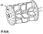
Figure 7 shows the baffle being disposed within the reactor.
Figure 8 shows the flow path of the treatment material across the agitator.
A typical flow reactor is shown in figure 1 and comprises a channel 1, which channel 1 will typically be a circular tube, with a support flange at each end 2. The sealing flange 3 is bolted to the support flange to form a sealing system. The tube will be made of a material that provides sufficient mechanical strength to resist twisting or damage when operated under ambient, elevated pressure or vacuum. The tubes may be made from a variety of metals, such as stainless steel, hastelloy, carbon steel, and the like. Alternatively, it may be made of glass, ceramic material or even plastic. When a combination of high mechanical strength and good corrosion resistance is required, the reactor body may be manufactured in one material and coated or lined with a different material. The supply pipe 4 is shown on one end flange and the discharge pipe 5 is shown on the opposite flange. A plurality of supply and discharge tubes may be used, some of which may be arranged at a midpoint along the tube. Cooling jacket 6 is shown for adding or removing heat. The heat transfer supply pipe 7 is shown at one end of the jacket and the hot fluid discharge pipe 8 is shown at the other end of the jacket. The temperature control system has been described above. Other forms of heating or cooling may be applied to some systems, such as electrical heating elements or Peltier elements. The foregoing description is for the purpose of illustration, and the structure is capable of many variations and modifications.
FIG. 2 shows an exploded detail view of the dynamic mixer, shaft and shaft mounting collar. The stirrer 9 has a central boss 10, the boss 10 having a circular hole in the centre. A plurality of mixing blades 11 are mounted on the boss. The blades may be simple paddles, as shown, they may also be pitched turbines, multiple thin blades, wires, nets or any other shape. The blade(s) 12 have a relatively large mass. In the figures, the added mass is achieved by making the blades physically larger. Alternatively or additionally, the blade may be the same size as the other blades, but made of a more dense material. The agitator is mounted on the shaft 13 by a loose fit. The internal bore of the stirrer shaft and boss should have a smooth low friction surface. O-rings or soft liners may be used to protect the moving surface when the process material contains abrasive solids. The agitator shaft 13 has flat surfaces on the periphery to prevent rotation of the shaft on the shaft support collar 14. Other shaft shapes or alternative methods (e.g., locking nuts) may be used to hold the shaft in a fixed position. Shaft support collars are mounted at each end of the reactor body to retain the stirrer shafts. The shaft support collar may form part of the end flange of the reactor or be mounted on a separate frame or plate at the end of the tube. The preferred location of the stirrer shaft within the reactor is along the central axis. However, for some applications the agitator shaft may not be centrally mounted, in other cases two or more agitator shafts may be used.
FIG. 3 shows an exploded detail view of the static mixer, shaft and shaft mount. The stirrer 15 is fixed to the shaft and, in this example, a flat on the radius of the shaft is used in order to prevent the shaft from rotating. Other methods may be used to secure the agitator to the shaft.
Static and dynamic agitators may be rigid or flexible. The flexible stirrer will give a greater tip travel when the direction of rotation of the stirrer shaft is changed. This gives improved mixing performance and these stirrers may be weighted at the tip in order to increase the bending and mixing effect.
Figure 4 shows the reactor body. It is shown as a tube 16 mounted on a bearing 17, which bearing 17 allows the body of the reactor to rotate. The bearings that allow the reactor to rotate are shown encircling the reactor body but may alternatively be mounted in a rotating bracket or shaft projecting from the reactor body or end. Alternatively (for bearings) rubber gaskets, springs, low friction sleeves or other flexible means may be used to make the reactor body rotatable. The preferred axis of rotation is the central axis of the reactor tube. Alternatively, however, the axis of rotation may be eccentric, for example on a wobble arm. Also shown is a drive mechanism 18, which drive mechanism 18 rotates the reactor on the mount in a reciprocating arc. The driving mechanism may also be assisted by a recoil spring, a pneumatic piston or other means (one element mounted on the stationary object and the other element mounted on the rotary reactor) in order to save energy and help reverse the arc of rotation at the end of its stroke. The drive mechanism shown is a pneumatic or hydraulic piston. Alternative drive mechanisms such as gears, cogs, motors, electromagnetic devices, etc. may also be used. The drive mechanism rotates the reactor through a reciprocating arc (clockwise followed by counter-clockwise, or vice versa). The maximum rotation angle is 360 °. The angle of rotation will vary depending on the application, however, a preferred angle of rotation is between 1 ° and 90 °. The angle of rotation of the reactor body operating under turbulent conditions should be large enough to produce turbulence throughout the reactor volume, which will depend on a number of factors. The angle of rotation of the reactor body under laminar flow conditions should be such that the maximum volume of the tube space is swept by the agitator blades. In this case, the preferred minimum number of blades is 360/n, where n is the number of mixing blades used. The value 360 can be reduced due to the thickness of the blade. More preferably the arc of rotation is less than 45. The rotational speed will vary depending on the application and the angle of rotation and will vary from less than 1 revolution per minute to more than 10 cycles per second.
Mixing by static mixer-although simple tubes are used, static mixing elements as shown in figure 3 are preferred because they are used to produce mixing across the diameter of the tube. The combined effect of the differential motion between the stationary elements of the reactor and the fluid will produce mixing when the reactor body rotates in a reverse circular arc.
Mixing by means of a dynamic mixer-a more preferred solution is to use a dynamic mixing element as shown in figure 2. The mixing elements as shown are unbalanced and free to rotate on the shaft. As the reactor body rotates, they will move at different speeds and phases with respect to the fluid and the fixed agitator. The motion of the dynamic mixer (in terms of velocity and radius of the arc) will vary depending on the characteristics of the process material, the design of the rotating mixer, and the rotational speed and angle of the reactor body. A stopper can be used between the stirrer and a fixed point on the stirrer shaft, as shown in fig. 5. Fixed stop 19 is shown on the static mixer. The fixed stops may also be arranged on the shaft or other parts of the main reactor body. A kinematic stop 20 is shown on the dynamic mixer. By thus using the stopper, the degree of operation of the agitator can be restricted, and the acceleration can also be increased.
The rotation of the dynamic mixer can be through a small circular arc, in which case a larger number of mixer blades is desired in order to ensure a sufficient volume sweep through the reactor space. When turbulent conditions can be achieved, a reduced swept volume can be tolerated as long as the turbulent flow extends to the entire working volume. In some applications, the dynamic mixer will move through an arc of a circle, in other cases the dynamic mixer will rotate continuously in one direction. This can be achieved by adjusting the shock conditions so as to produce a continuous rotation. Continuous rotation can also be facilitated by designing the blade shape so that drag resistance is greater in one rotational direction than the other.
An alternative to the above-described arrangement is to have the dynamic mixer 9 fixed to the shaft and having a freely rotating shaft. In this case, the shaft support collar is circular in inner diameter, allowing the shaft to rotate freely.
In other cases, particularly for viscous fluids, a ratchet mechanism or the like can be used that causes the dynamic mixer to rotate in only one direction. Ratchet mechanisms (or stops) are formed between the locking point (fixed with respect to the reactor body) and the rotating mixer, respectively. In some examples, the dynamic mixers can be arranged such that different mixers (typically adjacent mixers) move in opposite rotational directions. In this case, the continuous rotary agitator can be balanced or unbalanced.
Mixing by means of dynamic and static mixers-for high mixing performance, a more preferred option is to use a combination of static and dynamic mixers. The functional design of these will vary depending on the application, as described in the examples below.
For some mixing applications, a high degree of mixing is required. This will typically be used for processes that require fast mixing times, such as competitive reactions. It will also be used when there is more than one phase (no mixing of liquids, gas/liquid mixtures and solid/liquid mixtures is possible). By having adjacent stirrers running at different speeds and/or in different directions, better mixing will be achieved.
When handling viscous fluids or where good plug flow is required, it is preferable to use a compound mixer with a large surface area and good voidage. This should be a composite structure to enable the fluid to flow through the mixer while breaking up at multiple points. The radial mixing distance of the compound mixer will be small for some applications, which may result in composition and temperature gradients across the diameter. This can be solved by using different types of mixers. Fig. 6 shows a complex mixer 21. Between the compound mixers are simple mixers 22. Simple mixers produce mixing over a larger diameter of the tube, thus redistributing the process material across the diameter. A simple mixer will produce a higher degree of back mixing and it is therefore desirable that the axial length of the tube occupied by the simple mixer element 21 is as short as possible. Alternatively, the location of the holes in the baffle can be used to redistribute the fluid flow between the mixers. To this end, the holes in the baffle may be concentrated at the periphery of the baffle, at the inner diameter of the baffle working surface, or at an intermediate point. The preferred location is at or slightly off the midpoint between the perimeter of the baffle and the inner diameter of the baffle working surface.
When processing multiphase mixtures of different densities in horizontal or near horizontal tubes, there is a tendency for denser phase material to concentrate in the lower half of the tube. In such applications, the reactor as described herein is capable of performing two functions. Dynamic mixers promote good mixing, but can also redistribute the lighter and dense phases in a vertical plane by rocking in a larger arc (compared to reactor rotation) or by continuous rotation. This will cause the denser material to rise and push the lighter material down. By this will increase the phase contact to give a faster reaction.
The diameter of the mixer can range from 10% of the reactor tube diameter to the full diameter depending on the application. For simple blades (such as the blade 15 shown in fig. 3), the preferred diameter is between 40% and 70% of the tube diameter. These are preferably for low viscosity fluids where the impeller is capable of dynamic mixing or for redistribution in the radial plane, as shown at 22 in figure 6. The complex mixer 21 or disk blades shown in fig. 6 are preferably the full diameter of the reactor tube with sufficient clearance for rotation.
The agitator shaft should be strong enough to carry the load of the agitator, ideally being made of a low friction material when a dynamic agitator is used. The inner surface of the dynamic mixer should also be a low friction material. They may also be of a softer material than the shaft (or vice versa) to enable replacement of wear parts.
The range of mixer shapes and sizes that can be used includes cylindrical mixers, balanced or unbalanced. When higher shear per unit volume or higher heat transfer area is required, a cylindrical mixer is used. By using a cylindrical body, the internal tube volume can be reduced to give a higher area to volume ratio, where the high shear required is provided by the narrow space between the stirrer and the inner wall of the tube.
The baffles 23 in figure 7 are used to prevent back mixing. These are perforated plates mounted on the mixer shaft, limiting the flow area so that the process material can only travel in one direction across the baffle. In addition or as an alternative to the holes in the baffles, notches can be used at the periphery and at the top or bottom in order to prevent lighter or heavier material, respectively, from accumulating between the baffles. The baffles may be of different diameters but typically the largest diameter allows them to slide into the tube. The deflector can also be used to support the shaft and prevent excessive bending, where the bending forces are high due to the stirrer. This allows the use of a thinner stirrer shaft (than would be required without the supporting baffles). Different arrangements of baffles and mixers can be used. Figure 7 shows two baffles separated by three mixers, two dynamic and one static. When a simple mixer is used, it is preferred to use 5 or more baffles per reactor tube (there may be multiple tubes in the reactor system), more preferably 10 or more baffles per tube.
Inlet and outlet connections for feeding and discharging process materials will be installed on the tubes at the maximum separation distance for orderly flow, thus making full use of the length of the reactor tubes. The connecting member is fitted to the end plate. When it is desired to access the end plates without disengaging the supply and discharge pipes, the supply and discharge connections are fitted on the walls of the pipes at a minimum distance from the respective end plates. For processes that require multiple additions (e.g., gas/liquid reactions or reactions that exceed the cooling capacity of the reactor), multiple addition points may be assembled along the length of the tube.
The reactor tubes may be mounted horizontally, vertically or obliquely. Tilting is preferred (upward tilting for handling floating material, downward tilting for sinking material) when free drainage is required or to assist the movement of lighter or heavier material along the reactor tube (where there are two phases). When the treatment material has two or more phases of different densities, horizontal or near horizontal tubes are preferred. The reactor tube may be split in an axial plane, but the preferred arrangement is a solid tube.
The length of the reactor tube will vary as desired and can range from 50mm or less to 10 meters or more, but more preferably from 0.5 meters to 3 meters. The shorter tube provides better access for inserting and removing the mixer assembly. When the length of the tube exceeds 3 meters (more preferably exceeds 2 meters), it is preferred to use a plurality of tubes connected together (preferably by flexible connections).
The diameter of the reactor tube varies depending on the application and can vary from less than 1 mm to more than 2 meters. For fast and exothermic reactions (typically reaction times of less than 1 minute), tubes with diameters in the range of 5 mm to 50mm are preferred. The cost per unit volume of the reactor is lower in the case of larger diameter tubes, so when possible, the largest diameter tube is desired. Larger diameter tubes from 50mm to 500 mm are preferred when the reaction time is greater than 1 minute and is not limited by heat transfer requirements. Given the varying reaction rates, a preferred scheme for multiple uses would be to use multiple tubes connected in series, each tube being of the same or different diameter to suit the varying reaction rates.
The reactor is capable of operating over a wide range of pressures and temperatures with the correct material structure and material thickness selected. By not having a moving joint (e.g., a mechanical seal), it will help contain the treatment material.
The system may be used for unidirectional flow or reverse flow. In reverse flow, the two fluids are supplied at different ends of the reactor tube and are each discharged at the opposite respective end. Such methods can be used for certain types of reactions as well as extractions. For such a working process, the counter-flowing fluids must be substantially insoluble and of different densities from each other. The reverse flow system may have unmixed separation zones at each end of the reactor and intermediate separation zones at multiple stages along the length of the reactor.
Flow reactors require supply and discharge pipes in order to transfer fluids from stationary objects (e.g. tanks and pumps) to a rotating reactor body. These tubes must be sufficiently flexible to absorb the rotational movement of the reactor body. When the movement is small, a rigid connection tube having a sufficient length and bending portion can be used so as to absorb the stress of the movement. When the range of motion is large, a rigid tube with a longer radius bend can be used, or a flexible tube, such as a plastic tube or a corrugated metal tube, can be used.
Good plug flow is an essential parameter for controlling the residence time of the process material in the reactor. The other parameter is the transport of the process material at the controlled feed rate. This can be achieved by a metering pump, an unmetering pump (whose flow rate is calibrated), gravity feed at constant and calibrated head (head). The feed rate can also be controlled using a flow control system that includes a flow measurement device, a controller, and a control element, such as a flow control valve, to regulate the flow.
Figure 8 shows the flow path of the treatment material through the reactor. The agitator used in fig. 8 is a spoke on a central hub, although other agitator types may be used. Static 24 and dynamic 25 agitators allow axial flow to pass through the agitator at a plurality of points 26 across the diameter of the reactor, preferably greater than 20% of the reactor diameter, more preferably greater than 50% of the reactor diameter. This means that the nominal length of the flow path is equal to the length of the reactor tube (the effect of radial mixing is reduced). However, when a baffle (as previously described) is used to restrict fluid flow through the baffle to one or more radii, the nominal flow path may be longer. The invention is preferably used for treatment materials where more than one density is present. Co-filed patents on the same date limit axial flow through the agitator to smaller holes at one radius of the reactor tube.
The invention is characterized in that:
the body of the reactor is rotated through a reciprocating circular arc in order to produce mixing in the reactor. This does not require the stirrer shaft to be connected to the external drive unit by a mechanical seal or a magnetic coupling.
By limiting rotation to an arc of 360 ° or less, the reactor body can be connected to a stationary object through flexible fluid transfer tubes, electrical cables, and instrumentation cables. By repeatedly reversing the direction of rotation, the agitator moves at a different speed and for some portion of the cycle than the fluid, thereby improving mixing. The use of reverse arcs also reduces the need for high rotational speeds, thus reducing shaft or dynamic agitator wear.
The reactor body can be manufactured as a single tube without internal features (e.g., baffles). The agitator assembly may be pushed or pulled into the tube. This design reduces manufacturing costs and makes cleaning and maintenance simpler.
A thinner stirrer shaft can be used because it is fixed relative to the reactor body and can be supported at an intermediate point.
Using a combination of static and dynamic mixers will improve mixing.
Using a stirrer shaft with a flat surface 13 as shown in fig. 2 (or similar), the deflector and stirrer can be pushed into place, depending on their internal shape which allows rotation or retention fixed on the shaft.
This patent differs from the prior art described in patents WO2008/068019 and WO2011/124365 in that the agitator of the system is a part that is either rotating around a fixed axis or a part that is rotating around it. It enables the principle of static mixing by means of a static mixer, dynamic mixing by means of a dynamic mixer or a combination of both. Unlike the prior art given above, this prevents impingement between the stirrer and the reactor body and enables the stirrer position to be fixed, thereby optimizing the position in the diameter of the reactor tube. These features can be used in systems with tube diameters less than 50mm, but more suitably larger systems with tube diameters greater than 50 mm.
The commercial use of the present invention is varied. The value of the present invention relates to performance and manufacturing costs.
For processes that handle heterogeneous materials, the reactor provides high mass transfer rates through efficient mixing and horizontal (or near horizontal installation). The importance of horizontal installation is that the heavier phase material must be elevated (the opposite for the lighter phase) a smaller distance than the vertically installed tubes. This design is also suitable for slurry processing where larger diameter tubes and good mixing are desired.
The required volumetric capacity of the flow reactor is determined as follows:
volumetric capacity (liter) volume flow (liter/second) x reaction time (second)
When high volume capacity is required, it is preferred to use shorter and larger diameter tubes for reasons of cost and minimal pressure drop. The present invention provides a dynamic mixed flow reactor in which efficient mixing can be achieved independently of the flow rate through the tubes. This enables larger diameter pipes to be used at lower flow rates without compromising mixing efficiency. Thus, such reactors can be used for a wide range of applications requiring high volumetric capacity. While such reactors can operate efficiently at volumetric capacities of less than 100 milliliters, they provide an economic solution for systems up to 100 liters per tube or more.
A second embodiment of the invention is a rotating shaft with rotating and stationary mixer elements (as shown in fig. 2 and 3, respectively), where the shaft is rotated and driven by an external drive unit, either by mechanical seals or magnetic couplings. As described above, the rotation is reversed. Both stirrers are moved relative to the reactor body by an external drive unit, but at different speeds.
Claims (17)
1. A tubular reactor for treating fluids comprising a vessel with connections for continuous supply and discharge of treatment materials, wherein the vessel body is rotatable in the form of a reciprocating circular arc about the longitudinal axis of the tubular reactor as the treatment materials pass in order to mix the treatment materials, and further comprising an agitator within the tubular reactor, the flow of the treatment materials through the tubular reactor being a plug flow, wherein the tubular reactor is a sealed system.
2. The tubular reactor of claim 1, wherein the agitator is a mixer.
3. The tubular reactor of claim 2, wherein: the mixer is a static mixer.
4. The tubular reactor of claim 2, wherein: the mixer is a dynamic mixer.
5. The tubular reactor of claim 1, wherein: the stirrer is mounted on a shaft which is fixed with respect to the body of the tubular reactor.
6. The tubular reactor of claim 1, wherein: the shaft of the stirrer rotates freely with respect to the body of the tubular reactor.
7. The tubular reactor according to any of claims 1-6, provided with internal baffles.
8. A tubular reactor according to any of claims 1-6 provided with means for adding heat to or removing heat from the process material.
9. The tubular reactor of claim 8, wherein: the means for adding heat to or removing heat from the process material includes a temperature sensor and a temperature controller.
10. A tubular reactor according to any of claims 1-6 provided with means for monitoring process conditions.
11. The tubular reactor of claim 10, wherein: the means for monitoring the process conditions comprises one or more analytical devices.
12. Use of a tubular reactor according to any one of claims 1-11 for a reaction comprising a physical change, a chemical change or a biological change.
13. A reaction wherein a process material is continuously passed through a tubular reactor for a process fluid, said tubular reactor being operated under predetermined reaction conditions, wherein the tubular reactor is rotated in the form of a reciprocating circular arc about the longitudinal axis of the tubular reactor as the process material passes therethrough, an agitator being provided within the tubular reactor to cause radial mixing, the flow of said process material through the tubular reactor being a plug flow, wherein said tubular reactor is a sealed system.
14. The reaction of claim 13, wherein: the reciprocating arc comprises 360 ° or less.
15. The reaction of claim 13 or 14, wherein: plug flow is facilitated by the presence of baffles within the tubular reactor.
16. The reaction of claim 13 or 14, wherein: heat is added to or removed from the treatment material as it flows through the tubular reactor.
17. The reaction of claim 13 or 14, further comprising: a physical change, a chemical change, or a biological change.
Applications Claiming Priority (3)
| Application Number | Priority Date | Filing Date | Title |
|---|---|---|---|
| GB1219476.7 | 2012-10-30 | ||
| GB1219476.7A GB2507487A (en) | 2012-10-30 | 2012-10-30 | Rotating flow reactor |
| PCT/EP2013/072739 WO2014068011A2 (en) | 2012-10-30 | 2013-10-30 | Improved flow reactor |
Publications (2)
| Publication Number | Publication Date |
|---|---|
| CN104822446A CN104822446A (en) | 2015-08-05 |
| CN104822446B true CN104822446B (en) | 2021-04-09 |
Family
ID=47358849
Family Applications (1)
| Application Number | Title | Priority Date | Filing Date |
|---|---|---|---|
| CN201380063376.0A Active CN104822446B (en) | 2012-10-30 | 2013-10-30 | Improved flow reactor |
Country Status (7)
| Country | Link |
|---|---|
| US (1) | US10632449B2 (en) |
| EP (1) | EP2914371A2 (en) |
| JP (1) | JP2016502453A (en) |
| CN (1) | CN104822446B (en) |
| GB (1) | GB2507487A (en) |
| IN (1) | IN2015DN03926A (en) |
| WO (1) | WO2014068011A2 (en) |
Families Citing this family (10)
| Publication number | Priority date | Publication date | Assignee | Title |
|---|---|---|---|---|
| KR101424610B1 (en) | 2013-06-14 | 2014-08-04 | (주) 라미나 | An Apparatus of Core-Shell Particles and Preparation Methods Using Thereof |
| WO2016129561A1 (en) * | 2015-02-13 | 2016-08-18 | 東レ・ファインケミカル株式会社 | Method for producing compound having n,n-bis(2-hydroxy-3-chloropropyl)amino group |
| GB2547248A (en) * | 2016-02-12 | 2017-08-16 | Ashe Morris Ltd | Rotating tube mixer |
| US9782739B2 (en) | 2016-02-26 | 2017-10-10 | Nanotech Energy, Inc. | Methods, devices and systems for processing of carbonaceous compositions |
| CN106362662B (en) * | 2016-09-27 | 2018-07-27 | 郑州峰泰纳米材料有限公司 | A kind of melamine resin process units with continuous increasing stick effect |
| TW201819046A (en) * | 2016-11-18 | 2018-06-01 | 嘉強 陳 | A mist generating apparatus for use in a vehicle |
| GB2566967B (en) * | 2017-09-28 | 2022-11-23 | Ashe Morris Ltd | Improved mixer for flow systems |
| NL2025396B1 (en) * | 2020-04-22 | 2021-10-28 | Hosokawa Micron B V | Processing device for processing one or more flowable materials |
| GB2603456A (en) * | 2021-01-07 | 2022-08-10 | Ashe Robert | Improved method and apparatus plug flow system |
| CN112944085B (en) * | 2021-02-04 | 2022-12-06 | 西安交通大学 | Structure and method for improving thermal stratification phenomenon in branch-shaped channel |
Citations (3)
| Publication number | Priority date | Publication date | Assignee | Title |
|---|---|---|---|---|
| US6334985B1 (en) * | 1998-08-18 | 2002-01-01 | Uop Llc | Static mixing reactor for uniform reactant temperatures and concentrations |
| CN2751872Y (en) * | 2004-09-24 | 2006-01-18 | 贾润 | Air-filling device for production of polytene micro-porous sintered filter tube |
| CN101443103A (en) * | 2006-05-11 | 2009-05-27 | 阿卡费尔工程有限公司 | Process and apparatus for continuous polymerization of polymer in solid phase |
Family Cites Families (18)
| Publication number | Priority date | Publication date | Assignee | Title |
|---|---|---|---|---|
| FR96401E (en) * | 1966-08-27 | 1972-06-30 | Shionogi & Co | Reactor circulating fluid for chemical treatment. |
| FR2201123B1 (en) * | 1972-10-02 | 1976-01-30 | Cime Bocuze Fr | |
| JPS53120622A (en) | 1977-03-30 | 1978-10-21 | Hitachi Zosen Corp | Nickel-containing cast steel |
| JPS6125856Y2 (en) * | 1980-07-07 | 1986-08-04 | ||
| CA1181593A (en) * | 1982-06-21 | 1985-01-29 | William E. Cribb | Bulk manufacture of emulsion explosives |
| US4974781A (en) * | 1989-03-09 | 1990-12-04 | The Placzek Family Trust | Method and apparatus for preparing paper-containing and plastic-containing waste materials for component fraction separation |
| JPH10213379A (en) * | 1997-01-29 | 1998-08-11 | Techno Koa:Kk | Furnace core pipe for rotary combustion furnace, method of use of furnace core pipe, and method of transfer of sample from furnace core pipe |
| JPH11128995A (en) * | 1997-11-05 | 1999-05-18 | Motoda Electron Co Ltd | Device and process for bacteria mixing purification |
| JP2000301111A (en) * | 1999-04-14 | 2000-10-31 | Iwaki Corporation:Kk | Apparatus for decomposing/extinguishing garbage, etc. |
| JP4488582B2 (en) * | 2000-04-13 | 2010-06-23 | 東レ・ダウコーニング株式会社 | Continuous hydrosilylation reaction method, continuous production method of modified liquid organosilicon compound, and continuous hydrosilylation reaction apparatus |
| ITTO20020714A1 (en) | 2002-08-09 | 2004-02-10 | Giuliano Cavaglia | CONTINUOUS POLYMERIZATION PROCEDURE FOR |
| JP3984192B2 (en) * | 2003-06-06 | 2007-10-03 | 株式会社第一コンサルタント | Rotating drum for organic waste treatment |
| JP2005305405A (en) * | 2004-04-20 | 2005-11-04 | Takayuki Nishida | Automatically dischargeable batch agitator |
| DE102006018824A1 (en) * | 2006-04-22 | 2007-10-25 | Bayer Technology Services Gmbh | Disposable bioreactor |
| WO2008102249A1 (en) * | 2007-02-23 | 2008-08-28 | Mark Mccormick | Bioreactor for continuous production of micro-organisms and products of micro-organisms by solid state fermentation |
| GB201001375D0 (en) * | 2010-01-28 | 2010-03-17 | Aerothermal Group Plc | Apparatus and process for treating municipal solid waste |
| GB201004663D0 (en) * | 2010-03-22 | 2010-05-05 | Cpi Innovation Services Ltd | Continuous culture of anaerobic solvent-producing bacteria |
| GB201005742D0 (en) * | 2010-04-06 | 2010-05-19 | Ashe Morris Ltd | Improved tubular reactor |
-
2012
- 2012-10-30 GB GB1219476.7A patent/GB2507487A/en not_active Withdrawn
-
2013
- 2013-10-30 CN CN201380063376.0A patent/CN104822446B/en active Active
- 2013-10-30 WO PCT/EP2013/072739 patent/WO2014068011A2/en active Application Filing
- 2013-10-30 US US14/439,728 patent/US10632449B2/en active Active
- 2013-10-30 EP EP13785455.0A patent/EP2914371A2/en active Pending
- 2013-10-30 JP JP2015538505A patent/JP2016502453A/en active Pending
-
2015
- 2015-05-08 IN IN3926DEN2015 patent/IN2015DN03926A/en unknown
Patent Citations (3)
| Publication number | Priority date | Publication date | Assignee | Title |
|---|---|---|---|---|
| US6334985B1 (en) * | 1998-08-18 | 2002-01-01 | Uop Llc | Static mixing reactor for uniform reactant temperatures and concentrations |
| CN2751872Y (en) * | 2004-09-24 | 2006-01-18 | 贾润 | Air-filling device for production of polytene micro-porous sintered filter tube |
| CN101443103A (en) * | 2006-05-11 | 2009-05-27 | 阿卡费尔工程有限公司 | Process and apparatus for continuous polymerization of polymer in solid phase |
Also Published As
| Publication number | Publication date |
|---|---|
| IN2015DN03926A (en) | 2015-10-02 |
| CN104822446A (en) | 2015-08-05 |
| EP2914371A2 (en) | 2015-09-09 |
| US20150298095A1 (en) | 2015-10-22 |
| GB201219476D0 (en) | 2012-12-12 |
| US10632449B2 (en) | 2020-04-28 |
| GB2507487A (en) | 2014-05-07 |
| WO2014068011A3 (en) | 2014-08-07 |
| JP2016502453A (en) | 2016-01-28 |
| WO2014068011A2 (en) | 2014-05-08 |
Similar Documents
| Publication | Publication Date | Title |
|---|---|---|
| CN104822446B (en) | Improved flow reactor | |
| CN106536040B (en) | Multi-stage stirred reactor with reduced back-mixing | |
| EP2555861B1 (en) | Improved tubular apparatus and process | |
| KR101901048B1 (en) | Reaction chamber for a chemical reactor, and chemical reactor constructed therefrom | |
| EP2125184B1 (en) | Improved flow reactor | |
| JP7177134B2 (en) | Reactor and continuous polymerization process | |
| CN101626824B (en) | Improved flow reactor | |
| JP7431725B2 (en) | Improved mixer for flow systems | |
| EP3187258B1 (en) | Improvement in or relating to reactors | |
| CN108698002A (en) | Rotate pipe mixer and mixed method | |
| CN1973990A (en) | Multiple coaxial face-to-face flow impacting and mixing reactor | |
| CN200966991Y (en) | Multi-group Coaxial opposite-direction Impinging-stream mixing type reactor | |
| US20240009636A1 (en) | Improved method and apparatus plug flow system | |
| WO2014068013A2 (en) | Flow reactor with extended flow path | |
| EP4132700A1 (en) | Tubular reactor with mixing means |
Legal Events
| Date | Code | Title | Description |
|---|---|---|---|
| PB01 | Publication | ||
| C10 | Entry into substantive examination | ||
| SE01 | Entry into force of request for substantive examination | ||
| GR01 | Patent grant | ||
| GR01 | Patent grant |