JP2016502453A - Flow reactor - Google Patents
Flow reactor Download PDFInfo
- Publication number
- JP2016502453A JP2016502453A JP2015538505A JP2015538505A JP2016502453A JP 2016502453 A JP2016502453 A JP 2016502453A JP 2015538505 A JP2015538505 A JP 2015538505A JP 2015538505 A JP2015538505 A JP 2015538505A JP 2016502453 A JP2016502453 A JP 2016502453A
- Authority
- JP
- Japan
- Prior art keywords
- reactor
- tubular reactor
- tube
- reaction
- mixer
- Prior art date
- Legal status (The legal status is an assumption and is not a legal conclusion. Google has not performed a legal analysis and makes no representation as to the accuracy of the status listed.)
- Pending
Links
- 238000000034 method Methods 0.000 claims abstract description 81
- 239000000463 material Substances 0.000 claims abstract description 80
- 238000002156 mixing Methods 0.000 claims abstract description 76
- 230000008569 process Effects 0.000 claims abstract description 74
- 238000006243 chemical reaction Methods 0.000 claims abstract description 48
- 230000003068 static effect Effects 0.000 claims abstract description 23
- 239000000126 substance Substances 0.000 claims description 8
- 230000000694 effects Effects 0.000 claims description 5
- 238000012544 monitoring process Methods 0.000 claims 2
- 239000012530 fluid Substances 0.000 description 35
- 238000012546 transfer Methods 0.000 description 13
- 239000012071 phase Substances 0.000 description 12
- 238000001816 cooling Methods 0.000 description 10
- 239000000203 mixture Substances 0.000 description 9
- 230000007246 mechanism Effects 0.000 description 8
- 238000004519 manufacturing process Methods 0.000 description 7
- 230000002829 reductive effect Effects 0.000 description 7
- 230000008859 change Effects 0.000 description 6
- 238000013329 compounding Methods 0.000 description 6
- 239000007788 liquid Substances 0.000 description 6
- 230000035484 reaction time Effects 0.000 description 6
- 238000013461 design Methods 0.000 description 5
- 238000010438 heat treatment Methods 0.000 description 5
- 239000007787 solid Substances 0.000 description 5
- 238000005452 bending Methods 0.000 description 4
- 230000008901 benefit Effects 0.000 description 4
- 238000000926 separation method Methods 0.000 description 4
- 239000002002 slurry Substances 0.000 description 4
- 239000000243 solution Substances 0.000 description 4
- 230000008878 coupling Effects 0.000 description 3
- 238000010168 coupling process Methods 0.000 description 3
- 238000005859 coupling reaction Methods 0.000 description 3
- 230000006870 function Effects 0.000 description 3
- 230000002441 reversible effect Effects 0.000 description 3
- 238000002425 crystallisation Methods 0.000 description 2
- 230000008025 crystallization Effects 0.000 description 2
- 238000009792 diffusion process Methods 0.000 description 2
- 238000000605 extraction Methods 0.000 description 2
- 239000002783 friction material Substances 0.000 description 2
- 239000013529 heat transfer fluid Substances 0.000 description 2
- 239000002184 metal Substances 0.000 description 2
- 229910052751 metal Inorganic materials 0.000 description 2
- 230000004048 modification Effects 0.000 description 2
- 238000012986 modification Methods 0.000 description 2
- 239000004033 plastic Substances 0.000 description 2
- 238000006116 polymerization reaction Methods 0.000 description 2
- 239000000047 product Substances 0.000 description 2
- 238000007670 refining Methods 0.000 description 2
- 230000000717 retained effect Effects 0.000 description 2
- 238000007789 sealing Methods 0.000 description 2
- 241001247986 Calotropis procera Species 0.000 description 1
- 229910000975 Carbon steel Inorganic materials 0.000 description 1
- 230000001133 acceleration Effects 0.000 description 1
- 230000009471 action Effects 0.000 description 1
- 238000007792 addition Methods 0.000 description 1
- 238000013459 approach Methods 0.000 description 1
- 230000004323 axial length Effects 0.000 description 1
- 239000010962 carbon steel Substances 0.000 description 1
- 239000003054 catalyst Substances 0.000 description 1
- 229910010293 ceramic material Inorganic materials 0.000 description 1
- 239000007795 chemical reaction product Substances 0.000 description 1
- 238000004140 cleaning Methods 0.000 description 1
- 230000002301 combined effect Effects 0.000 description 1
- 230000002860 competitive effect Effects 0.000 description 1
- 239000002131 composite material Substances 0.000 description 1
- 230000001010 compromised effect Effects 0.000 description 1
- 230000007797 corrosion Effects 0.000 description 1
- 238000005260 corrosion Methods 0.000 description 1
- 239000003085 diluting agent Substances 0.000 description 1
- 238000010790 dilution Methods 0.000 description 1
- 239000012895 dilution Substances 0.000 description 1
- 238000007599 discharging Methods 0.000 description 1
- 230000009977 dual effect Effects 0.000 description 1
- 238000005485 electric heating Methods 0.000 description 1
- 239000011521 glass Substances 0.000 description 1
- 230000005484 gravity Effects 0.000 description 1
- 229910000856 hastalloy Inorganic materials 0.000 description 1
- 229910052500 inorganic mineral Inorganic materials 0.000 description 1
- 230000000670 limiting effect Effects 0.000 description 1
- 239000007791 liquid phase Substances 0.000 description 1
- 238000012423 maintenance Methods 0.000 description 1
- 150000002739 metals Chemical class 0.000 description 1
- 239000011707 mineral Substances 0.000 description 1
- 238000006384 oligomerization reaction Methods 0.000 description 1
- 230000003287 optical effect Effects 0.000 description 1
- 239000002245 particle Substances 0.000 description 1
- 238000001556 precipitation Methods 0.000 description 1
- 238000012545 processing Methods 0.000 description 1
- 230000009467 reduction Effects 0.000 description 1
- 230000004044 response Effects 0.000 description 1
- 238000005549 size reduction Methods 0.000 description 1
- 239000002904 solvent Substances 0.000 description 1
- 239000010935 stainless steel Substances 0.000 description 1
- 229910001220 stainless steel Inorganic materials 0.000 description 1
- -1 stainless steel Chemical class 0.000 description 1
- 230000032258 transport Effects 0.000 description 1
Images


Classifications
-
- B—PERFORMING OPERATIONS; TRANSPORTING
- B01—PHYSICAL OR CHEMICAL PROCESSES OR APPARATUS IN GENERAL
- B01F—MIXING, e.g. DISSOLVING, EMULSIFYING OR DISPERSING
- B01F25/00—Flow mixers; Mixers for falling materials, e.g. solid particles
- B01F25/40—Static mixers
- B01F25/42—Static mixers in which the mixing is affected by moving the components jointly in changing directions, e.g. in tubes provided with baffles or obstructions
- B01F25/43—Mixing tubes, e.g. wherein the material is moved in a radial or partly reversed direction
- B01F25/431—Straight mixing tubes with baffles or obstructions that do not cause substantial pressure drop; Baffles therefor
- B01F25/4312—Straight mixing tubes with baffles or obstructions that do not cause substantial pressure drop; Baffles therefor having different kinds of baffles, e.g. plates alternating with screens
-
- B—PERFORMING OPERATIONS; TRANSPORTING
- B01—PHYSICAL OR CHEMICAL PROCESSES OR APPARATUS IN GENERAL
- B01F—MIXING, e.g. DISSOLVING, EMULSIFYING OR DISPERSING
- B01F25/00—Flow mixers; Mixers for falling materials, e.g. solid particles
- B01F25/40—Static mixers
- B01F25/42—Static mixers in which the mixing is affected by moving the components jointly in changing directions, e.g. in tubes provided with baffles or obstructions
- B01F25/43—Mixing tubes, e.g. wherein the material is moved in a radial or partly reversed direction
- B01F25/431—Straight mixing tubes with baffles or obstructions that do not cause substantial pressure drop; Baffles therefor
- B01F25/4316—Straight mixing tubes with baffles or obstructions that do not cause substantial pressure drop; Baffles therefor the baffles being flat pieces of material, e.g. intermeshing, fixed to the wall or fixed on a central rod
- B01F25/43161—Straight mixing tubes with baffles or obstructions that do not cause substantial pressure drop; Baffles therefor the baffles being flat pieces of material, e.g. intermeshing, fixed to the wall or fixed on a central rod composed of consecutive sections of flat pieces of material
-
- B—PERFORMING OPERATIONS; TRANSPORTING
- B01—PHYSICAL OR CHEMICAL PROCESSES OR APPARATUS IN GENERAL
- B01F—MIXING, e.g. DISSOLVING, EMULSIFYING OR DISPERSING
- B01F25/00—Flow mixers; Mixers for falling materials, e.g. solid particles
- B01F25/40—Static mixers
- B01F25/42—Static mixers in which the mixing is affected by moving the components jointly in changing directions, e.g. in tubes provided with baffles or obstructions
- B01F25/43—Mixing tubes, e.g. wherein the material is moved in a radial or partly reversed direction
- B01F25/431—Straight mixing tubes with baffles or obstructions that do not cause substantial pressure drop; Baffles therefor
- B01F25/43197—Straight mixing tubes with baffles or obstructions that do not cause substantial pressure drop; Baffles therefor characterised by the mounting of the baffles or obstructions
- B01F25/431972—Mounted on an axial support member, e.g. a rod or bar
-
- B—PERFORMING OPERATIONS; TRANSPORTING
- B01—PHYSICAL OR CHEMICAL PROCESSES OR APPARATUS IN GENERAL
- B01F—MIXING, e.g. DISSOLVING, EMULSIFYING OR DISPERSING
- B01F27/00—Mixers with rotary stirring devices in fixed receptacles; Kneaders
- B01F27/05—Stirrers
- B01F27/07—Stirrers characterised by their mounting on the shaft
- B01F27/071—Fixing of the stirrer to the shaft
-
- B—PERFORMING OPERATIONS; TRANSPORTING
- B01—PHYSICAL OR CHEMICAL PROCESSES OR APPARATUS IN GENERAL
- B01F—MIXING, e.g. DISSOLVING, EMULSIFYING OR DISPERSING
- B01F27/00—Mixers with rotary stirring devices in fixed receptacles; Kneaders
- B01F27/05—Stirrers
- B01F27/07—Stirrers characterised by their mounting on the shaft
- B01F27/072—Stirrers characterised by their mounting on the shaft characterised by the disposition of the stirrers with respect to the rotating axis
- B01F27/0721—Stirrers characterised by their mounting on the shaft characterised by the disposition of the stirrers with respect to the rotating axis parallel with respect to the rotating axis
-
- B—PERFORMING OPERATIONS; TRANSPORTING
- B01—PHYSICAL OR CHEMICAL PROCESSES OR APPARATUS IN GENERAL
- B01F—MIXING, e.g. DISSOLVING, EMULSIFYING OR DISPERSING
- B01F27/00—Mixers with rotary stirring devices in fixed receptacles; Kneaders
- B01F27/05—Stirrers
- B01F27/07—Stirrers characterised by their mounting on the shaft
- B01F27/072—Stirrers characterised by their mounting on the shaft characterised by the disposition of the stirrers with respect to the rotating axis
- B01F27/0724—Stirrers characterised by their mounting on the shaft characterised by the disposition of the stirrers with respect to the rotating axis directly mounted on the rotating axis
-
- B—PERFORMING OPERATIONS; TRANSPORTING
- B01—PHYSICAL OR CHEMICAL PROCESSES OR APPARATUS IN GENERAL
- B01F—MIXING, e.g. DISSOLVING, EMULSIFYING OR DISPERSING
- B01F27/00—Mixers with rotary stirring devices in fixed receptacles; Kneaders
- B01F27/05—Stirrers
- B01F27/11—Stirrers characterised by the configuration of the stirrers
- B01F27/112—Stirrers characterised by the configuration of the stirrers with arms, paddles, vanes or blades
- B01F27/1125—Stirrers characterised by the configuration of the stirrers with arms, paddles, vanes or blades with vanes or blades extending parallel or oblique to the stirrer axis
-
- B—PERFORMING OPERATIONS; TRANSPORTING
- B01—PHYSICAL OR CHEMICAL PROCESSES OR APPARATUS IN GENERAL
- B01F—MIXING, e.g. DISSOLVING, EMULSIFYING OR DISPERSING
- B01F27/00—Mixers with rotary stirring devices in fixed receptacles; Kneaders
- B01F27/05—Stirrers
- B01F27/11—Stirrers characterised by the configuration of the stirrers
- B01F27/115—Stirrers characterised by the configuration of the stirrers comprising discs or disc-like elements essentially perpendicular to the stirrer shaft axis
- B01F27/1151—Stirrers characterised by the configuration of the stirrers comprising discs or disc-like elements essentially perpendicular to the stirrer shaft axis with holes on the surface
-
- B—PERFORMING OPERATIONS; TRANSPORTING
- B01—PHYSICAL OR CHEMICAL PROCESSES OR APPARATUS IN GENERAL
- B01F—MIXING, e.g. DISSOLVING, EMULSIFYING OR DISPERSING
- B01F27/00—Mixers with rotary stirring devices in fixed receptacles; Kneaders
- B01F27/05—Stirrers
- B01F27/11—Stirrers characterised by the configuration of the stirrers
- B01F27/19—Stirrers with two or more mixing elements mounted in sequence on the same axis
- B01F27/191—Stirrers with two or more mixing elements mounted in sequence on the same axis with similar elements
-
- B—PERFORMING OPERATIONS; TRANSPORTING
- B01—PHYSICAL OR CHEMICAL PROCESSES OR APPARATUS IN GENERAL
- B01F—MIXING, e.g. DISSOLVING, EMULSIFYING OR DISPERSING
- B01F27/00—Mixers with rotary stirring devices in fixed receptacles; Kneaders
- B01F27/05—Stirrers
- B01F27/11—Stirrers characterised by the configuration of the stirrers
- B01F27/19—Stirrers with two or more mixing elements mounted in sequence on the same axis
- B01F27/192—Stirrers with two or more mixing elements mounted in sequence on the same axis with dissimilar elements
-
- B—PERFORMING OPERATIONS; TRANSPORTING
- B01—PHYSICAL OR CHEMICAL PROCESSES OR APPARATUS IN GENERAL
- B01F—MIXING, e.g. DISSOLVING, EMULSIFYING OR DISPERSING
- B01F27/00—Mixers with rotary stirring devices in fixed receptacles; Kneaders
- B01F27/55—Mixers with rotary stirring devices in fixed receptacles; Kneaders with stirrers driven by the moving material
-
- B—PERFORMING OPERATIONS; TRANSPORTING
- B01—PHYSICAL OR CHEMICAL PROCESSES OR APPARATUS IN GENERAL
- B01F—MIXING, e.g. DISSOLVING, EMULSIFYING OR DISPERSING
- B01F31/00—Mixers with shaking, oscillating, or vibrating mechanisms
- B01F31/10—Mixers with shaking, oscillating, or vibrating mechanisms with a mixing receptacle rotating alternately in opposite directions
-
- B—PERFORMING OPERATIONS; TRANSPORTING
- B01—PHYSICAL OR CHEMICAL PROCESSES OR APPARATUS IN GENERAL
- B01F—MIXING, e.g. DISSOLVING, EMULSIFYING OR DISPERSING
- B01F31/00—Mixers with shaking, oscillating, or vibrating mechanisms
- B01F31/44—Mixers with shaking, oscillating, or vibrating mechanisms with stirrers performing an oscillatory, vibratory or shaking movement
- B01F31/445—Mixers with shaking, oscillating, or vibrating mechanisms with stirrers performing an oscillatory, vibratory or shaking movement performing an oscillatory movement about an axis
-
- B—PERFORMING OPERATIONS; TRANSPORTING
- B01—PHYSICAL OR CHEMICAL PROCESSES OR APPARATUS IN GENERAL
- B01F—MIXING, e.g. DISSOLVING, EMULSIFYING OR DISPERSING
- B01F31/00—Mixers with shaking, oscillating, or vibrating mechanisms
- B01F31/57—Mixers with shaking, oscillating, or vibrating mechanisms for material continuously moving therethrough
-
- B—PERFORMING OPERATIONS; TRANSPORTING
- B01—PHYSICAL OR CHEMICAL PROCESSES OR APPARATUS IN GENERAL
- B01J—CHEMICAL OR PHYSICAL PROCESSES, e.g. CATALYSIS OR COLLOID CHEMISTRY; THEIR RELEVANT APPARATUS
- B01J19/00—Chemical, physical or physico-chemical processes in general; Their relevant apparatus
- B01J19/0053—Details of the reactor
- B01J19/006—Baffles
-
- B—PERFORMING OPERATIONS; TRANSPORTING
- B01—PHYSICAL OR CHEMICAL PROCESSES OR APPARATUS IN GENERAL
- B01J—CHEMICAL OR PHYSICAL PROCESSES, e.g. CATALYSIS OR COLLOID CHEMISTRY; THEIR RELEVANT APPARATUS
- B01J19/00—Chemical, physical or physico-chemical processes in general; Their relevant apparatus
- B01J19/0053—Details of the reactor
- B01J19/0066—Stirrers
-
- B—PERFORMING OPERATIONS; TRANSPORTING
- B01—PHYSICAL OR CHEMICAL PROCESSES OR APPARATUS IN GENERAL
- B01J—CHEMICAL OR PHYSICAL PROCESSES, e.g. CATALYSIS OR COLLOID CHEMISTRY; THEIR RELEVANT APPARATUS
- B01J19/00—Chemical, physical or physico-chemical processes in general; Their relevant apparatus
- B01J19/28—Moving reactors, e.g. rotary drums
-
- B—PERFORMING OPERATIONS; TRANSPORTING
- B01—PHYSICAL OR CHEMICAL PROCESSES OR APPARATUS IN GENERAL
- B01F—MIXING, e.g. DISSOLVING, EMULSIFYING OR DISPERSING
- B01F2215/00—Auxiliary or complementary information in relation with mixing
- B01F2215/04—Technical information in relation with mixing
- B01F2215/0413—Numerical information
- B01F2215/0418—Geometrical information
- B01F2215/0422—Numerical values of angles
-
- B—PERFORMING OPERATIONS; TRANSPORTING
- B01—PHYSICAL OR CHEMICAL PROCESSES OR APPARATUS IN GENERAL
- B01F—MIXING, e.g. DISSOLVING, EMULSIFYING OR DISPERSING
- B01F2215/00—Auxiliary or complementary information in relation with mixing
- B01F2215/04—Technical information in relation with mixing
- B01F2215/0413—Numerical information
- B01F2215/0436—Operational information
- B01F2215/0481—Numerical speed values
-
- B—PERFORMING OPERATIONS; TRANSPORTING
- B01—PHYSICAL OR CHEMICAL PROCESSES OR APPARATUS IN GENERAL
- B01J—CHEMICAL OR PHYSICAL PROCESSES, e.g. CATALYSIS OR COLLOID CHEMISTRY; THEIR RELEVANT APPARATUS
- B01J2219/00—Chemical, physical or physico-chemical processes in general; Their relevant apparatus
- B01J2219/00761—Details of the reactor
- B01J2219/00763—Baffles
-
- B—PERFORMING OPERATIONS; TRANSPORTING
- B01—PHYSICAL OR CHEMICAL PROCESSES OR APPARATUS IN GENERAL
- B01J—CHEMICAL OR PHYSICAL PROCESSES, e.g. CATALYSIS OR COLLOID CHEMISTRY; THEIR RELEVANT APPARATUS
- B01J2219/00—Chemical, physical or physico-chemical processes in general; Their relevant apparatus
- B01J2219/19—Details relating to the geometry of the reactor
- B01J2219/194—Details relating to the geometry of the reactor round
- B01J2219/1941—Details relating to the geometry of the reactor round circular or disk-shaped
- B01J2219/1943—Details relating to the geometry of the reactor round circular or disk-shaped cylindrical
Landscapes
- Chemical & Material Sciences (AREA)
- Chemical Kinetics & Catalysis (AREA)
- Dispersion Chemistry (AREA)
- Organic Chemistry (AREA)
- Physical Or Chemical Processes And Apparatus (AREA)
- Mixers With Rotating Receptacles And Mixers With Vibration Mechanisms (AREA)
- Accessories For Mixers (AREA)
- Mixers Of The Rotary Stirring Type (AREA)
Abstract
管型反応装置であって、プロセス材料が所定の反応条件で動作している管型反応装置を連続的に通過するプロセスを可能にするよう栓流と組み合わされる半径方向混合を提供するために管を管の長手方向軸線回りに往復動アーク状態で回転させることができる手段を備えた管型反応装置。管型反応装置内にはスタティック型ミキサ及び/又はダイナミック型ミキサ又は攪拌器が設けられるのが良い。A tubular reactor for providing radial mixing combined with plug flow to allow a process material to pass continuously through a tubular reactor operating at predetermined reaction conditions. A tubular reactor equipped with means capable of rotating the tube in a reciprocating arc around the longitudinal axis of the tube. A static mixer and / or a dynamic mixer or stirrer may be provided in the tubular reactor.
Description
本発明は、管内で流体を混合する方法及び装置に関しており、良好な栓流又は良好な混合が必要である用途及び特に良好な栓流と良好な混合の両方が必要である場合の用途に特に有用である。この方法及び装置は、一定の混合を必要とする非均質流体混合物(例えば、スラリ)を運ぶのに使用されるのが良いが、好ましい使用は、良好な混合と良好な栓流の両方が必要である用途のための使用である。本発明のプロセス及び装置は、物理的、生物学的及び/又は化学的変化、例えば、配合、例えば結晶化のような物理的反応、気相、スラリ相、混合相反応及び液相での反応を含む広範なプロセスで有用である。用途の範囲は、食品、医薬品の製造プロセス、バイオプロセス、精化学薬品の製造プロセス、化学薬品の範囲全体の製造プロセス、石油化学的及び精錬プロセス、重合及び鉱物処理を含むが、これらには限定されない。 The present invention relates to a method and apparatus for mixing fluids in a tube, especially for applications where good plug flow or good mixing is required and particularly where both good plug flow and good mixing are required. Useful. While this method and apparatus may be used to carry non-homogeneous fluid mixtures (eg, slurry) that require constant mixing, preferred use requires both good mixing and good plug flow It is a use for a certain application. The process and apparatus of the present invention can be used for physical, biological and / or chemical changes such as compounding, physical reactions such as crystallization, gas phase, slurry phase, mixed phase reaction and liquid phase reaction. Useful in a wide range of processes including The range of applications includes, but is not limited to, food, pharmaceutical manufacturing processes, bioprocesses, refining chemical manufacturing processes, entire chemical manufacturing processes, petrochemical and refining processes, polymerization and mineral processing. Not.
流通式反応装置は、主として、プロセス材料がこの反応装置を連続的に通過しているときに物理的、化学的又は生物学的変化を受ける定常システムである。所与のプロセスサイクルの場合におけるプロセス材料の一部分だけがいつでも反応装置内に保持される(これは、プロセスサイクルのためのプロセス材料が全てある時点で存在するバッチ式反応装置とは異なる)。バッチ式反応装置と比較した場合の流通式反応装置の利点は、プロセス流体の良好な混合及びプロセス流体と反応装置の本体との間における熱伝達の向上(サイズの減少による)に寄与する物理的サイズの減少に関連している。工業プロセスに関してバッチ式反応装置と比較した場合の流通式反応装置の商業的利益は、用途で決まるが、様々なこととして、資本費の減少、高い製品収率、製品純度の向上、溶剤使用量の減少、安全性の向上及びエネルギー要件の緩和及びかくして費用の減少が挙げられる。これら利点は、文献に詳細に記録が残されている。 A flow reactor is primarily a stationary system that undergoes physical, chemical or biological changes as process material passes continuously through the reactor. Only a portion of the process material for a given process cycle is retained in the reactor at any time (this is different from a batch reactor where all the process material for the process cycle is present at some point). The advantages of flow-through reactors compared to batch reactors are the physical contributions that contribute to better mixing of the process fluid and improved heat transfer between the process fluid and the reactor body (due to reduced size). Associated with size reduction. The commercial benefits of flow reactors compared to batch reactors for industrial processes depend on the application, but variously include reduced capital costs, higher product yields, improved product purity, and solvent usage. Reductions, increased safety and reduced energy requirements and thus reduced costs. These advantages are documented in detail in the literature.
プロセス材料を移動させるコンベヤと流通式反応装置の差異は、コンベヤでは、材料がある1つの箇所から別の箇所に移送され、これに対し、流通式反応装置では、プロセス材料の特性がプロセス材料を反応装置中で運搬しているときに物理的、生物学的又は化学的変化を受けるということにある。したがって、プロセス材料の性状は、反応が反応装置に沿って起こっているときに変化する。栓流は、プロセス材料が反応装置に入っていくのと同一の時間的順序でプロセス材料が反応装置中を移動してこれから出るということを示唆している。したがって、栓流は、反応時間を制御し、未反応又は反応済み材料の分離の具合を最適化する上で重要である。良好な栓流を達成することができなければ、反応装置性能が極端に損なわれる場合がある。というのは、これが生じなければ、反応時間を制御することができず、プロセス材料の逆混合が生じ、その結果、望ましくない反応及び反応速度の減少(n次反応の場合における希釈効果に起因している)が生じる場合があるからである。良好な混合及びより好ましくは良好な半径方向混合も又、反応装置内におけるプロセス材料の効果的な配合、均質性並びに良好な熱伝達を保証する上で必要である。 The difference between a conveyor that moves process material and a flow reactor is that the conveyor transports material from one location to another, whereas in a flow reactor, the characteristics of the process material It is subject to physical, biological or chemical changes when transported in the reactor. Thus, the properties of the process material change as the reaction takes place along the reactor. The plug flow suggests that the process material moves through the reactor in and out of the same time sequence as the process material enters the reactor. Accordingly, plug flow is important in controlling reaction time and optimizing the separation of unreacted or reacted material. If good plug flow cannot be achieved, reactor performance may be severely compromised. If this does not occur, the reaction time cannot be controlled, resulting in backmixing of the process materials, resulting in undesirable reactions and reduced reaction rates (due to dilution effects in the case of nth order reactions). This is because the Good mixing and more preferably good radial mixing is also necessary to ensure effective blending of process materials, homogeneity and good heat transfer in the reactor.
本発明は、管型反応装置であって、管をこの管の長手方向軸線回りに往復動アーク状態で回転させることができる手段を備えた管型反応装置を提供する。 The present invention provides a tubular reactor comprising means capable of rotating a tube in a reciprocating arc around the longitudinal axis of the tube.
別の実施形態では、本発明は、反応であって、プロセス材料が所定の反応条件で動作している管型反応装置を連続的に通過し、プロセス材料が管型反応装置を通過しているときに管型反応装置を管の長手方向軸線回りに往復動アーク状態で回転させることを特徴とする反応を提供する。 In another embodiment, the present invention is a reaction wherein the process material is continuously passing through a tubular reactor operating at a predetermined reaction condition and the process material is passing through the tubular reactor. A reaction characterized in that sometimes the tubular reactor is rotated in a reciprocating arc around the longitudinal axis of the tube is provided.
以下の用語は、以下の意味を備えている。
・流通式反応装置‐これは、プロセス材料を連続的に流通させるチャネル又は一連の段であり、物理的、化学的又は生物学的変化が、プロセス材料がこの流通式反応装置を通過しているときにプロセス材料内で起こる。
・プロセス材料は、反応装置を通って流れる材料である。これは、反応している材料と反応していない材料(例えば、希釈剤又は触媒)の両方を含む場合がある。プロセス材料の組成は、材料が所望の反応生成物を生じさせるよう変化し又は反応しているときに反応装置に沿って変化することになる。プロセス材料は、液体、気体、蒸気、臨界流体又は流動することができる任意他の材料であるのが良い。プロセス材料は又、これらの混合物であっても良く、プロセス材料は、固体粒子を更に含んでも良い。
・管型流通式反応装置‐これは、流れ方向におけるチャネルの全長がチャネルの直径の3倍、より好ましくは5倍、更により好ましくは10倍である流通式反応装置である。管型流通式反応装置は、単一の管又は多数本の管で構成されている場合がある。
・栓流‐これは、周知の用語であり、逆混合が最小限しか起こらず、実質的に全ての流体要素が反応装置内で実質的に同一の滞留時間を有する反応装置を通る秩序立ったフローパターンである。実際には、拡散及び流体混合の影響に起因して理想的な(100%の)栓流を達成することはできない。本明細書における栓流は、反応装置管(反応装置は、多数本の管を使用している場合がある)1本当たり少なくとも直列の5個のタンク、より好ましくは直列の10個のタンクと同等の滞留時間制御を意味している。多くの場合、所要の栓流品質は、n次反応で起こっているときに反応における変化に応答して変化することになる。これら用途では、チャネル長さに沿って直径の異なる管を用いると、互いに異なる栓流要件を考慮に入れることができる。このことは、栓流の品質が高いことが必要である小径管(これら小径管は、高い速度をもたらし、従って良好な栓流を与える)を用いることを意味している。
・混合‐全ての流体は、分子拡散によって或る程度まで混ざり合う。本明細書で用いられる混合は、配合物の均質性、剪断、熱伝達及び栓流について所望の条件を達成するようバルク流体要素の差動運動の利用を意味している。混合条件は、乱流であっても良く層流であっても良い。
・軸方向混合‐これは、典型的には管に沿うプロセス材料の正味の流れ方向における軸方向平面内での混合である。
・半径方向混合‐これは、典型的には管を横切るプロセス材料の正味の流れ方向に対して90°の角度をなす半径方向平面内における混合である。好ましい混合作用は、低い軸方向混合度を備えた高い半径方向混合度を有するということである。
・スタティック型ミキサ‐これは、反応装置本体に対して静止状態のままである混合要素である。
・ダイナミック型ミキサ‐これは、反応装置本体に対して動く混合要素である。
・そらせ板‐これは、流体を軸方向に管に沿って通すことができる孔を備えたフローチャネルの直径を横切るプレートである。
The following terms have the following meanings:
• Flow reactor-This is a channel or series of stages through which process material is continuously flowed, and physical, chemical or biological changes are passing the process material through the flow reactor. Sometimes happens in process materials.
Process material is material that flows through the reactor. This may include both reacting material and unreacted material (eg, diluent or catalyst). The composition of the process material will change along the reactor as the material changes or is reacting to produce the desired reaction product. The process material may be a liquid, gas, vapor, critical fluid or any other material that can flow. The process material may also be a mixture of these, and the process material may further comprise solid particles.
Tubular flow reactor-This is a flow reactor where the total length of the channel in the flow direction is 3 times, more preferably 5 times, even more preferably 10 times the diameter of the channel. The tubular flow reactor may be composed of a single tube or multiple tubes.
Plug flow—This is a well-known term, orderly back-mixing occurs with minimal back-flow and substantially all fluid elements have a substantially identical residence time in the reactor. It is a flow pattern. In practice, an ideal (100%) plug flow cannot be achieved due to diffusion and fluid mixing effects. The plug flow herein includes at least 5 tanks in series, more preferably 10 tanks in series per reactor tube (the reactor may use multiple tubes). It means equivalent residence time control. In many cases, the required plug flow quality will change in response to changes in the reaction as it occurs in the nth order reaction. In these applications, different diameters along the channel length can be used to take into account different plug flow requirements. This means that small diameter tubes that require high plug flow quality (these small diameter tubes provide high velocity and therefore give good plug flow) are used.
• Mixing-All fluids mix to some extent by molecular diffusion. Mixing as used herein refers to the use of differential motion of the bulk fluid element to achieve the desired conditions for blend homogeneity, shear, heat transfer and plug flow. The mixing condition may be turbulent flow or laminar flow.
Axial mixing-This is the mixing in the axial plane in the net flow direction of the process material, typically along the tube.
• Radial mixing-This is mixing in a radial plane that is typically at an angle of 90 ° to the net flow direction of the process material across the tube. The preferred mixing action is to have a high degree of radial mixing with a low degree of axial mixing.
Static mixer-this is a mixing element that remains stationary with respect to the reactor body.
Dynamic mixer—This is a mixing element that moves relative to the reactor body.
Baffle-this is a plate across the diameter of the flow channel with holes that allow fluid to pass axially along the tube.
プロセス材料は、高い固形分濃度を有するのが良いが、プロセス材料中における固形分の好ましい濃度は、50体積%未満であり、より好ましくは25体積%未満である。プロセス材料の反応に起因した変化は、沈殿、結晶化、化学反応、生物学的反応、オリゴマー化、重合及び抽出を含むが、これらには限定されない。 The process material may have a high solids concentration, but the preferred concentration of solids in the process material is less than 50% by volume, more preferably less than 25% by volume. Changes resulting from reaction of process materials include, but are not limited to, precipitation, crystallization, chemical reaction, biological reaction, oligomerization, polymerization and extraction.
混合は、多くの仕方で特徴付けられる場合があるが、本明細書では、混合は、適度の混合を示唆している。均質流体に関し、混合は、10秒未満の配合時間、より好ましくは5秒未満の配合時間、更により好ましくは1秒未満の配合時間を意味している。幾つかの用途、例えば極めて遅い反応では、長い配合時間も又許容できる場合がある。非均質材料に関し、適度の混合は、ピッチ付きタービン羽根が100rpm、より好ましくは200rpm、更により好ましくは400rpmで回転している場合における1リットル攪拌型容器と同等であり又はこれよりも良好であることが必要である。幾つかの用途では、混合は、これらと同等ではない場合があって良い。 Mixing may be characterized in many ways, but herein, mixing suggests moderate mixing. For homogeneous fluids, mixing means a compounding time of less than 10 seconds, more preferably a compounding time of less than 5 seconds, and even more preferably a compounding time of less than 1 second. For some applications, such as very slow reactions, long compounding times may also be acceptable. For non-homogeneous materials, moderate mixing is equivalent to or better than a 1 liter stirred vessel when the pitched turbine blades are rotating at 100 rpm, more preferably 200 rpm, and even more preferably 400 rpm. It is necessary. In some applications, the mixing may not be equivalent to these.
必要に応じて構成された反応装置は、熱を加え又は除くためのシステム、例えば温度制御ジャケットを更に有するのが良い。反応装置が攪拌器シャフトを備えている場合、シャフトは、冷却システムを収容するのが良い。スタティック型及びダイナミック型ミキサも又、冷却システムを収容するのが良い。好ましい温度制御システムは、温度センサ、コントローラ及びプロセス材料の温度を制御するよう熱伝達流体の温度又は流量を変更する制御要素(例えば、弁)を含む。電気加熱又は電気冷却の場合、制御要素は、加えられる電力を変化させることになる。温度センサは、熱伝達流体の流れ又はより好ましくはプロセス材料の流れ中に配置されるのが良い。また、多数の温度制御システムを同一システム内に設けられた管又は別個であるが連結用途への管に沿って多数の加熱又は冷却段と共に用いることができ、それにより反応の互いに異なる段で互いに異なる温度制御要件に取り組むことができる。 Optionally configured reactors may further include a system for adding or removing heat, such as a temperature control jacket. If the reactor is equipped with a stirrer shaft, the shaft may contain a cooling system. Static and dynamic mixers may also contain a cooling system. A preferred temperature control system includes a temperature sensor, a controller and a control element (eg, a valve) that changes the temperature or flow rate of the heat transfer fluid to control the temperature of the process material. In the case of electrical heating or electrical cooling, the control element will change the power applied. The temperature sensor may be located in the heat transfer fluid flow or more preferably in the process material flow. Also, multiple temperature control systems can be used with multiple heating or cooling stages along tubes provided in the same system or separate but connected to the connection application, thereby allowing each other at different stages of the reaction. Different temperature control requirements can be addressed.
流通式反応装置は、反応装置の動作状態をモニタすると共に/或いは制御するようインライン型分析装置、例えば光学分析装置、pHセンサ又は熱量測定装置を更に有するのが良い。分析装置は、分析センサ、コントローラ及び1つ又は2つ以上の変数を制御する制御要素を含む制御システムの一部であるのが良い。単一の制御装置のための好ましい配置場所は、プロセス材料が反応装置から出る箇所のところであり、ただし、他の位置を使用することができる。制御量は、1種類又は2種類以上の供給材料の流量、システム圧力(系統圧力)、システム温度(系統温度)又は反応装置性能に影響を及ぼす任意他のパラメータであるのが良い。また、より複雑な制御システムを反応装置の一部又はそれ以上の部分を制御する多数の分析装置と共に用いることができ、これらは、反応装置内の互いに異なる位置に配置されるのが良い。 The flow reactor may further include an in-line analyzer, such as an optical analyzer, a pH sensor, or a calorimeter, to monitor and / or control the operating state of the reactor. The analytical device may be part of a control system that includes an analytical sensor, a controller, and a control element that controls one or more variables. A preferred location for a single controller is where the process material exits the reactor, although other locations can be used. The controlled variable may be a flow rate of one or more feeds, system pressure (system pressure), system temperature (system temperature) or any other parameter that affects reactor performance. Also, more complex control systems can be used with multiple analyzers that control some or more parts of the reactor, which should be located at different locations within the reactor.
流通式反応装置は、1枚又は2枚以上の内部そらせ板を備えるのが良い。そらせ板の機能は、逆混合を減少させる(それ故、栓流を向上させる)ことにあるが、かかる機能は、攪拌器シャフトを支持するためにも使用でき、かくしてこのシャフトの過度の曲げが阻止される。 The flow type reaction apparatus may include one or more internal deflecting plates. The function of the baffle is to reduce backmixing (and therefore improve plug flow), but such a function can also be used to support the stirrer shaft, thus preventing excessive bending of this shaft. Be blocked.
本明細書において説明する本発明は、流通式反応装置に関する4つの重要な要件に対する効果的且つ経済的な解決策を提供する。
・容量(volumetric capacity )‐反応が所与のスループットを得るために完了まで進むようにするためには十分な容量が必要である。反応装置を通る流体速度に依存する(従来のスタティック型ミキサ形式の流通式反応装置の場合にはそうである)ことのない効果的な混合を生じさせることにより、本発明は、長くて細い管よりも単位体積当たりのコストが低い状態で且つ小さな圧力降下で容量を提供する(というのは、混合性能を犠牲にすることなく短くて大径の管を用いることができるからである)。
・栓流‐栓流の達成により、反応時間を制御して反応済み及び未反応のプロセス材料の分離を最適化する手段が提供される。任意のプロセスに関し、流通式反応装置は、良好な栓流が用いられる場合小型である。というのは、反応済み材料が時宜を得て排出されることになり、保持されないからである。多くのプロセス、例えばn次競合又は逐次反応に関し、単位体積当たりの収率、選択性及び純度を最大にするために良好な栓流が必要である。本発明は、良好な栓流に望ましい半径方向混合と軸方向混合の高い比を生じさせる方法を提供する。本発明は、単一管又はスタティック型ミキサで必要な速度及び圧力降下よりも低い速度及び圧力降下で栓流を達成する手段を提供する。
・混合‐良好な混合の利点としては、配合時間が迅速であること、熱伝達係数が良好であること、非均質流体相互間の物質移動が良好であること、スラリ移送が良好であること、良好な栓流の促進(互いに異なる軸方向速度で移動している流体の貧弱な混合ゾーンがなくなることによる)が挙げられる。これら要件は、プロセス用途に応じて様々であろう。本発明は、広範な用途について効果的な混合を提供し、又本発明は、反応装置を通る流体速度とは無関係にかかる効率的な混合をもたらす。
・熱伝達‐プロセス材料を所望の温度に維持するよう熱を加え又は除くために効果的な熱伝達が必要である。本発明は、プロセス温度を制御するよう外部加熱/冷却ジャケット及び内部冷却管を取り付ける手段を提供する。この設計は、広範な管直径に適しており、互いに異なる管直径を選択することによって、熱伝達面積と作業体積の互いに異なる比を達成することができる。
・温度制御‐温度制御は、プロセス材料の温度を変化させ又はこれを所望の値に維持するよう加熱又は冷却を適用することを意味している。本発明に適用可能な温度制御の好ましい意味は、反応温度制御である。これは、反応が発熱性又は吸熱性である所望の値にプロセス温度を維持し又は変化させることを意味している。
The invention described herein provides an effective and economical solution to four important requirements for flow reactors.
• volumetric capacity-sufficient capacity is required to allow the reaction to go to completion to obtain a given throughput. By producing effective mixing that does not depend on the fluid velocity through the reactor (as is the case with conventional static mixer type flow reactors), the present invention provides long and narrow tubes. Provides capacity at a lower cost per unit volume and with a lower pressure drop (since shorter and larger diameter tubes can be used without sacrificing mixing performance).
-Plug flow-achievement of plug flow provides a means to control reaction time to optimize separation of reacted and unreacted process material. For any process, the flow reactor is small when good plug flow is used. This is because the reacted material will be discharged in a timely manner and will not be retained. For many processes, such as nth order competition or sequential reactions, good plug flow is required to maximize yield, selectivity and purity per unit volume. The present invention provides a method for producing a high ratio of radial and axial mixing that is desirable for good plug flow. The present invention provides a means to achieve plug flow at a lower speed and pressure drop than that required with a single tube or static mixer.
・ Mixing-The advantages of good mixing are quick blending time, good heat transfer coefficient, good mass transfer between non-homogeneous fluids, good slurry transfer, Good plug flow promotion (by eliminating the poor mixing zone of fluids moving at different axial velocities). These requirements will vary depending on the process application. The present invention provides effective mixing for a wide range of applications, and the present invention provides such efficient mixing regardless of the fluid velocity through the reactor.
-Heat transfer-Effective heat transfer is required to add or remove heat to maintain the process material at the desired temperature. The present invention provides a means for attaching an external heating / cooling jacket and internal cooling tubes to control the process temperature. This design is suitable for a wide range of tube diameters, and different ratios of heat transfer area and working volume can be achieved by selecting different tube diameters.
Temperature control—Temperature control refers to applying heating or cooling to change the temperature of the process material or to maintain it at a desired value. A preferred meaning of temperature control applicable to the present invention is reaction temperature control. This means maintaining or changing the process temperature to the desired value where the reaction is exothermic or endothermic.
流通式反応装置について2つの幅の広い等級が一般的に用いられている。スタティック型流通式反応装置は、混合を生じさせるために反応装置中を通る流体の運動を利用している(乱流又はそらせ板若しくはスタティック型混合要素を用いた分割/曲げ/折り曲げによる)。従来のダイナミック型流通式反応装置は、回転シャフトに取り付けられたミキサ羽根を用いている。かかるシステムは、構築するのに費用が高くつく。というのは、かかるシステムは、機械的シール又は磁気結合を必要とするからである。これらシステムには又、シャフトが長い管内で曲がるという実用上の問題がある。実際、かかるシステムは、直列の攪拌型タンクとして構築される場合が多い。これにより、コスト及び複雑さが増す。というのは、良好な栓流と同等な性能を達成するのに多くの段が必要になるからである。国際公開第2008/068019号パンフレット及び同第2011/124365号パンフレットは、流通式反応装置内でダイナミック型混合を行う方法を記載しており、この場合、反応装置の本体を揺さぶり、それによりプロセス流体とは異なる密度の内部攪拌器の運動を生じさせる。内部攪拌器は、ルーズな要素であり、或いは、これら内部攪拌器は、容器につながれる場合がある。液体で満たされた管を横方向に移動させると(先行技術で記載されているように)、管に対する流体の位置は、静止状態のままである。これら条件下において、混合は、2種類以上の密度の材料が存在する場合にのみ行われることになる。 Two broad grades are commonly used for flow reactors. Static flow reactors utilize the movement of fluid through the reactor to effect mixing (by turbulence or split / bend / bend using baffles or static mixing elements). Conventional dynamic flow reactors use mixer blades attached to a rotating shaft. Such a system is expensive to build. This is because such a system requires a mechanical seal or magnetic coupling. These systems also have a practical problem in that the shaft bends in a long tube. In fact, such systems are often built as serial stirred tanks. This adds cost and complexity. This is because many stages are required to achieve performance equivalent to good plug flow. International Publication Nos. 2008/068019 and 2011/124365 describe a method of performing dynamic mixing in a flow reactor, in which case the body of the reactor is shaken and thereby the process fluid Cause the motion of the internal stirrer with a different density. Internal stirrers are loose elements, or these internal stirrers may be connected to a container. When the tube filled with liquid is moved laterally (as described in the prior art), the position of the fluid relative to the tube remains stationary. Under these conditions, mixing will only occur when there are two or more densities of material.
本発明によれば、流通式反応装置を管の長い軸線回りに逆アーク状態で回転させる。これら条件下において、流体の慣性は、回転に抵抗し、それにより流体と反応装置本体の内面及びこの中の任意の固定要素の差動運動が生じる。上述した先行技術とは異なり、この技術により、反応装置の中身が均一の密度のものである場合であっても、流体の差動運動(及びかくして混合)が生じる。本発明の追加のオプションとしての特徴は、回転式攪拌器(ダイナミック型攪拌器)も又、流通式反応装置内の1本又は2本以上のシャフトに取り付けた状態で用いることができるということにある。これらも又、独立の運度を生じさせるよう反応装置本体の回転運動を利用しており、それにより混合具合が高められる。 According to the present invention, the flow reactor is rotated in a reverse arc around the long axis of the tube. Under these conditions, the inertia of the fluid resists rotation, which causes differential movement of the fluid and the inner surface of the reactor body and any stationary elements therein. Unlike the prior art described above, this technique results in differential fluid movement (and thus mixing) even when the reactor contents are of uniform density. An additional optional feature of the present invention is that a rotary stirrer (dynamic stirrer) can also be used attached to one or more shafts in a flow reactor. is there. These also use the rotational motion of the reactor body to produce an independent mobility, thereby increasing the mixing.
本発明は、図示されているが、いかなる仕方でも添付の図面には限定されず、添付の図面には、管型反応装置であって、プロセス材料が所定の反応条件で動作している管型反応装置を連続的に通過するプロセスを可能にするよう栓流と組み合わされる半径方向混合を提供するために管を管の長手方向軸線回りに往復動アーク状態で回転させることができる手段を備えた管型反応装置が示されている。 While the present invention is illustrated, it is not limited in any way to the accompanying drawings, which are tubular reactors in which the process material is operated at predetermined reaction conditions. With means capable of rotating the tube in a reciprocating arc around the longitudinal axis of the tube to provide radial mixing combined with plug flow to allow the process to pass continuously through the reactor A tubular reactor is shown.
管型反応装置内にはスタティック型ミキサ及び/又はダイナミック型ミキサが設けられるのが良い。 A static mixer and / or a dynamic mixer may be provided in the tubular reactor.
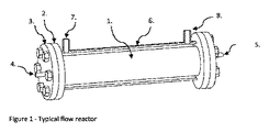
典型的な流通式反応装置が図1に示されており、この流通式反応装置は、通常、各端(2)のところにバッキングフランジを備えた円形の管であるチャネル(1)から成っている。封止フランジ(3)が密閉システムを形成するようバッキングフランジにボルト留めされている。管は、周囲圧力、高い圧力又は真空下において動作するときにゆがみ又は損傷に抵抗するのに適した機械的強度を提供する材料で製作される。管は、種々の金属、例えばステンレス鋼、ハステロイ、炭素鋼等で製作されるのが良い。変形例として、管は、ガラス、セラミック材料又はそれどころかプラスチックで製作されても良い。高い機械的強度と良好な耐食性の組み合わせが必要な場合、反応装置本体は、一材料で製作され、そして別の材料で被覆され又は内張りされるのが良い。供給パイプ(4)が一端側のフランジに取り付けられた状態で示され、排出パイプ(5)が反対側のフランジに取り付けられた状態で示されている。多数本の供給パイプ及び排出パイプを用いることができ、これらパイプのうちの何本かは、管に沿う中間箇所のところに配置されるのが良い。冷却ジャケット(6)が示されており、この冷却ジャケットは、熱を加え又は除くために用いられる。熱伝達供給パイプ(7)は、ジャケットの一端のところに示され、熱流体排出パイプ(8)は、ジャケットの他端のところに示されている。温度制御システムについては上述した。幾つかのシステムに関し、他の加熱又は冷却形態、例えば、電気発熱体又はペルティエ素子を利用することができる。上述の説明は、例示目的のためであり、この構成の多くの変更例及び変形例が可能である。 A typical flow reactor is shown in FIG. 1, which consists of a channel (1), which is usually a circular tube with a backing flange at each end (2). Yes. The sealing flange (3) is bolted to the backing flange to form a closed system. The tube is made of a material that provides mechanical strength suitable to resist warping or damage when operating under ambient pressure, high pressure or vacuum. The tube may be made of various metals such as stainless steel, hastelloy, carbon steel and the like. As a variant, the tube may be made of glass, ceramic material or even plastic. If a combination of high mechanical strength and good corrosion resistance is required, the reactor body may be made of one material and coated or lined with another material. The supply pipe (4) is shown attached to one end flange, and the discharge pipe (5) is shown attached to the opposite flange. Multiple supply and discharge pipes can be used, and some of these pipes should be located at intermediate points along the pipe. A cooling jacket (6) is shown, which is used to add or remove heat. A heat transfer supply pipe (7) is shown at one end of the jacket and a thermal fluid discharge pipe (8) is shown at the other end of the jacket. The temperature control system has been described above. For some systems, other heating or cooling configurations, such as electric heating elements or Peltier elements, can be utilized. The above description is for illustrative purposes, and many variations and modifications of this configuration are possible.
図2は、ダイナミック型攪拌器、シャフト及びシャフト取り付けカラーの分解組立て詳細図である。攪拌器(9)は、中心に円形の穴を備えた中央ボス(10)を有している。多数枚の混合羽根(11)がボスに取り付けられている。羽根は、図示のように単純なパドルであるのが良いが、これら羽根は又、ピッチ付きタービン、多数の薄い羽根、ワイヤ、メッシュ又は任意他の形状のものであっても良い。1つ(又は2つ以上)の羽根(12)の質量(重量)は、大きい。図中、質量の増大は、羽根を物理的に大きく作ることによって達成される。代替的に又は追加的に、羽根は、他の羽根と同一サイズのものであって良いが、より高密度の材料で製作されるのが良い。攪拌器は、遊び嵌め状態でシャフト(13)に取り付けられている。攪拌器シャフト及びボスの内部穴は、滑らかな低摩擦性表面を有するべきである。プロセス材料が研磨性固形分を含む場合、移動している表面を保護するためにOリング又は軟質ブッシュが用いられるのが良い。攪拌器シャフト(13)は、シャフトがシャフト支持カラー(14)を中心として回転するのを阻止するようその周囲に平坦なフェースを有する。シャフトの他の形状又は別の方法、例えば止めナットを用いると、シャフトを固定位置に保つことができる。シャフト支持カラーは、攪拌器シャフトを保持するよう反応装置本体の各端のところに設けられている。シャフト支持カラーは、反応装置の端フランジの一部をなしても良く、或いは、管の端のところに設けられた別個のフレーム又はプレートに取り付けられても良い。反応装置内における攪拌器シャフトの好ましい位置は、中央軸線に沿う位置である。しかしながら、幾つかの用途に関し、攪拌器シャフトは、中央が取り付けられなくても良く、他の場合、2本又は3本以上の攪拌器シャフトが用いられても良い。 FIG. 2 is a detailed exploded view of the dynamic agitator, shaft and shaft mounting collar. The stirrer (9) has a central boss (10) with a circular hole in the center. Multiple mixing blades (11) are attached to the boss. The vanes may be simple paddles as shown, but these vanes may also be of pitched turbine, multiple thin vanes, wires, mesh or any other shape. The mass (weight) of one (or more) blades (12) is large. In the figure, the increase in mass is achieved by making the vanes physically larger. Alternatively or additionally, the vanes may be the same size as the other vanes, but may be made of a higher density material. The stirrer is attached to the shaft (13) in a play-fit state. The stirrer shaft and boss internal holes should have a smooth, low friction surface. If the process material contains abrasive solids, an O-ring or soft bushing may be used to protect the moving surface. The agitator shaft (13) has a flat face around it to prevent the shaft from rotating about the shaft support collar (14). The shaft can be held in a fixed position using other shapes of the shaft or other methods, such as a lock nut. A shaft support collar is provided at each end of the reactor body to hold the stirrer shaft. The shaft support collar may form part of the end flange of the reactor, or it may be attached to a separate frame or plate provided at the end of the tube. A preferred position of the stirrer shaft within the reactor is a position along the central axis. However, for some applications, the agitator shaft may not be centered, and in other cases, two or more agitator shafts may be used.
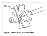
図3は、スタティック型攪拌器、シャフト及びシャフト取り付け部の分解組立て詳細図である。攪拌器(15)は、シャフトに固定されており、この攪拌器は、この実施形態では、シャフトを中心とした回転を阻止するようシャフトのアールに設けられた平坦なスポットを用いている。攪拌器をシャフト上に固定する他の方法を使用することができる。
スタティック型及びダイナミック型攪拌器は、剛性であっても良く可撓性であっても良い。可撓性攪拌器は、攪拌器シャフトの回転方向が変化するときに大きな先端部の動きをもたらすことになる。これにより、混合性能が向上し、これら攪拌器は、曲げ及び混合硬化を高めるよう先端部のところに重りが付けられるのが良い。
FIG. 3 is an exploded detailed view of the static stirrer, the shaft, and the shaft mounting portion. The stirrer (15) is fixed to the shaft, and in this embodiment, the stirrer uses a flat spot provided on the radius of the shaft so as to prevent rotation about the shaft. Other methods of securing the stirrer on the shaft can be used.
The static and dynamic stirrers may be rigid or flexible. A flexible stirrer will cause a large tip movement when the direction of rotation of the stirrer shaft changes. This improves mixing performance and these stirrers should be weighted at the tip to enhance bending and mixing hardening.
図4は、反応装置本体を示している。これは、反応装置の本体が回転できるようにする軸受(17)に取り付けられた管(16)として示されている。反応装置が回転することができるようにする軸受は、反応装置本体の周りに示されているが、変形例として、反応装置の端又は本体から突き出た回転クレードル又はシャフト内に設けられても良い。変形例として(軸受の変形例として)、ゴムブッシュ、ばね、低摩擦性スリーブ又は他の可撓性器具を用いて反応装置本体が回転することができるようにしても良い。好ましい回転軸線は、反応装置管の中心軸線である。しかしながら、変形例として、回転軸線は、中心から外れていても良く、例えば、スイングアーム上に位置していても良い。また、駆動機構体(18)が示されており、この駆動機構体により、反応装置は、取り付け部を中心として往復動アークをなして回転する。駆動機構体は又、エネルギーを節約し、その移動の終わりに回転アークを逆にするのを助けるためのリコイルばね、空気圧ピストン又は他の装置(一方の要素は、固定物体に取り付けられ、他方の要素は、回転反応装置に取り付けられる)によって支援されるのが良い。図示の駆動機構体は、空気圧又は油圧ピストンである。別の駆動機構体、例えば歯車、コグ(cog )、モータ、電磁装置等を用いても良い。駆動機構体は、反応装置を往復動アーク状態で(時計回りに、次に反時計回りに又はこれらの逆の関係が成り立つ)回転させる。最大回転度は、360°である。しかしながら、回転度は、用途に応じて様々であり、好ましい回転度は、1°〜90°である。乱流条件下で動作する反応装置本体の回転度は、反応装置容積部全体を通じて乱流を発生させるほど大きいことが必要であり、これは、多くの要因で決まることになる。層流条件下における反応装置本体の回転度は、管空間の最大容積が攪拌器羽根によって掃過されるようなものであるべきである。かかる場合における羽根の好ましい最小枚数は、(360)/nであり、この場合、nは、用いられる混合羽根の枚数である。ブレードの厚さを考慮に入れるために360という値を減少させることができる。より好ましい回転アークは、45°未満である。回転速度は、用途及び回転度に応じて様々であり、毎分1回転未満から毎秒10サイクル超まで様々であろう。 FIG. 4 shows the reactor main body. This is shown as a tube (16) attached to a bearing (17) that allows the body of the reactor to rotate. Bearings that allow the reactor to rotate are shown around the reactor body, but may alternatively be provided in a rotating cradle or shaft protruding from the end or body of the reactor. . As a variation (as a variation of the bearing), the reactor body may be rotated using a rubber bush, spring, low friction sleeve or other flexible instrument. A preferred axis of rotation is the central axis of the reactor tube. However, as a modification, the rotation axis may be off the center, for example, may be located on a swing arm. Also shown is a drive mechanism (18) by which the reactor rotates in a reciprocating arc around the attachment. The drive mechanism also saves energy and recoiling springs, pneumatic pistons or other devices to help reverse the rotating arc at the end of its movement (one element is attached to a fixed object and the other is The element may be assisted by being attached to a rotating reactor). The illustrated drive mechanism is a pneumatic or hydraulic piston. Other drive mechanisms, such as gears, cogs, motors, electromagnetic devices, etc. may be used. The drive mechanism rotates the reactor in a reciprocating arc state (clockwise, then counterclockwise, or vice versa). The maximum degree of rotation is 360 °. However, the degree of rotation varies depending on the application, and the preferred degree of rotation is 1 ° to 90 °. The degree of rotation of the reactor body operating under turbulent conditions needs to be large enough to generate turbulence throughout the reactor volume, which will depend on many factors. The degree of rotation of the reactor body under laminar flow conditions should be such that the maximum volume of the tube space is swept by the stirrer blades. The preferred minimum number of blades in such a case is (360) / n, where n is the number of mixing blades used. The value of 360 can be reduced to take into account the blade thickness. A more preferred rotating arc is less than 45 °. The rotational speed will vary depending on the application and degree of rotation, and may vary from less than one revolution per minute to more than 10 cycles per second.
スタティック型ミキサによる混合‐単一管を用いることができるが、図3に示されているようなスタティック型混合要素が好ましい。というのは、これらスタティック型混合要素は、管の直径を横切って混合を生じさせるのに役立つからである。反応装置の本体を逆アーク状態で回転させると、反応装置の固定要素と流体との差動運動の組み合わせ効果により、混合が生じることになる。 Mixing with a static mixer—single tubes can be used, but a static mixing element as shown in FIG. 3 is preferred. This is because these static mixing elements help to cause mixing across the diameter of the tube. When the reactor body is rotated in a reverse arc, mixing occurs due to the combined effect of the differential motion of the reactor stationary element and the fluid.
ダイナミック型ミキサによる混合‐別の好ましい解決手段は、図2に示されているようなダイナミック型混合要素を用いることである。図示のこれら混合要素は、アンバランスであり、これら混合要素は、シャフトを中心として自由に回転することができる。反応装置の本体を回転させると、これら混合要素は、異なる速度及び相で流体及び固定攪拌器まで動くことになる。ダイナミック型ミキサの運動(速度及びアークの半径の観点において)は、プロセス材料の特性、回転ミキサの設計、反応装置本体の回転速度及び反応装置本体の回転角度に応じて様々であろう。図5に示されているように攪拌器と攪拌器シャフト上の固定された箇所との間に停止部を用いるのが良い。固定停止部(19)は、スタティック型攪拌器上に示されている。固定停止部は、主反応装置本体のシャフト上又は他の部分上に設けられても良い。移動停止部(20)がダイナミック型攪拌器に設けられた状態で示されている。停止部をこのように用いることによって、攪拌器の移動度を制限することができ、又、加速度を増大させることができる。 Mixing with a dynamic mixer-Another preferred solution is to use a dynamic mixing element as shown in FIG. The mixing elements shown are unbalanced and can be freely rotated about the shaft. As the reactor body is rotated, the mixing elements will move to the fluid and stationary agitator at different speeds and phases. The dynamic mixer motion (in terms of speed and arc radius) will vary depending on the characteristics of the process material, the design of the rotating mixer, the rotational speed of the reactor body and the rotational angle of the reactor body. A stop may be used between the stirrer and the fixed location on the stirrer shaft as shown in FIG. A fixed stop (19) is shown on the static stirrer. The fixed stop may be provided on the shaft of the main reactor main body or on another part. The movement stop part (20) is shown in the state provided in the dynamic stirrer. By using the stop in this manner, the mobility of the stirrer can be limited and the acceleration can be increased.
ダイナミック型ミキサの回転は、僅かなアークをなしたものであって良く、この場合、反応装置空間の容積を十分に掃過するようにするために多数枚のミキサ羽根の使用が望ましい。乱流条件を達成することができる場合、掃過容積の減少を許容することができる。ただし、乱流が作業容積全体まで及ぶことを条件とする。幾つかの用途では、ダイナミック型ミキサは、アークをなして動くことになり、他の場合、ダイナミック型ミキサは、一方向に連続して回転するであろう。これは、揺さぶり条件を調整して連続回転を生じさせることによって達成できる。連続回転は又、一方の回転方向の場合のほうが他方の回転方向の場合よりも抗力としての抵抗が大きいように羽根形状を設計することによって促進可能である。 The rotation of the dynamic mixer may be a slight arc, in which case it is desirable to use multiple mixer blades in order to sufficiently sweep the reactor space volume. If turbulent conditions can be achieved, a decrease in sweep volume can be tolerated. Provided that the turbulent flow reaches the entire working volume. In some applications, the dynamic mixer will move in an arc, and in other cases the dynamic mixer will rotate continuously in one direction. This can be achieved by adjusting the shaking conditions to produce continuous rotation. Continuous rotation can also be facilitated by designing the blade shape so that the resistance as a drag is greater in one direction of rotation than in the other direction.
上述の構成例の変形構成例は、ダイナミック型ミキサ(9)をシャフトに固定させると共に自由に回転するシャフトを設けることにある。この場合、シャフト支持カラーは、内側アールのところが円形であり、それによりシャフトの自由回転が可能である。 A modified configuration example of the above-described configuration example is to provide a shaft that can freely rotate while fixing the dynamic mixer (9) to the shaft. In this case, the shaft support collar is circular at the inner radius, thereby allowing free rotation of the shaft.
他の場合、特に、粘性流体に関し、ダイナミック型ミキサが一方の方向にのみ回転することができるようにするラチェット機構体又はその類似機構体を採用するのが良い。ラチェット機構体(又は停止装置)は、ロック箇所(反応装置本体に対して固定されている)と回転ミキサとの間にそれぞれ形成されている。幾つかの場合、ダイナミック型攪拌器は、互いに異なる攪拌器(通常、隣り合う攪拌器)が互いに逆の回転方向に動くよう配置されるのが良い。この場合、連続回転攪拌器は、バランスが取られていても良くアンバランスであっても良い。 In other cases, particularly with respect to viscous fluids, a ratchet mechanism or similar mechanism that allows the dynamic mixer to rotate only in one direction may be employed. The ratchet mechanism (or the stop device) is formed between the lock portion (fixed to the reaction device main body) and the rotary mixer. In some cases, the dynamic stirrer may be arranged such that different stirrers (usually adjacent stirrers) move in opposite directions of rotation. In this case, the continuous rotary stirrer may be balanced or unbalanced.
ダイナミック型ミキサ及びスタティック型ミキサによる混合‐高い混合性能を得るため、より好ましいオプションは、スタティック型ミキサとダイナミック型ミキサの組み合わせを用いることである。これらの機能的な設計は、以下の実施例で記載するように用途に応じて様々であろう。
・幾つかの混合用途に関し、高い混合度が必要とされる。これは、代表的には、迅速な配合時間が必要とされるプロセス、例えば競合反応を含むプロセスに当てはまる。これは又、2つ以上の相(不混和液、気体/液体混合物及び固体/液体混合物)が存在する場合に当てはまる。隣り合う攪拌器を互いに異なる速度で且つ/或いは互いに異なる方向で動かすことにより、良好な混合が達成される。
・粘性流体が取り扱われている場合又は良好な栓流が必要とされる場合、大きな表面積及び良好な間隙率を備えた複式ミキサの使用が好ましい。これは、流体がミキサを通って流れることができ、一方で、多数の箇所で分割されるような複合構造体であるべきである。両方の複式ミキサに関する半径方向混合距離は、幾つかの用途については短く、これにより、直径を横切る組成及び温度の勾配が生じる場合がある。これは、互いに異なる種類のミキサを用いることによって取り組み可能である。図6は、複式ミキサ(21)を示している。複式ミキサ相互間には、単式ミキサ(22)が設けられている。単式ミキサは、管の大きな外周部にわたって混合を生じさせ、従って、直径を横切ってプロセス材料を再分布させる。単式ミキサは、高度の逆混合を生じさせるので、単式ミキサ要素(22)により占められる管の軸方向長さは、できるだけ短いことが望ましい。変形例として、そらせ板の孔の位置は、流れをミキサ相互間に再分布させるために使用できる。このために、そらせ板の孔は、そらせ板の周囲のところ、そらせ板作業面の内側アールのところ又は中間箇所のところに集中して設けられるのが良い。好ましい配置場所は、そらせ板の周囲、そらせ板の作業表面の内側アールのところ相互間の中間箇所のところにあり、或いは、この中間箇所から僅かにオフセットしている。
・水平管又はほぼ水平管中の互いに異なる密度の多相混合物を取り扱う際、密度の高い方の相材料が管の下半分に集まる傾向がある。かかる用途では、本明細書において説明しているような反応装置は、2つの機能を実行することができる。ダイナミック型ミキサは、良好な混合を促進するが、大きなアークをなして旋回することにより(反応装置が回転するのではなく)又は連続的に回転することによって垂直平面内で軽く且つ高密度の相を再分布させることもできる。これは、より密度の高い材料を持ち上げ、軽い材料を押し下げる傾向がある。そのようにすることによって、これは、迅速な反応をもたらす界面相接触を増大させる。
Mixing with dynamic and static mixers—To obtain high mixing performance, a more preferred option is to use a combination of static and dynamic mixers. These functional designs will vary depending on the application as described in the examples below.
• For some mixing applications, a high degree of mixing is required. This is typically the case for processes where rapid compounding times are required, such as processes involving competitive reactions. This is also true when more than one phase is present (immiscible liquid, gas / liquid mixture and solid / liquid mixture). Good mixing is achieved by moving adjacent stirrers at different speeds and / or in different directions.
• When viscous fluids are being handled or when good plug flow is required, the use of a dual mixer with a large surface area and good porosity is preferred. This should be a composite structure that allows fluid to flow through the mixer while being split at multiple locations. The radial mixing distance for both duplex mixers is short for some applications, which can result in composition and temperature gradients across the diameter. This can be addressed by using different types of mixers. FIG. 6 shows a duplex mixer (21). A single mixer (22) is provided between the duplex mixers. A single mixer causes mixing over the large circumference of the tube, thus redistributing the process material across the diameter. Since single mixers produce a high degree of backmixing, it is desirable that the axial length of the tube occupied by the single mixer element (22) be as short as possible. As a variant, the position of the baffle holes can be used to redistribute the flow between the mixers. For this purpose, the holes of the baffle plate are preferably provided in a concentrated manner around the baffle plate, at the inner radius of the baffle plate working surface or at an intermediate point. A preferred location is at the perimeter of the baffle, at the inner radius of the working surface of the baffle, at a midpoint between them, or slightly offset from this midpoint.
• When handling multi-phase mixtures of different densities in horizontal tubes or nearly horizontal tubes, the denser phase material tends to collect in the lower half of the tube. In such applications, a reactor as described herein can perform two functions. Dynamic mixers promote good mixing, but light and dense phases in a vertical plane by swirling in a large arc (rather than rotating the reactor) or by continuous rotation. Can be redistributed. This tends to lift the denser material and push the lighter material down. By doing so, this increases the interfacial contact resulting in a rapid reaction.
ミキサの直径は、反応装置管直径の10%から用途で決まる直径全体まで様々であって良い。好ましい直径は、単純な羽根、例えば図3に符号(15)で示された羽根については管直径の40%〜70%である。これら直径は、羽根車がダイナミック混合を生じさせることができる低粘度流体について又は図6に符号(22)で示されているような半径方向平面内における再分布について好ましい。図6に符号(21)で示された複式ミキサ又はディスク形羽根は、好ましくは、回転するに足るほどの隙間があることを条件として、反応装置管の外周部全体に設けられる。 The mixer diameter can vary from 10% of the reactor tube diameter to the entire diameter as determined by the application. The preferred diameter is 40% to 70% of the tube diameter for a simple vane, for example the vane indicated by reference numeral (15) in FIG. These diameters are preferred for low viscosity fluids where the impeller can cause dynamic mixing or for redistribution in a radial plane as indicated by reference numeral (22) in FIG. The duplex mixer or disk-shaped blade indicated by reference numeral (21) in FIG. 6 is preferably provided on the entire outer periphery of the reactor tube, provided that there is sufficient clearance to rotate.
攪拌器シャフトは、攪拌器の荷重を支持するのに足るほど強固であるべきであり且つダイナミック型攪拌器が用いられる場合、理想的には低摩擦材料で製作されるべきである。ダイナミック型攪拌器の内面も又、低摩擦材料であるべきである。これらは又、摩耗部品を交換することができるようシャフトよりも軟質の材料で製作されても良い(又は、これとは逆の関係が成り立つ)。 The stirrer shaft should be strong enough to support the stirrer load and should ideally be made of a low friction material when a dynamic stirrer is used. The inner surface of the dynamic stirrer should also be a low friction material. They may also be made of a softer material than the shaft so that wear parts can be replaced (or vice versa).
一揃いの形状及びサイズのミキサを採用することができ、かかるミキサは、バランスが取られており又はアンバランスな円筒形ミキサを含む。高い剪断力又は単位体積当たりの大きな熱伝達面積が必要な場合に円筒形ミキサが用いられる。筒体を用いることによって、内側管容積を減少させて表面積と体積の高い比をもたらすことができ、必要な場合、攪拌器と管の内壁との間に狭い空間を設けることによって高い剪断力をもたらすことができる。 A set of shapes and sizes of mixers can be employed, and such mixers include balanced or unbalanced cylindrical mixers. Cylindrical mixers are used when high shear forces or large heat transfer areas per unit volume are required. By using a cylinder, the inner tube volume can be reduced resulting in a high surface area to volume ratio, and if necessary, high shear forces can be achieved by providing a narrow space between the agitator and the tube inner wall. Can bring.
図7のそらせ板(23)は、逆混合を阻止するために用いられる。これらそらせ板は、ミキサシャフトに取り付けられた有孔板であり、かかるそらせ板は、プロセス材料が反らせ板を横切ってしか一方向に移動することがないよう流れ領域を制限する。そらせ板に設けられた穴に加え又はこれら穴の代替手段として、頂部又は底部のところの周囲に切り欠きを用いて軽い又は重い材料がそれぞれ、そらせ板相互間に堆積するのを阻止するのが良い。そらせ板は、互いに異なる直径のものであって良いが、代表的には、そらせ板が管内に滑り込むことができるようにする最大直径のものである。そらせ板は又、シャフトを支持し、攪拌器による曲げ力が大きい場合、過度の曲げを阻止するために使用できる。これにより、支持そらせ板が設けられていない場合に必要な細さよりも細い攪拌器シャフトの使用が可能である。そらせ板及びミキサの種々の構成例を利用することができる。図7は、3つのミキサ、即ち、2つのダイナミック型ミキサ及び1つのスタティック型ミキサにより隔てられた2枚のそらせ板を示している。単式ミキサが用いられる場合、5枚又は6枚以上のそらせ板が反応装置管1本当たりに用いられ(反応装置システムが多数本の管を有している場合がある)、より好ましくは10枚又は11枚以上のそらせ板が反応装置管1本当たりに用いられる。 The baffle plate (23) of FIG. 7 is used to prevent backmixing. These baffles are perforated plates attached to the mixer shaft that limit the flow area so that the process material can only move in one direction across the baffle. In addition to or as an alternative to the holes provided in the baffles, it is possible to use a notch around the top or bottom to prevent light or heavy materials from accumulating between the baffles, respectively. good. The baffles can be of different diameters, but are typically of the largest diameter that allows the baffle to slide into the tube. The baffle also supports the shaft and can be used to prevent excessive bending if the bending force by the stirrer is large. As a result, it is possible to use a stirrer shaft that is thinner than necessary when no support deflector is provided. Various configuration examples of the baffle plate and the mixer can be used. FIG. 7 shows two baffles separated by three mixers: two dynamic mixers and one static mixer. When a single mixer is used, 5 or more baffles are used per reactor tube (the reactor system may have multiple tubes), more preferably 10 Alternatively, 11 or more baffles are used per reactor tube.
プロセス材料を供給する入口連結部及びプロセス材料を排出する出口連結部は、順序正しい流れが得られるよう且つ反応装置管の長さの全体的使用が達成されるよう最大距離を離したところで管に取り付けられるべきである。これら連結部は、端板に取り付けられる。供給パイプ及び排出パイプを切り離すことなく、端板に接近する必要がある場合、供給連結部及び排出連結部は、それぞれの端板から最小距離を置いたところで管の壁に取り付けられる。多数の付加(例えば、気体/液体反応又は反応装置の冷却能力を超える反応)を行う必要性があるプロセスの場合、多数の追加箇所が管の長さに沿って設けられるのが良い。 An inlet connection for supplying process material and an outlet connection for discharging process material are connected to the tube at a maximum distance so that an in-order flow is obtained and overall use of the reactor tube length is achieved. Should be mounted. These connecting portions are attached to the end plate. If it is necessary to approach the end plates without disconnecting the supply and discharge pipes, the supply and discharge connections are attached to the tube wall at a minimum distance from the respective end plates. For processes that require multiple additions (eg, gas / liquid reactions or reactions that exceed the cooling capacity of the reactor), multiple additional points may be provided along the length of the tube.
反応装置管を水平に設けても良く、垂直に設けても良く、或いは勾配をなして設けても良い。勾配は、自由排出が必要な場合に好ましく、或いは、2つの相が存在する場合、反応装置管に沿って軽い又は重い材料の動きを助けるために好ましい(浮遊材料を取り扱うために上方への勾配及び沈降材料については下方への勾配)。プロセス材料が互いに異なる密度の2つ又は3つ以上の相を有している場合、水平又はほぼ水平の管が好ましい。反応装置管は、軸方向平面内で分割されても良いが、好ましい構成例は、一体の管である。 The reactor tube may be provided horizontally, vertically, or provided with a gradient. A gradient is preferred when free draining is required, or when two phases are present, to help move light or heavy materials along the reactor tube (upward gradient to handle suspended material) And downward slope for sedimented material). Horizontal or nearly horizontal tubes are preferred when the process material has two or more phases of different densities. The reactor tube may be divided in an axial plane, but a preferred configuration is an integral tube.
反応装置管の長さは、要望に応じて様々であり、50ミリメートル以下から10メートル以上までの場合があるが、より好ましくは、0.5メートルから3メートルまで様々である。短い管は、ミキサ組立体を挿入したり取り外したりするために良好な接近を可能にする。管長さが3メートルを超え、より好ましくは2メートルを超える場合、好ましくは可撓性連結部によって互いに結合された多数本の管を用いることが好ましい。 The length of the reactor tube may vary as desired and may be from 50 millimeters to 10 meters or more, more preferably from 0.5 meters to 3 meters. The short tube allows good access for inserting and removing the mixer assembly. If the tube length is greater than 3 meters, more preferably greater than 2 meters, it is preferable to use multiple tubes that are preferably joined together by flexible connections.
反応装置管の直径は、用途に応じて様々であり、1ミリメートル未満から2メートルを超えるまで様々であって良い。迅速な反応及び発熱反応(代表的には、反応時間が1分未満)の場合、直径が5ミリメートルから50ミリメートルまでの範囲にある管が好ましい。単位体積当たりの反応装置のコストは、大径の管を用いた場合でも低く、従って、可能である場合、最大直径の管が望ましい。反応時間が1分よりも長く、熱伝達上の要望によって拘束されていない場合、50ミリメートルから500ミリメートルまでの大径の管が好ましい。反応速度が変化すると仮定すると、多くの用途にとって好ましい解決手段は、直列に連結された多数本の管を用いることであり、又、反応速度の変化に合うようにそれぞれの管の直径が同一であっても良く、異なっていても良い。 The diameter of the reactor tube varies depending on the application and can vary from less than 1 millimeter to more than 2 meters. For rapid and exothermic reactions (typically a reaction time of less than 1 minute), tubes with diameters ranging from 5 millimeters to 50 millimeters are preferred. The cost of the reactor per unit volume is low even with large diameter tubes, so the largest diameter tube is desirable when possible. Larger pipe diameters from 50 to 500 millimeters are preferred when the reaction time is longer than 1 minute and is not constrained by heat transfer requirements. Assuming that the reaction rate changes, the preferred solution for many applications is to use multiple tubes connected in series, and each tube has the same diameter to accommodate the change in reaction rate. May be different or different.
適正な構成材料及び材料の厚さの選択がなされることを条件として、反応装置を広い圧力及び温度範囲にわたって動作させることができる。プロセス材料の封じ込めは、可動継手、例えば機械的シールが設けられていないことによって助長される。 The reactor can be operated over a wide pressure and temperature range, provided that the proper component materials and material thicknesses are selected. Containment of process material is facilitated by the absence of movable joints, such as mechanical seals.
システムは、一方向流れ又は向流用に使用できる。向流では、2種類の流体が反応要素うちの管の互いに異なる端のところで供給され、各流体は、それぞれの互いに反対側の端で出る。この方法は、幾つかの形式の反応及び更に抽出に利用できる。かかるプロセスが働くようにするためには、向流流れは、互いに実質的に不溶性であり且つ互いに異なる密度のものでなければならない。向流システムは、反応装置の各端のところに非混合分離ゾーンを含むと共に反応装置の長さに沿う段のところに中間の分離ゾーンを含むのが良い。 The system can be used for unidirectional or counterflow. In counterflow, two types of fluid are supplied at different ends of the tubes of the reaction elements, with each fluid exiting at its opposite end. This method can be used for several types of reactions and further extractions. In order for such a process to work, the countercurrent flows must be substantially insoluble from each other and of different densities. The countercurrent system may include an unmixed separation zone at each end of the reactor and an intermediate separation zone at a stage along the length of the reactor.
流通式反応装置は、流体を固定された物体、例えばタンクやポンプから回転反応装置本体に移送するための供給パイプ及び排出パイプを必要とする。これらパイプは、反応装置本体の回転運動を吸収するのに十分な可撓性を備えなければならない。運動が僅かである場合、十分な長さを備えた剛性の連結パイプを用いることができ、かかる連結パイプは、運動の応力を吸収するよう曲がる。運動の程度が大きい場合、長いアールの曲げ部を備えた剛性のパイプを用いることができ、或いは、可撓性管、例えばプラスチック管又は波形金属管を用いることができる。 The flow reactor requires a supply pipe and a discharge pipe for transferring a fluid from a fixed object such as a tank or a pump to the rotary reactor main body. These pipes must be flexible enough to absorb the rotational movement of the reactor body. If the movement is slight, a rigid connecting pipe with sufficient length can be used, and such connecting pipe bends to absorb the stress of movement. If the degree of motion is large, a rigid pipe with a long round bend can be used, or a flexible tube, such as a plastic tube or a corrugated metal tube, can be used.
良好な栓流は、反応装置内におけるプロセス材料の滞留時間を制御するのに必要な一パラメータである。他のパラメータは、制御された供給速度でのプロセス材料の送出である。これは、計量ポンプ、流量が較正された非計量ポンプ、一定且つ較正された水頭での重力供給方式の使用により達成できる。供給速度は又、流量測定装置、コントローラ及び制御要素、例えば流量を調整する流量制御弁を含む流量制御システムを用いて制御できる。 Good plug flow is one parameter necessary to control the residence time of the process material in the reactor. Another parameter is the delivery of process material at a controlled feed rate. This can be achieved by the use of a metering pump, a non-metering pump with a calibrated flow rate, a constant and calibrated head of gravity feed. The feed rate can also be controlled using a flow control system that includes a flow measuring device, a controller and control elements, such as a flow control valve that regulates the flow rate.
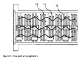
図8は、反応装置中のプロセス材料の流路を示している。図8で用いられている攪拌器は、中央ハブに取り付けられたスポークであり、但し、他の形式の攪拌器を用いることができる。スタティック型攪拌器(24)及びダイナミック型攪拌器(25)は、反応装置の直径を横切って多数の箇所(26)のところで、好ましくは反応装置直径の20%を超え、より好ましくはこの直径の50%を超えて攪拌器を超える軸方向流れを可能にする。このことは、流路の公称長さが反応装置管の長さに等しい(半径方向混合の作用効果を差し引いて)ことを意味している。しかしながら、そらせ板(上述したようなそらせ板)が1つ又は2つ以上のアールまでのこれらそらせ板を超える流れを制限するために用いられる場合、公称流路は長いのが良い。本発明は、2つ以上の密度のプロセス材料が存在する場合に好ましい。攪拌器を超える軸方向流れを反応装置管の1つのアールのところに設けられた小さな孔に制限する同時特許出願が同日に出願されている。 FIG. 8 shows the process material flow path in the reactor. The stirrer used in FIG. 8 is a spoke attached to a central hub, although other types of stirrers can be used. The static stirrer (24) and the dynamic stirrer (25) are at multiple points (26) across the reactor diameter, preferably more than 20% of the reactor diameter, more preferably of this diameter. Allows axial flow in excess of 50% beyond the stirrer. This means that the nominal length of the flow path is equal to the length of the reactor tube (minus the effect of radial mixing). However, if baffles (a baffle as described above) are used to restrict flow beyond these baffles to one or more are, the nominal flow path may be long. The present invention is preferred when more than one density of process material is present. A co-pending patent application is filed on the same day that restricts the axial flow beyond the stirrer to a small hole at one radius of the reactor tube.
本発明の特徴は、次の通りである。
・反応装置内における混合を生じさせるよう反応装置の本体を往復動アーク状態で回転させる。これにより、機械的シール又は磁気結合により外部駆動ユニットに連結される攪拌器シャフトが不要になる。
・回転を360°以下のアークに制限することによって、反応装置本体を可撓性流体移送パイプ、電気ケーブル及び計器ケーブルによって固定状態の物体に連結することができる。回転方向を繰り返し逆にすることによって、攪拌器は、互いに異なる速度で且つ流体に対して互いに異なるサイクル方向のうちの幾つかの部分で動き、それにより、混合具合の向上がもたらされる。また、アークを逆にするという使用により、高い回転速度の必要性が緩和され、かくして、シャフト又はダイナミック型攪拌器に生じる摩耗が減少する。
・内部特徴部(例えば、そらせ板)を設けないで単一の管として反応装置本体を製作することができる。攪拌器組立体をこの管内に押し込み又は引き込むことができる。この設計により、製作費が減少すると共にクリーニング及び保守が単純になる。
・細い攪拌器シャフトを用いることができる。というのは、この細い攪拌器シャフトは、反応装置の本体に対して固定され、中間箇所で支持できるからである。
・スタティック型及びダイナミック型ミキサの組み合わせの使用により、混合具合の向上が得られる。
・図2に示された平坦なフェース(13)(又はその類似物)を有する攪拌器シャフトの使用により、そらせ板及び攪拌器を定位置に押すことができ、また、そらせ板及び攪拌器がこれらの内部形状に応じて、シャフトを中心として回転し又はシャフトに固定された状態のままであることが許容されるようになる。
The features of the present invention are as follows.
Rotate the reactor body in a reciprocating arc to cause mixing in the reactor. This eliminates the need for a stirrer shaft connected to the external drive unit by mechanical sealing or magnetic coupling.
By limiting the rotation to an arc of 360 ° or less, the reactor body can be connected to a stationary object by flexible fluid transfer pipes, electrical cables and instrument cables. By repeatedly reversing the direction of rotation, the stirrer moves at different speeds and in different parts of the cycle direction relative to the fluid, thereby providing improved mixing. Also, the use of reversing arcs alleviates the need for high rotational speeds, thus reducing wear on shafts or dynamic stirrers.
-The reactor body can be manufactured as a single tube without the internal features (e.g. baffle). The stirrer assembly can be pushed or pulled into this tube. This design reduces manufacturing costs and simplifies cleaning and maintenance.
-A thin stirrer shaft can be used. This is because this thin stirrer shaft is fixed to the body of the reactor and can be supported at an intermediate location.
• Use of a combination of static and dynamic mixers can improve mixing.
• The use of a stirrer shaft with a flat face (13) (or the like) shown in FIG. 2 can push the baffle plate and stirrer into place, and the baffle plate and stirrer Depending on their internal shape, it is allowed to rotate about the shaft or remain fixed to the shaft.
本願の発明は、このシステムの攪拌器が固定された軸の一部であり又はこの固定された軸を中心として回転するという点で、国際公開第2008/068019号パンフレット及び同第2011/124365号パンフレットに記載された先行技術とは異なっている。本発明は、スタティック型ミキサを備えたスタティック混合原理、ダイナミック型ミキサを備えたダイナミック混合原理又はこれら2つの組み合わせを具体化している。上述した先行技術とは異なり、これにより、攪拌器と反応装置本体の衝突が阻止され、しかも攪拌器の位置を固定することができ、その結果、反応装置管の外周部における最適位置を達成することができる。これら特徴は、管の直径が50mm未満であるシステムに利用できるが、管直径が50mmを超える大型システムでは一層望ましい。 The invention of the present application is such that the stirrer of this system is part of a fixed shaft or rotates around this fixed shaft, WO 2008/068019 and 2011/124365. It is different from the prior art described in the pamphlet. The present invention embodies the static mixing principle with a static mixer, the dynamic mixing principle with a dynamic mixer, or a combination of the two. Unlike the prior art described above, this prevents the stirrer and the reactor body from colliding and also allows the position of the stirrer to be fixed, thereby achieving the optimum position at the outer periphery of the reactor tube. be able to. These features can be used in systems where the tube diameter is less than 50 mm, but are more desirable in large systems where the tube diameter is greater than 50 mm.
本発明の商業的用途は様々である。本発明の価値は、性能と製作費の両方に関連している。
・非均質材料を取り扱うプロセスに関し、この反応装置は、効果的な混合と水平な(又はほぼ水平な)取り付け部により高い物質移動速度を提供する。水平取り付け部の重要性は、重い相材料を持ち上げなければならない距離が垂直に取り付けられた管の場合よりも短いということにある(軽い相については逆の関係が成り立つ)。この設計は又、大径管及び良好な混合が望ましいスラリの取り扱いに好適である。
・流通式反応装置の所要の容量は、次のようにして求められる。
容量(リットル)=体積流量(リットル/秒)×反応時間(秒)
高い容量が必要とされる場合、コスト及び最小限の圧力降下に関する理由で短い大径の管を用いることが好ましい。本発明は、管を通る流体速度とは無関係に効率的な混合を達成することができるダイナミック混合型流通式反応装置を提供する。これにより、混合効率を損なわないで大径の管を低い流体速度で利用することができる。この理由で、この種の反応装置を高い容量が必要な広範な用途に利用することができる。この種の反応装置は、100ミリリットル未満の容量で効率的に動作することができるが、これら反応装置は、管1本当たり最高100リットル以上までのシステムについて経済的な解決策となる。
The commercial use of the present invention varies. The value of the present invention is related to both performance and production costs.
• For processes that handle non-homogeneous materials, the reactor provides high mass transfer rates due to effective mixing and horizontal (or nearly horizontal) fittings. The importance of the horizontal mount is that the distance that the heavy phase material has to be lifted is shorter than in the case of vertically mounted tubes (the opposite relationship holds for light phases). This design is also suitable for handling large diameter tubes and slurries where good mixing is desirable.
-The required capacity of the flow reactor is determined as follows.
Volume (liter) = Volume flow rate (liter / second) x Reaction time (second)
If a high capacity is required, it is preferable to use a short large diameter tube for reasons related to cost and minimal pressure drop. The present invention provides a dynamic mixing flow reactor that can achieve efficient mixing regardless of the fluid velocity through the tube. Thereby, a large diameter pipe | tube can be utilized at low fluid velocity, without impairing mixing efficiency. For this reason, this type of reactor can be used in a wide range of applications where high capacity is required. Although this type of reactor can operate efficiently with a volume of less than 100 milliliters, these reactors represent an economical solution for systems up to 100 liters per tube and up.
本発明の第2の実施形態は、図2及び図3を参照してそれぞれ説明した回転ミキサ要素及び固定ミキサ要素を備えた回転シャフトであり、この場合、シャフトは、回転し、機械的シール又は磁気結合により外部駆動ユニットによって駆動される。上述した説明の場合と同様、回転を逆にする。外部駆動ユニットを用いると、両方の攪拌器は、反応装置本体に対して動くが、互いに異なる速度で動く。 A second embodiment of the present invention is a rotating shaft with a rotating mixer element and a stationary mixer element described with reference to FIGS. 2 and 3, respectively, in which case the shaft rotates and is mechanically sealed or It is driven by an external drive unit by magnetic coupling. As in the case described above, the rotation is reversed. With an external drive unit, both agitators move relative to the reactor body, but move at different speeds.
Claims (25)
Applications Claiming Priority (3)
| Application Number | Priority Date | Filing Date | Title |
|---|---|---|---|
| GB1219476.7 | 2012-10-30 | ||
| GB1219476.7A GB2507487A (en) | 2012-10-30 | 2012-10-30 | Rotating flow reactor |
| PCT/EP2013/072739 WO2014068011A2 (en) | 2012-10-30 | 2013-10-30 | Improved flow reactor |
Publications (2)
| Publication Number | Publication Date |
|---|---|
| JP2016502453A true JP2016502453A (en) | 2016-01-28 |
| JP2016502453A5 JP2016502453A5 (en) | 2016-12-22 |
Family
ID=47358849
Family Applications (1)
| Application Number | Title | Priority Date | Filing Date |
|---|---|---|---|
| JP2015538505A Pending JP2016502453A (en) | 2012-10-30 | 2013-10-30 | Flow reactor |
Country Status (7)
| Country | Link |
|---|---|
| US (1) | US10632449B2 (en) |
| EP (1) | EP2914371A2 (en) |
| JP (1) | JP2016502453A (en) |
| CN (1) | CN104822446B (en) |
| GB (1) | GB2507487A (en) |
| IN (1) | IN2015DN03926A (en) |
| WO (1) | WO2014068011A2 (en) |
Cited By (1)
| Publication number | Priority date | Publication date | Assignee | Title |
|---|---|---|---|---|
| JP7431725B2 (en) | 2017-09-28 | 2024-02-15 | アッシュ モリス リミテッド | Improved mixer for flow systems |
Families Citing this family (9)
| Publication number | Priority date | Publication date | Assignee | Title |
|---|---|---|---|---|
| KR101424610B1 (en) | 2013-06-14 | 2014-08-04 | (주) 라미나 | An Apparatus of Core-Shell Particles and Preparation Methods Using Thereof |
| KR20170117025A (en) * | 2015-02-13 | 2017-10-20 | 도오레 화인케미칼 가부시키가이샤 | Method for producing compound having n,n-bis(2-hydroxy-3-chloropropyl)amino group |
| GB2547248A (en) * | 2016-02-12 | 2017-08-16 | Ashe Morris Ltd | Rotating tube mixer |
| IL261228B2 (en) * | 2016-02-26 | 2023-12-01 | Nanotech Energy Inc | Methods, devices and systems for processing of carbonaceous compositions |
| CN106362662B (en) * | 2016-09-27 | 2018-07-27 | 郑州峰泰纳米材料有限公司 | A kind of melamine resin process units with continuous increasing stick effect |
| TW201819046A (en) * | 2016-11-18 | 2018-06-01 | 嘉強 陳 | A mist generating apparatus for use in a vehicle |
| NL2025396B1 (en) * | 2020-04-22 | 2021-10-28 | Hosokawa Micron B V | Processing device for processing one or more flowable materials |
| GB2603456A (en) * | 2021-01-07 | 2022-08-10 | Ashe Robert | Improved method and apparatus plug flow system |
| CN112944085B (en) * | 2021-02-04 | 2022-12-06 | 西安交通大学 | Structure and method for improving thermal stratification phenomenon in branch-shaped channel |
Citations (9)
| Publication number | Priority date | Publication date | Assignee | Title |
|---|---|---|---|---|
| JPS5721023U (en) * | 1980-07-07 | 1982-02-03 | ||
| JPH10213379A (en) * | 1997-01-29 | 1998-08-11 | Techno Koa:Kk | Furnace core pipe for rotary combustion furnace, method of use of furnace core pipe, and method of transfer of sample from furnace core pipe |
| JP2000301111A (en) * | 1999-04-14 | 2000-10-31 | Iwaki Corporation:Kk | Apparatus for decomposing/extinguishing garbage, etc. |
| JP2004358419A (en) * | 2003-06-06 | 2004-12-24 | Daiichi Consultant:Kk | Rotating drum for organic waste disposal |
| JP2005305405A (en) * | 2004-04-20 | 2005-11-04 | Takayuki Nishida | Automatically dischargeable batch agitator |
| WO2007131728A1 (en) * | 2006-05-11 | 2007-11-22 | Aquafil Engineering Gmbh | Process and apparatus for continuous polymerization of polymer in solid phase |
| WO2008102249A1 (en) * | 2007-02-23 | 2008-08-28 | Mark Mccormick | Bioreactor for continuous production of micro-organisms and products of micro-organisms by solid state fermentation |
| JP2009534171A (en) * | 2006-04-22 | 2009-09-24 | バイエル・テクノロジー・サービシーズ・ゲゼルシャフト・ミット・ベシュレンクテル・ハフツング | Reactor |
| WO2011124365A1 (en) * | 2010-04-06 | 2011-10-13 | Ashe Morris Ltd | Improved tubular reactor and process |
Family Cites Families (12)
| Publication number | Priority date | Publication date | Assignee | Title |
|---|---|---|---|---|
| FR96401E (en) * | 1966-08-27 | 1972-06-30 | Shionogi & Co | Reactor circulating fluid for chemical treatment. |
| FR2201123B1 (en) * | 1972-10-02 | 1976-01-30 | Cime Bocuze Fr | |
| JPS53120622A (en) | 1977-03-30 | 1978-10-21 | Hitachi Zosen Corp | Nickel-containing cast steel |
| CA1181593A (en) * | 1982-06-21 | 1985-01-29 | William E. Cribb | Bulk manufacture of emulsion explosives |
| US4974781A (en) * | 1989-03-09 | 1990-12-04 | The Placzek Family Trust | Method and apparatus for preparing paper-containing and plastic-containing waste materials for component fraction separation |
| JPH11128995A (en) * | 1997-11-05 | 1999-05-18 | Motoda Electron Co Ltd | Device and process for bacteria mixing purification |
| US6334985B1 (en) * | 1998-08-18 | 2002-01-01 | Uop Llc | Static mixing reactor for uniform reactant temperatures and concentrations |
| JP4488582B2 (en) | 2000-04-13 | 2010-06-23 | 東レ・ダウコーニング株式会社 | Continuous hydrosilylation reaction method, continuous production method of modified liquid organosilicon compound, and continuous hydrosilylation reaction apparatus |
| ITTO20020714A1 (en) | 2002-08-09 | 2004-02-10 | Giuliano Cavaglia | CONTINUOUS POLYMERIZATION PROCEDURE FOR |
| CN2751872Y (en) * | 2004-09-24 | 2006-01-18 | 贾润 | Air-filling device for production of polytene micro-porous sintered filter tube |
| GB201001375D0 (en) * | 2010-01-28 | 2010-03-17 | Aerothermal Group Plc | Apparatus and process for treating municipal solid waste |
| GB201004663D0 (en) | 2010-03-22 | 2010-05-05 | Cpi Innovation Services Ltd | Continuous culture of anaerobic solvent-producing bacteria |
-
2012
- 2012-10-30 GB GB1219476.7A patent/GB2507487A/en not_active Withdrawn
-
2013
- 2013-10-30 JP JP2015538505A patent/JP2016502453A/en active Pending
- 2013-10-30 WO PCT/EP2013/072739 patent/WO2014068011A2/en active Application Filing
- 2013-10-30 CN CN201380063376.0A patent/CN104822446B/en active Active
- 2013-10-30 EP EP13785455.0A patent/EP2914371A2/en active Pending
- 2013-10-30 US US14/439,728 patent/US10632449B2/en active Active
-
2015
- 2015-05-08 IN IN3926DEN2015 patent/IN2015DN03926A/en unknown
Patent Citations (10)
| Publication number | Priority date | Publication date | Assignee | Title |
|---|---|---|---|---|
| JPS5721023U (en) * | 1980-07-07 | 1982-02-03 | ||
| JPH10213379A (en) * | 1997-01-29 | 1998-08-11 | Techno Koa:Kk | Furnace core pipe for rotary combustion furnace, method of use of furnace core pipe, and method of transfer of sample from furnace core pipe |
| JP2000301111A (en) * | 1999-04-14 | 2000-10-31 | Iwaki Corporation:Kk | Apparatus for decomposing/extinguishing garbage, etc. |
| JP2004358419A (en) * | 2003-06-06 | 2004-12-24 | Daiichi Consultant:Kk | Rotating drum for organic waste disposal |
| JP2005305405A (en) * | 2004-04-20 | 2005-11-04 | Takayuki Nishida | Automatically dischargeable batch agitator |
| JP2009534171A (en) * | 2006-04-22 | 2009-09-24 | バイエル・テクノロジー・サービシーズ・ゲゼルシャフト・ミット・ベシュレンクテル・ハフツング | Reactor |
| WO2007131728A1 (en) * | 2006-05-11 | 2007-11-22 | Aquafil Engineering Gmbh | Process and apparatus for continuous polymerization of polymer in solid phase |
| WO2008102249A1 (en) * | 2007-02-23 | 2008-08-28 | Mark Mccormick | Bioreactor for continuous production of micro-organisms and products of micro-organisms by solid state fermentation |
| WO2011124365A1 (en) * | 2010-04-06 | 2011-10-13 | Ashe Morris Ltd | Improved tubular reactor and process |
| JP2013523440A (en) * | 2010-04-06 | 2013-06-17 | アッシュ モリス リミテッド | Tubular reactor and method |
Cited By (1)
| Publication number | Priority date | Publication date | Assignee | Title |
|---|---|---|---|---|
| JP7431725B2 (en) | 2017-09-28 | 2024-02-15 | アッシュ モリス リミテッド | Improved mixer for flow systems |
Also Published As
| Publication number | Publication date |
|---|---|
| GB2507487A (en) | 2014-05-07 |
| CN104822446A (en) | 2015-08-05 |
| US20150298095A1 (en) | 2015-10-22 |
| WO2014068011A2 (en) | 2014-05-08 |
| EP2914371A2 (en) | 2015-09-09 |
| US10632449B2 (en) | 2020-04-28 |
| GB201219476D0 (en) | 2012-12-12 |
| IN2015DN03926A (en) | 2015-10-02 |
| CN104822446B (en) | 2021-04-09 |
| WO2014068011A3 (en) | 2014-08-07 |
Similar Documents
| Publication | Publication Date | Title |
|---|---|---|
| JP2016502453A (en) | Flow reactor | |
| JP6728059B2 (en) | Multi-stage stirred reactor to reduce back mixing | |
| JP2016198768A (en) | Tubular reactor and method | |
| US8425106B2 (en) | Flow reactor | |
| KR101901048B1 (en) | Reaction chamber for a chemical reactor, and chemical reactor constructed therefrom | |
| US11986784B2 (en) | Mixer for flow systems | |
| CN101626824B (en) | Improved flow reactor | |
| CN108698002A (en) | Rotate pipe mixer and mixed method | |
| WO2014068013A2 (en) | Flow reactor with extended flow path | |
| US20240009636A1 (en) | Improved method and apparatus plug flow system | |
| CN213590210U (en) | Mixed flow bidirectional stirrer | |
| CN115138323A (en) | Chemical products production is with mixing response device | |
| Ashe | Shaken, not stirred. |
Legal Events
| Date | Code | Title | Description |
|---|---|---|---|
| A521 | Request for written amendment filed |
Free format text: JAPANESE INTERMEDIATE CODE: A523 Effective date: 20150520 |
|
| A521 | Request for written amendment filed |
Free format text: JAPANESE INTERMEDIATE CODE: A523 Effective date: 20161028 |
|
| A621 | Written request for application examination |
Free format text: JAPANESE INTERMEDIATE CODE: A621 Effective date: 20161028 |
|
| RD04 | Notification of resignation of power of attorney |
Free format text: JAPANESE INTERMEDIATE CODE: A7424 Effective date: 20170418 |
|
| A977 | Report on retrieval |
Free format text: JAPANESE INTERMEDIATE CODE: A971007 Effective date: 20170810 |
|
| A131 | Notification of reasons for refusal |
Free format text: JAPANESE INTERMEDIATE CODE: A131 Effective date: 20170821 |
|
| A601 | Written request for extension of time |
Free format text: JAPANESE INTERMEDIATE CODE: A601 Effective date: 20171121 |
|
| A601 | Written request for extension of time |
Free format text: JAPANESE INTERMEDIATE CODE: A601 Effective date: 20180119 |
|
| A521 | Request for written amendment filed |
Free format text: JAPANESE INTERMEDIATE CODE: A523 Effective date: 20180220 |
|
| A131 | Notification of reasons for refusal |
Free format text: JAPANESE INTERMEDIATE CODE: A131 Effective date: 20180725 |
|
| A601 | Written request for extension of time |
Free format text: JAPANESE INTERMEDIATE CODE: A601 Effective date: 20181025 |
|
| A521 | Request for written amendment filed |
Free format text: JAPANESE INTERMEDIATE CODE: A523 Effective date: 20190125 |
|
| A02 | Decision of refusal |
Free format text: JAPANESE INTERMEDIATE CODE: A02 Effective date: 20190703 |
|
| A521 | Request for written amendment filed |
Free format text: JAPANESE INTERMEDIATE CODE: A523 Effective date: 20191105 |
|
| C60 | Trial request (containing other claim documents, opposition documents) |
Free format text: JAPANESE INTERMEDIATE CODE: C60 Effective date: 20191105 |
|
| C11 | Written invitation by the commissioner to file amendments |
Free format text: JAPANESE INTERMEDIATE CODE: C11 Effective date: 20191118 |
|
| A911 | Transfer to examiner for re-examination before appeal (zenchi) |
Free format text: JAPANESE INTERMEDIATE CODE: A911 Effective date: 20191209 |
|
| C21 | Notice of transfer of a case for reconsideration by examiners before appeal proceedings |
Free format text: JAPANESE INTERMEDIATE CODE: C21 Effective date: 20191216 |
|
| A912 | Re-examination (zenchi) completed and case transferred to appeal board |
Free format text: JAPANESE INTERMEDIATE CODE: A912 Effective date: 20200228 |
|
| C211 | Notice of termination of reconsideration by examiners before appeal proceedings |
Free format text: JAPANESE INTERMEDIATE CODE: C211 Effective date: 20200309 |
|
| C22 | Notice of designation (change) of administrative judge |
Free format text: JAPANESE INTERMEDIATE CODE: C22 Effective date: 20200413 |
|
| C22 | Notice of designation (change) of administrative judge |
Free format text: JAPANESE INTERMEDIATE CODE: C22 Effective date: 20200511 |
|
| C13 | Notice of reasons for refusal |
Free format text: JAPANESE INTERMEDIATE CODE: C13 Effective date: 20200525 |
|
| A601 | Written request for extension of time |
Free format text: JAPANESE INTERMEDIATE CODE: A601 Effective date: 20200825 |
|
| C23 | Notice of termination of proceedings |
Free format text: JAPANESE INTERMEDIATE CODE: C23 Effective date: 20201224 |
|
| C03 | Trial/appeal decision taken |
Free format text: JAPANESE INTERMEDIATE CODE: C03 Effective date: 20210121 |
|
| C30A | Notification sent |
Free format text: JAPANESE INTERMEDIATE CODE: C3012 Effective date: 20210121 |