EP2555861B1 - Improved tubular apparatus and process - Google Patents
Improved tubular apparatus and process Download PDFInfo
- Publication number
- EP2555861B1 EP2555861B1 EP11717477.1A EP11717477A EP2555861B1 EP 2555861 B1 EP2555861 B1 EP 2555861B1 EP 11717477 A EP11717477 A EP 11717477A EP 2555861 B1 EP2555861 B1 EP 2555861B1
- Authority
- EP
- European Patent Office
- Prior art keywords
- channel
- mixing
- shaking
- agitating
- movement
- Prior art date
- Legal status (The legal status is an assumption and is not a legal conclusion. Google has not performed a legal analysis and makes no representation as to the accuracy of the status listed.)
- Active
Links
- 238000000034 method Methods 0.000 title claims description 36
- 230000008569 process Effects 0.000 title claims description 33
- 238000002156 mixing Methods 0.000 claims description 66
- 239000012530 fluid Substances 0.000 claims description 28
- 239000000463 material Substances 0.000 claims description 28
- 238000006243 chemical reaction Methods 0.000 claims description 25
- 239000007787 solid Substances 0.000 claims description 8
- 125000006850 spacer group Chemical group 0.000 claims description 5
- 238000013019 agitation Methods 0.000 claims description 4
- 239000000126 substance Substances 0.000 claims description 4
- 238000013461 design Methods 0.000 description 16
- 238000012546 transfer Methods 0.000 description 13
- 239000007789 gas Substances 0.000 description 9
- 239000000203 mixture Substances 0.000 description 8
- 238000013341 scale-up Methods 0.000 description 8
- 230000008901 benefit Effects 0.000 description 7
- 238000010438 heat treatment Methods 0.000 description 6
- 239000007788 liquid Substances 0.000 description 6
- 230000035484 reaction time Effects 0.000 description 6
- 230000009471 action Effects 0.000 description 4
- 238000001816 cooling Methods 0.000 description 4
- 230000001419 dependent effect Effects 0.000 description 4
- 238000000605 extraction Methods 0.000 description 4
- 239000002184 metal Substances 0.000 description 4
- 239000004033 plastic Substances 0.000 description 4
- QVGXLLKOCUKJST-UHFFFAOYSA-N atomic oxygen Chemical compound [O] QVGXLLKOCUKJST-UHFFFAOYSA-N 0.000 description 3
- 239000001301 oxygen Substances 0.000 description 3
- 229910052760 oxygen Inorganic materials 0.000 description 3
- 238000000926 separation method Methods 0.000 description 3
- 230000003068 static effect Effects 0.000 description 3
- 150000008574 D-amino acids Chemical class 0.000 description 2
- 238000006757 chemical reactions by type Methods 0.000 description 2
- 238000004140 cleaning Methods 0.000 description 2
- 230000000694 effects Effects 0.000 description 2
- 239000011521 glass Substances 0.000 description 2
- 239000002002 slurry Substances 0.000 description 2
- 239000011949 solid catalyst Substances 0.000 description 2
- 241000239290 Araneae Species 0.000 description 1
- 108090000790 Enzymes Proteins 0.000 description 1
- 102000004190 Enzymes Human genes 0.000 description 1
- 108010093096 Immobilized Enzymes Proteins 0.000 description 1
- QNAYBMKLOCPYGJ-REOHCLBHSA-N L-alanine Chemical compound C[C@H](N)C(O)=O QNAYBMKLOCPYGJ-REOHCLBHSA-N 0.000 description 1
- 150000008575 L-amino acids Chemical class 0.000 description 1
- 235000004279 alanine Nutrition 0.000 description 1
- 150000004716 alpha keto acids Chemical class 0.000 description 1
- 230000005540 biological transmission Effects 0.000 description 1
- 239000003054 catalyst Substances 0.000 description 1
- 238000006555 catalytic reaction Methods 0.000 description 1
- 239000000919 ceramic Substances 0.000 description 1
- 230000002301 combined effect Effects 0.000 description 1
- 238000010276 construction Methods 0.000 description 1
- 238000011217 control strategy Methods 0.000 description 1
- 239000002826 coolant Substances 0.000 description 1
- 239000012809 cooling fluid Substances 0.000 description 1
- 230000008878 coupling Effects 0.000 description 1
- 238000010168 coupling process Methods 0.000 description 1
- 238000005859 coupling reaction Methods 0.000 description 1
- 238000002425 crystallisation Methods 0.000 description 1
- 238000004090 dissolution Methods 0.000 description 1
- 239000003814 drug Substances 0.000 description 1
- 238000002474 experimental method Methods 0.000 description 1
- 239000012847 fine chemical Substances 0.000 description 1
- 235000013305 food Nutrition 0.000 description 1
- 230000005484 gravity Effects 0.000 description 1
- 239000013529 heat transfer fluid Substances 0.000 description 1
- 229910052500 inorganic mineral Inorganic materials 0.000 description 1
- 238000007689 inspection Methods 0.000 description 1
- 238000004519 manufacturing process Methods 0.000 description 1
- 230000007246 mechanism Effects 0.000 description 1
- 239000011707 mineral Substances 0.000 description 1
- 230000003647 oxidation Effects 0.000 description 1
- 238000007254 oxidation reaction Methods 0.000 description 1
- 238000005191 phase separation Methods 0.000 description 1
- 229920000642 polymer Polymers 0.000 description 1
- 238000012545 processing Methods 0.000 description 1
- 239000011541 reaction mixture Substances 0.000 description 1
- 230000008439 repair process Effects 0.000 description 1
- 238000005096 rolling process Methods 0.000 description 1
- 238000005070 sampling Methods 0.000 description 1
- 238000004513 sizing Methods 0.000 description 1
- 239000007779 soft material Substances 0.000 description 1
- 239000000758 substrate Substances 0.000 description 1
- 238000012360 testing method Methods 0.000 description 1
- 230000008719 thickening Effects 0.000 description 1
Images

Classifications
-
- B—PERFORMING OPERATIONS; TRANSPORTING
- B01—PHYSICAL OR CHEMICAL PROCESSES OR APPARATUS IN GENERAL
- B01J—CHEMICAL OR PHYSICAL PROCESSES, e.g. CATALYSIS OR COLLOID CHEMISTRY; THEIR RELEVANT APPARATUS
- B01J19/00—Chemical, physical or physico-chemical processes in general; Their relevant apparatus
- B01J19/18—Stationary reactors having moving elements inside
- B01J19/1812—Tubular reactors
- B01J19/1825—Tubular reactors in parallel
-
- B—PERFORMING OPERATIONS; TRANSPORTING
- B01—PHYSICAL OR CHEMICAL PROCESSES OR APPARATUS IN GENERAL
- B01J—CHEMICAL OR PHYSICAL PROCESSES, e.g. CATALYSIS OR COLLOID CHEMISTRY; THEIR RELEVANT APPARATUS
- B01J8/00—Chemical or physical processes in general, conducted in the presence of fluids and solid particles; Apparatus for such processes
- B01J8/02—Chemical or physical processes in general, conducted in the presence of fluids and solid particles; Apparatus for such processes with stationary particles, e.g. in fixed beds
- B01J8/04—Chemical or physical processes in general, conducted in the presence of fluids and solid particles; Apparatus for such processes with stationary particles, e.g. in fixed beds the fluid passing successively through two or more beds
- B01J8/0403—Chemical or physical processes in general, conducted in the presence of fluids and solid particles; Apparatus for such processes with stationary particles, e.g. in fixed beds the fluid passing successively through two or more beds the fluid flow within the beds being predominantly horizontal
-
- B—PERFORMING OPERATIONS; TRANSPORTING
- B01—PHYSICAL OR CHEMICAL PROCESSES OR APPARATUS IN GENERAL
- B01F—MIXING, e.g. DISSOLVING, EMULSIFYING OR DISPERSING
- B01F33/00—Other mixers; Mixing plants; Combinations of mixers
- B01F33/80—Mixing plants; Combinations of mixers
- B01F33/81—Combinations of similar mixers, e.g. with rotary stirring devices in two or more receptacles
-
- B—PERFORMING OPERATIONS; TRANSPORTING
- B01—PHYSICAL OR CHEMICAL PROCESSES OR APPARATUS IN GENERAL
- B01F—MIXING, e.g. DISSOLVING, EMULSIFYING OR DISPERSING
- B01F31/00—Mixers with shaking, oscillating, or vibrating mechanisms
- B01F31/57—Mixers with shaking, oscillating, or vibrating mechanisms for material continuously moving therethrough
-
- B—PERFORMING OPERATIONS; TRANSPORTING
- B01—PHYSICAL OR CHEMICAL PROCESSES OR APPARATUS IN GENERAL
- B01F—MIXING, e.g. DISSOLVING, EMULSIFYING OR DISPERSING
- B01F33/00—Other mixers; Mixing plants; Combinations of mixers
- B01F33/25—Mixers with loose mixing elements, e.g. loose balls in a receptacle
- B01F33/254—Mixers with loose mixing elements, e.g. loose balls in a receptacle using springs as loose mixing element
-
- B—PERFORMING OPERATIONS; TRANSPORTING
- B01—PHYSICAL OR CHEMICAL PROCESSES OR APPARATUS IN GENERAL
- B01F—MIXING, e.g. DISSOLVING, EMULSIFYING OR DISPERSING
- B01F33/00—Other mixers; Mixing plants; Combinations of mixers
- B01F33/80—Mixing plants; Combinations of mixers
- B01F33/82—Combinations of dissimilar mixers
- B01F33/821—Combinations of dissimilar mixers with consecutive receptacles
-
- B—PERFORMING OPERATIONS; TRANSPORTING
- B01—PHYSICAL OR CHEMICAL PROCESSES OR APPARATUS IN GENERAL
- B01J—CHEMICAL OR PHYSICAL PROCESSES, e.g. CATALYSIS OR COLLOID CHEMISTRY; THEIR RELEVANT APPARATUS
- B01J19/00—Chemical, physical or physico-chemical processes in general; Their relevant apparatus
- B01J19/0053—Details of the reactor
- B01J19/006—Baffles
-
- B—PERFORMING OPERATIONS; TRANSPORTING
- B01—PHYSICAL OR CHEMICAL PROCESSES OR APPARATUS IN GENERAL
- B01J—CHEMICAL OR PHYSICAL PROCESSES, e.g. CATALYSIS OR COLLOID CHEMISTRY; THEIR RELEVANT APPARATUS
- B01J19/00—Chemical, physical or physico-chemical processes in general; Their relevant apparatus
- B01J19/0053—Details of the reactor
- B01J19/0066—Stirrers
-
- B—PERFORMING OPERATIONS; TRANSPORTING
- B01—PHYSICAL OR CHEMICAL PROCESSES OR APPARATUS IN GENERAL
- B01J—CHEMICAL OR PHYSICAL PROCESSES, e.g. CATALYSIS OR COLLOID CHEMISTRY; THEIR RELEVANT APPARATUS
- B01J19/00—Chemical, physical or physico-chemical processes in general; Their relevant apparatus
- B01J19/0093—Microreactors, e.g. miniaturised or microfabricated reactors
-
- B—PERFORMING OPERATIONS; TRANSPORTING
- B01—PHYSICAL OR CHEMICAL PROCESSES OR APPARATUS IN GENERAL
- B01J—CHEMICAL OR PHYSICAL PROCESSES, e.g. CATALYSIS OR COLLOID CHEMISTRY; THEIR RELEVANT APPARATUS
- B01J19/00—Chemical, physical or physico-chemical processes in general; Their relevant apparatus
- B01J19/18—Stationary reactors having moving elements inside
- B01J19/1812—Tubular reactors
- B01J19/1818—Tubular reactors in series
-
- B—PERFORMING OPERATIONS; TRANSPORTING
- B01—PHYSICAL OR CHEMICAL PROCESSES OR APPARATUS IN GENERAL
- B01J—CHEMICAL OR PHYSICAL PROCESSES, e.g. CATALYSIS OR COLLOID CHEMISTRY; THEIR RELEVANT APPARATUS
- B01J19/00—Chemical, physical or physico-chemical processes in general; Their relevant apparatus
- B01J19/28—Moving reactors, e.g. rotary drums
- B01J19/285—Shaking or vibrating reactors; reactions under the influence of low-frequency vibrations or pulsations
-
- B—PERFORMING OPERATIONS; TRANSPORTING
- B01—PHYSICAL OR CHEMICAL PROCESSES OR APPARATUS IN GENERAL
- B01J—CHEMICAL OR PHYSICAL PROCESSES, e.g. CATALYSIS OR COLLOID CHEMISTRY; THEIR RELEVANT APPARATUS
- B01J2208/00—Processes carried out in the presence of solid particles; Reactors therefor
- B01J2208/00796—Details of the reactor or of the particulate material
- B01J2208/00805—Details of the particulate material
- B01J2208/00814—Details of the particulate material the particulate material being provides in prefilled containers
-
- B—PERFORMING OPERATIONS; TRANSPORTING
- B01—PHYSICAL OR CHEMICAL PROCESSES OR APPARATUS IN GENERAL
- B01J—CHEMICAL OR PHYSICAL PROCESSES, e.g. CATALYSIS OR COLLOID CHEMISTRY; THEIR RELEVANT APPARATUS
- B01J2208/00—Processes carried out in the presence of solid particles; Reactors therefor
- B01J2208/02—Processes carried out in the presence of solid particles; Reactors therefor with stationary particles
- B01J2208/023—Details
- B01J2208/027—Beds
- B01J2208/028—Beds rotating
-
- B—PERFORMING OPERATIONS; TRANSPORTING
- B01—PHYSICAL OR CHEMICAL PROCESSES OR APPARATUS IN GENERAL
- B01J—CHEMICAL OR PHYSICAL PROCESSES, e.g. CATALYSIS OR COLLOID CHEMISTRY; THEIR RELEVANT APPARATUS
- B01J2219/00—Chemical, physical or physico-chemical processes in general; Their relevant apparatus
- B01J2219/00049—Controlling or regulating processes
- B01J2219/00051—Controlling the temperature
- B01J2219/00054—Controlling or regulating the heat exchange system
- B01J2219/00056—Controlling or regulating the heat exchange system involving measured parameters
- B01J2219/00058—Temperature measurement
- B01J2219/00063—Temperature measurement of the reactants
-
- B—PERFORMING OPERATIONS; TRANSPORTING
- B01—PHYSICAL OR CHEMICAL PROCESSES OR APPARATUS IN GENERAL
- B01J—CHEMICAL OR PHYSICAL PROCESSES, e.g. CATALYSIS OR COLLOID CHEMISTRY; THEIR RELEVANT APPARATUS
- B01J2219/00—Chemical, physical or physico-chemical processes in general; Their relevant apparatus
- B01J2219/00049—Controlling or regulating processes
- B01J2219/00051—Controlling the temperature
- B01J2219/00074—Controlling the temperature by indirect heating or cooling employing heat exchange fluids
- B01J2219/00087—Controlling the temperature by indirect heating or cooling employing heat exchange fluids with heat exchange elements outside the reactor
- B01J2219/00094—Jackets
-
- B—PERFORMING OPERATIONS; TRANSPORTING
- B01—PHYSICAL OR CHEMICAL PROCESSES OR APPARATUS IN GENERAL
- B01J—CHEMICAL OR PHYSICAL PROCESSES, e.g. CATALYSIS OR COLLOID CHEMISTRY; THEIR RELEVANT APPARATUS
- B01J2219/00—Chemical, physical or physico-chemical processes in general; Their relevant apparatus
- B01J2219/00049—Controlling or regulating processes
- B01J2219/00051—Controlling the temperature
- B01J2219/00132—Controlling the temperature using electric heating or cooling elements
- B01J2219/00135—Electric resistance heaters
-
- B—PERFORMING OPERATIONS; TRANSPORTING
- B01—PHYSICAL OR CHEMICAL PROCESSES OR APPARATUS IN GENERAL
- B01J—CHEMICAL OR PHYSICAL PROCESSES, e.g. CATALYSIS OR COLLOID CHEMISTRY; THEIR RELEVANT APPARATUS
- B01J2219/00—Chemical, physical or physico-chemical processes in general; Their relevant apparatus
- B01J2219/00049—Controlling or regulating processes
- B01J2219/00189—Controlling or regulating processes controlling the stirring velocity
-
- B—PERFORMING OPERATIONS; TRANSPORTING
- B01—PHYSICAL OR CHEMICAL PROCESSES OR APPARATUS IN GENERAL
- B01J—CHEMICAL OR PHYSICAL PROCESSES, e.g. CATALYSIS OR COLLOID CHEMISTRY; THEIR RELEVANT APPARATUS
- B01J2219/00—Chemical, physical or physico-chemical processes in general; Their relevant apparatus
- B01J2219/00049—Controlling or regulating processes
- B01J2219/00191—Control algorithm
- B01J2219/00193—Sensing a parameter
- B01J2219/00195—Sensing a parameter of the reaction system
- B01J2219/002—Sensing a parameter of the reaction system inside the reactor
-
- B—PERFORMING OPERATIONS; TRANSPORTING
- B01—PHYSICAL OR CHEMICAL PROCESSES OR APPARATUS IN GENERAL
- B01J—CHEMICAL OR PHYSICAL PROCESSES, e.g. CATALYSIS OR COLLOID CHEMISTRY; THEIR RELEVANT APPARATUS
- B01J2219/00—Chemical, physical or physico-chemical processes in general; Their relevant apparatus
- B01J2219/00049—Controlling or regulating processes
- B01J2219/00191—Control algorithm
- B01J2219/00222—Control algorithm taking actions
- B01J2219/00227—Control algorithm taking actions modifying the operating conditions
- B01J2219/00238—Control algorithm taking actions modifying the operating conditions of the heat exchange system
Definitions
- This invention is concerned with a process and an apparatus for mixing according to claims 1 and 8.
- Flow systems are used for the transfer by the continuous movement or flow of liquids, slurries, gas/liquid mixtures, super critical fluids, gases, immiscible fluids (or mixtures of these materials) in channels under dynamically mixed conditions.
- applications include (but are not limited to) continuous flow systems which are chemical reactors, extractors, mixers, crystallisers, bio reactors, heaters and coolers. Examples also include fluid transfer systems where orderly flow is required and there is a need to prevent phase separation, thickening or setting.
- This invention is particularly concerned with continuous flow systems which involve orderly flow with mixing in a direction substantially transverse to the direction of flow.
- Plug flow refers to a condition which approximates to ideal plug flow.
- plug flow means orderly flow such that fluid elements travel through and leave a channel in substantially the same order that they enter the channel. It also applies to systems where two phases are travelling in opposite directions (counter current flow) but each phase approximately obeying the rules for plug flow in its respective direction (other than components which may transfer between phases). The invention therefore minimises the degree of back mixing of the material within the channels, furthermore the radial mixing can reduce the effect of stagnant zones or surface drag and in so doing improve the quality of plug flow.
- This invention relates to flow in channels.
- the term axial refers to the long axis of the channel.
- the net direction of fluid through the channel is axial.
- the term radial refers to the plane which is substantially at 90° to the axial axis.
- static mixing in this document refers to systems where the flow direction of fluid within a channel is changed without moving mixer elements. Examples include turbulent flow, channel bends, baffles and static mixers.
- This invention relates to dynamic mixing in flowing channels. Most conventional dynamic mixers involve the use of rotating stirrers. The mixing process of this invention is achieved by shaking the channel. The channel contains agitators to enhance mixing and in this instance the preferred agitator movement is limited to the radial plane.
- channel used in this patent describes the channel through which process material flows. It may be a tube or pipe. References to ratios such as channel diameter to length assume that the channel is circular. Where the channel is non circular, estimates of these or other parameters can be applied by reasonable judgement using the rationale and sizing criteria described herein.
- Channel in the context of this patent refers to a tube or pipe which is mixed by shaking.
- a series of channels may be employed in series in which case each channel may be separated from another channel by a connecting pipe.
- the diameter of any connecting pipe is preferably smaller than the channel so as to maintain orderly flow in the absence of dynamic mixing within the connecting pipe.
- a series of channels may also be employed in parallel.
- a system is referred to as an agitated tube system (ATS) or agitated tube reactor (ATR).
- ATS agitated tube system
- ATR agitated tube reactor
- PCT Publication WO 2008/068019 describes an agitated cell reactor. It comprises two or more continuous stirred cells (CSTs) whereby mixing is achieved by shaking the cells. Providing materials of two different densities are present within the cells, the effect of shaking is to generate mixing. Fluid movement within individual stages within the agitated cell reactor do not follow a plug flow pattern. When multiple stages are used in series however, plug flow characteristics are achieved. The limitation of this design relates to scale up. In the agitated cell reactor, the fluid composition within a mixed cell must be substantially uniform to prevent bypassing or hold up. For this reason, the length of the cell should be similar to the diameter. This results in large diameter stages when the stage volumes are increased. Large diameter stages are less efficient than small diameter channels as they require greater shaker travel (which limits shaking frequency). Large diameter channels also increase weight and height of the system which affects stability and requires greater shaker power.
- CSTs continuous stirred cells
- the present invention concerns a tubular system which uses a shaking mixing technique. Unlike WO 2008/068019 , this is a tubular system which does not require multiple stages for plug flow (although stage separation may be used for reasons of compactness). In this design, channel length (not multiple discrete stages) forms the basis for maintaining plug flow of product through the channel. The inlet and outlet to the channel in this design are separated by the furthest practical distance on the axial path.
- the agitated tube system has the following benefits.
- United States Patent 5628562 describes a dosing apparatus comprising a tube which can be fed with two materials and can be moved from left to right to cause mixing. Wires are attached to the inner walls of the tube and extend longitudinally through the tube to enhance the mixing. Although no dimensions are quoted, the design is not a plug flow system and the mixing elements as shown are specifically aimed to promote mixing in both the axial and radial planes.
- JP 2004-195 384 discloses a process and an apparatus according to the preambles of claim 1 and 8.
- the ATS design permits the use of long channels and it also can permit to the use of channels with comparatively small diameters.
- Long small diameter tubes contribute to lower weight, lower build cost, and inherently better mixing characteristics than the agitated cell design for capacities over 200 millilitres.
- ATS systems of less than 200 millilitres can also be used.
- ATS systems of less than 200 millilitres can also be used.
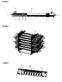
- FIG. 1 shows an ATS channel.
- Product flows in at the inlet (1) and through the channel (9) to the outlet (2).
- Heating or cooling fluid (where required) is pumped through the heating/cooling jacket (10) via inlet (3) and outlet (4) connections.
- a variety of cooling/heating jacket designs can be used.
- Free moving agitator elements of a different density to other fluid components are located within the channel.
- a spring shaped mixer (5) is shown.
- Figure 1 shows a series of separate mixers (5 and 7).
- a mixer ring (6) can be used as shown in Figure 1 .
- Optional expansion bellows for the heating/cooling jacket (8) are shown. These accommodate differential expansion between the shell and jacket.
- the channel or channels are mounted on a moving platform (not shown in Figure 1 ).
- the channel may also be connected to other channels to increase capacity as shown in Figure 2.
- Figure 2 shows multiple channels (11) such as that shown in Figure 1 mounted on an agitating platform (12) which moves the assembly to and fro in a direction transverse to the long axes of the channels.
- the direction of movement may also be orbital or some other pattern in a direction transverse to the long axes of the channels. Details of the platform agitating mechanism are not shown.
- the process channel may have a variety of connections at different points such as for instruments, sampling or addition.
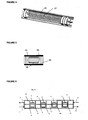
- FIG. 3 shows a spring shaped agitator (14) within the reaction channel (13).
- an optional agitator ring (15).
- Agitator rings (15) prevent the ends of adjacent agitators from clashing or binding. They can also provide a soft contact surface for the agitator elements when touching the sides of the channel. This can reduce wear and product damage.
- the agitator ring may have holes or cut outs to improve flow along the channel.
- the agitator ring may be made of a soft material like plastic or a hard material like metal. It may also use a rubber or plastic layers to cushion impact and generate recoil.
- the agitator ring can also be used to reduce back mixing or to trap one phase of fluid.
- the combined effect of the agitators is to sweep 50% or more of the channel diameter.
- agitators containing mixing elements of more than one diameter can be used as shown in figure 4 .
- This uses 4 outer mixing rods (16) and an inner rod (17).
- concentric rings or springs within springs can be used as mixers.
- Figure 5 shows a static agitator guide within a process channel (21).
- the agitator (18) has a hollow centre to permit free movement.
- the agitator guides (19) prevent adjacent agitators from touching.
- the agitator guide spacer (20) is a rod that connects the agitator guides.
- the long axes of the agitator guide spacers are within the middle 1/3 rd of the channel diameter. It can be located at the perimeter but this will reduce heat transfer capacity or can obstruct movement of the agitator.
- the agitator guides and the agitator guide spacers may be designed to be inserted by sliding in from one end of the tube.
- the agitator guides can be solid discs with holes in the centre or cut outs at the perimeter to allow the passage of process material along the channel. They can also be spider shaped guides.
- the agitator guides can also be used to control axial movement of a mixing element when this is a fluid or gas of different density. In these cases it is preferable that the agitator guides provide a solid ring at the outer perimeter to act as weirs to retain gases or denser materials. In these cases, process materials pass across the guide through holes which are not at the perimeter.
- the systems employ temperature control although systems without temperature control may also be used.
- an external cooling/heating jacket may be used in the form of an outer sleeve or coils.
- it may be an electrical heater.
- Temperature control may be achieved by means of a temperature sensor which monitors the temperature of the process fluid. The signal from the temperature sensor can be used to vary the flow rate or temperature of the heating or cooling medium where said medium is a heat transfer fluid or to vary electrical power in the case of an electrical heater. Different temperature control strategies can be employed as different points along the tube.
- the ATS uses dynamic mixing which is primarily in the radial plane; mixing efficiency is not dependent on linear velocity of fluid through the channel and plug flow is less dependent on linear velocity of the fluid through the channel compared to systems which do not use dynamic mixing in the radial plane. This means that, if required, different diameter channels can be used at different stages of the reactor (with substantially the same mixing and plug flow characteristics) to suit changing requirements such as heat transfer requirements.
- the direction of shaking is in the radial plane and the agitator movement may be rotational, transverse or a variety of trajectories within the radial plane. Where there is movement of the agitator in the axial plane, it is preferable that this is limited to less than 10% of the channel length.
- the frequency of shaking is linked to the level of mixing required.
- the average velocity of the agitator in the radial direction should be greater than the axial velocity of the process material travelling through the channel and preferably 5 times greater than the axial velocity and even more preferably 10 times greater than the axial velocity.
- the average velocity of the agitator can also be up to 50 times greater than the axial velocity of the process flow or higher (high mixing velocities are particularly important for mass transfer limited processes). For processes which require fast or efficient mixing, shaking speeds of between 1 and 10 cycles per second (or higher) can be used but mixing times of up to 100 cycles per second can be used.
- the diameter of the channel may be less than 1 mm or larger than 1 m.
- the constraint with small diameter channels however is that they use smaller agitators which result in increased surface drag per unit mass. This results in reduced mixing efficiency (especially with more viscous fluids).
- systems with channel diameters of greater than 100 mm diameter can be used, these are subject to increased cost and are more difficult to mix by shaking.
- the preferred channel diameter is therefore from 10 mm to 100 mm and more preferably 25 mm to 80 mm.
- the preferred capacity of a single channel is between 10 millilitres and 10 litres. More preferably, the capacity is between 100 millilitres and 1 litre.
- the length of the channel is at least 5 times the channel diameter and even more preferably at least 10 times the channel diameter.
- the agitating action can be applied to the whole system or individual channels.
- the agitation action can also be applied to banks of channels independently or several banks working in opposition. Any suitable method of agitation may be used.
- the channels may be mounted on a sliding frame or alternatively on bushes, bearings or springs to permit movement.
- the channel assembly can be shaken by a variety of means such as electrical motors, hydraulic power, electro magnets, or compressed gas.
- the process channels are preferably rigid so that the shaking energy can be transmitted efficiently to the channel contents.
- channel materials include (but are not limited to) metal, glass, plastic lined metal, ceramic, glass lined metal or plastic.
- the channels can be mounted vertically, horizontally or at a slope. The orientation of the channel will depend on the nature of process requirements.
- Agitators in a variety of materials of construction may be used.
- Agitator shapes include hollow cylinders, springs, hollow baskets (for holding catalyst or other solids).
- Within a single reactor channel there may be one agitator or many agitators.
- Solid agitators are used. It is generally preferable to employ external profiles which are round to promote a rolling action in the channel.
- the length of the agitators can be the same as the channel length. It is preferable however to use agitators which are less than 300 mm in length. This reduces the problem of unbalanced agitator movement (where the long axis of the agitator deviates from the long axis of the channel). Unbalanced agitator movement promotes axial mixing which is undesirable.
- Agitators may also be tethered to the channel to partially restrict their movement.
- the agitator elements may be provided with end caps to guide and control their movement within the channel.
- the channels are designed with no internal obstructions so that mixer elements (agitators) and spacers can be inserted and removed at one or either ends of the channels. This simplifies cleaning and assembly.
- the channels have removable end caps so that the tubes and internal elements can be accessed for inspection, cleaning or repair.
- Process fluid is delivered to the channels by means of a fluid transfer pump.
- Process fluid may also be delivered to the channels by gravity transfer or a supply vessel with a pressurised head space. Where the process fluid is a gas, this may be delivered to the channel from a pressurised container.
- the ATS can also be used for counter current processes such as extraction or counter current reactions.
- counter current processes such as extraction or counter current reactions.
- the light and heavy phases are added at opposite ends of the channels and also taken off at opposite ends to their respective inlet points.
- Figure 6 illustrates such a counter current system.
- Figure 6 shows a tube (22) mounted on an agitator platform (not shown) for mixing by shaking .
- the tube is provided with a first inlet (23) for a light phase material, a second inlet (24) for a heavy phase material.
- Outlet pipes (25) and (26) respectively for the light phase and the heavy phase.
- Agitator elements (27) are provided along the tube optionally provided with agitator guides (28) to provide separated zones (29) to aid separation of the heavy and light phases following their mixing and counter current extraction. Separating zones without mixing are required at the respective inlets points for the light and heavy phases. Additional separating zones may be used as shown or not in some cases.
- the ATS design can deliver efficient radial mixing at low (or fast) velocities.
- the advantage of this is flexibility and that good plug flow and good mixing can be achieved in much shorter channels (for a given volume) compared to statically mixed devices.
- the benefits of this design include:
- the advantages of flow systems over batch systems have been widely reported and include improved safety, improved yield, faster reaction rates and higher quality.
- the commercial benefits of the ATS design relate to the fact that it is a flow system which can handle a wide range of processes that would be impossible or prohibitively expensive in other types of flow systems. It is also substantially easier and cheaper to build than multi stage systems which use rotating stirrers.
- the ATS can be used as (but not limited to):
- ATS use of an ATS is illustrated by the following example involving the reaction for the oxidation of D-amino acid to give a mixture of L-amino acid and ⁇ -keto acid was carried out in the Agitated Tube Reactor (ATR). The results were compared to a 1 litre batch vessel with an agitation speed of 400 rpm. The reaction is multiphase with solids, gas and liquid involved. Oxygen is bubbled through the reaction mixture which contains the D-amino acid, non-immobilized enzymes on whole cells and the substrate alanine.
- Figure 7 shows the residence time (hours) against conversion (%) for the reaction carried out in a 1 litre ATR and a 1 litre batch vessel. In both reactors, the same amount of oxygen per unit volume was used.
- the results show that the ATR achieves a similar conversion to the batch reactor but completes the reaction in 9 hours as against 24 hours in the 1 litre batch reactor.
- the reaction rate is determined by the dissolution rate of oxygen in the liquid (mass transfer limited).
- the improved reaction time in the ATR can be attributed to improved mixing efficiency and hence faster mass transfer. This performance difference becomes even more significant with scale up. When a batch reactor is scaled up (by increaseding diameter and length), the mixing efficiency declines. When the ATR is scaled up (by increasing tube length) mixing efficiency remains unchanged.
- the graph shows that the ATR reaches a steady rate after 1.7 reactor volumes have been processed which is indicated by the constant conversion after this point.
- This steady conversion that is achieved indicates that the process fluid is being processed with a constant reaction time i.e. fluid moving through the reactor has a substantially uniform residence time This indicates orderly flow.
- Orderly flow is important for controlling reaction time and maximising reaction rate, yield and quality for many types of reaction.
- orderly flow relies on high velocities.
- the tube diameter was 42 mm.
- To maintain orderly flow in a tube of this diameter without dynamic mixing would require turbulent flow with a minimum linear velocity of 0.03 m/s.
- the ATR can maintain orderly flow at velocities of 0.00002 metres per second. The commercial implications of this result are substantial.
- the ATR is more flexible since its performance is not dependent on fluid velocity. It can also deliver good performance in short large diameter tubes with lower pressure drops. Both tube length and pressure drop have a major impact on cost.
- the ATS may be used for (but not limited to) scale up studies and manufacturing process in fine chemicals, foods, polymers, bulk chemicals, pharmaceuticals and minerals processing.
- the ATS delivers good plug flow and good mixing in short large tubes.
- these capabilities variously contribute to faster reaction times, smaller equipment, higher yields, higher purity, improved safety and the ability to handle reaction types that would not be possible in a large batch reactor.
Description
- This invention is concerned with a process and an apparatus for mixing according to
claims - Ideal plug flow refers to a flow condition where the velocity of a flowing fluid is uniform across the face of the channel and no back mixing occurs. It should be recognised however that ideal plug flow is neither desirable for larger tubes (some lateral movement in larger channels is necessary for mixing) nor possible (e.g. wall friction affects the velocity profile). In this document, plug flow refers to a condition which approximates to ideal plug flow. In this context, plug flow means orderly flow such that fluid elements travel through and leave a channel in substantially the same order that they enter the channel. It also applies to systems where two phases are travelling in opposite directions (counter current flow) but each phase approximately obeying the rules for plug flow in its respective direction (other than components which may transfer between phases). The invention therefore minimises the degree of back mixing of the material within the channels, furthermore the radial mixing can reduce the effect of stagnant zones or surface drag and in so doing improve the quality of plug flow.
- This invention relates to flow in channels. The term axial refers to the long axis of the channel. The net direction of fluid through the channel is axial. The term radial refers to the plane which is substantially at 90° to the axial axis.
- The term static mixing in this document refers to systems where the flow direction of fluid within a channel is changed without moving mixer elements. Examples include turbulent flow, channel bends, baffles and static mixers. This invention relates to dynamic mixing in flowing channels. Most conventional dynamic mixers involve the use of rotating stirrers. The mixing process of this invention is achieved by shaking the channel. The channel contains agitators to enhance mixing and in this instance the preferred agitator movement is limited to the radial plane.
- The term channel used in this patent describes the channel through which process material flows. It may be a tube or pipe. References to ratios such as channel diameter to length assume that the channel is circular. Where the channel is non circular, estimates of these or other parameters can be applied by reasonable judgement using the rationale and sizing criteria described herein.
- Channel in the context of this patent refers to a tube or pipe which is mixed by shaking. A series of channels may be employed in series in which case each channel may be separated from another channel by a connecting pipe. The diameter of any connecting pipe is preferably smaller than the channel so as to maintain orderly flow in the absence of dynamic mixing within the connecting pipe. A series of channels may also be employed in parallel.
- A system is referred to as an agitated tube system (ATS) or agitated tube reactor (ATR).
-
PCT Publication WO 2008/068019 describes an agitated cell reactor. It comprises two or more continuous stirred cells (CSTs) whereby mixing is achieved by shaking the cells. Providing materials of two different densities are present within the cells, the effect of shaking is to generate mixing. Fluid movement within individual stages within the agitated cell reactor do not follow a plug flow pattern. When multiple stages are used in series however, plug flow characteristics are achieved. The limitation of this design relates to scale up. In the agitated cell reactor, the fluid composition within a mixed cell must be substantially uniform to prevent bypassing or hold up. For this reason, the length of the cell should be similar to the diameter. This results in large diameter stages when the stage volumes are increased. Large diameter stages are less efficient than small diameter channels as they require greater shaker travel (which limits shaking frequency). Large diameter channels also increase weight and height of the system which affects stability and requires greater shaker power. - The present invention concerns a tubular system which uses a shaking mixing technique. Unlike
WO 2008/068019 , this is a tubular system which does not require multiple stages for plug flow (although stage separation may be used for reasons of compactness). In this design, channel length (not multiple discrete stages) forms the basis for maintaining plug flow of product through the channel. The inlet and outlet to the channel in this design are separated by the furthest practical distance on the axial path. The agitated tube system has the following benefits. - The preferred direction of mixing in the ATS is in the radial plane whereas the direction of mixing in the agitated cell reactor is preferably random. This means that the flow pattern within a single stage within the ATS is substantially plug flow. This results in plug flow through a single channel.
- The position of the inlet pipe in relation to the outlet pipe is immaterial in an ideal agitated cell reactor. In the ATS, the inlet and outlet pipes are separated by the maximum practical distance on the axial plane.
- In the agitated cell design, the composition of material in the discharge pipe is substantially the same as any point in the cell. In the ATS, the composition of material in the discharge pipe is only the same as material within the ATS channel which is in immediate proximity to the discharge pipe.
- United States Patent
5628562 describes a dosing apparatus comprising a tube which can be fed with two materials and can be moved from left to right to cause mixing. Wires are attached to the inner walls of the tube and extend longitudinally through the tube to enhance the mixing. Although no dimensions are quoted, the design is not a plug flow system and the mixing elements as shown are specifically aimed to promote mixing in both the axial and radial planes. -
JP 2004-195 384 claim - The ATS design permits the use of long channels and it also can permit to the use of channels with comparatively small diameters. Long small diameter tubes contribute to lower weight, lower build cost, and inherently better mixing characteristics than the agitated cell design for capacities over 200 millilitres. ATS systems of less than 200 millilitres can also be used. ATS systems of less than 200 millilitres can also be used. Depending upon the use to which the ATS is to be put, it may be convenient to provide it with a temperature control jacket. This provides the means to regulate the process temperature and add or remove heat where required.
- One or more of the channels of the ATS is mounted on a shaking platform and mixing is generated by shaking the channels. As with the agitated cell design, materials of more than one density must be present within the channel for mixing to occur. The design is illustrated by reference to the accompanying Figures.
Figure 1 shows an ATS channel. Product flows in at the inlet (1) and through the channel (9) to the outlet (2). Heating or cooling fluid (where required) is pumped through the heating/cooling jacket (10) via inlet (3) and outlet (4) connections. A variety of cooling/heating jacket designs can be used. Free moving agitator elements of a different density to other fluid components are located within the channel. In this example, a spring shaped mixer (5) is shown.Figure 1 shows a series of separate mixers (5 and 7). Alternatively, different kinds of mixers can be used in a single channel. A mixer ring (6) can be used as shown inFigure 1 . Optional expansion bellows for the heating/cooling jacket (8) are shown. These accommodate differential expansion between the shell and jacket. The channel or channels are mounted on a moving platform (not shown inFigure 1 ). The channel may also be connected to other channels to increase capacity as shown inFigure 2. Figure 2 shows multiple channels (11) such as that shown inFigure 1 mounted on an agitating platform (12) which moves the assembly to and fro in a direction transverse to the long axes of the channels. The direction of movement may also be orbital or some other pattern in a direction transverse to the long axes of the channels. Details of the platform agitating mechanism are not shown. The process channel may have a variety of connections at different points such as for instruments, sampling or addition. -
Figure 3 shows a spring shaped agitator (14) within the reaction channel (13). At each end of the agitator is an optional agitator ring (15). Agitator rings (15) prevent the ends of adjacent agitators from clashing or binding. They can also provide a soft contact surface for the agitator elements when touching the sides of the channel. This can reduce wear and product damage. The agitator ring may have holes or cut outs to improve flow along the channel. The agitator ring may be made of a soft material like plastic or a hard material like metal. It may also use a rubber or plastic layers to cushion impact and generate recoil. The agitator ring can also be used to reduce back mixing or to trap one phase of fluid. - It is preferable that the combined effect of the agitators is to sweep 50% or more of the channel diameter. To achieve this, agitators containing mixing elements of more than one diameter can be used as shown in
figure 4 . This uses 4 outer mixing rods (16) and an inner rod (17). Alternatively concentric rings or springs within springs can be used as mixers.Figure 5 shows a static agitator guide within a process channel (21). The agitator (18) has a hollow centre to permit free movement. The agitator guides (19) prevent adjacent agitators from touching. The agitator guide spacer (20) is a rod that connects the agitator guides. So as to permit the free movement of the agitator, it is preferable that the long axes of the agitator guide spacers are within the middle 1/3rd of the channel diameter. It can be located at the perimeter but this will reduce heat transfer capacity or can obstruct movement of the agitator. The agitator guides and the agitator guide spacers may be designed to be inserted by sliding in from one end of the tube. The agitator guides can be solid discs with holes in the centre or cut outs at the perimeter to allow the passage of process material along the channel. They can also be spider shaped guides. The agitator guides can also be used to control axial movement of a mixing element when this is a fluid or gas of different density. In these cases it is preferable that the agitator guides provide a solid ring at the outer perimeter to act as weirs to retain gases or denser materials. In these cases, process materials pass across the guide through holes which are not at the perimeter. - In a further embodiment the systems employ temperature control although systems without temperature control may also be used. Where temperature control is employed, an external cooling/heating jacket may be used in the form of an outer sleeve or coils. Alternatively it may be an electrical heater. Temperature control may be achieved by means of a temperature sensor which monitors the temperature of the process fluid. The signal from the temperature sensor can be used to vary the flow rate or temperature of the heating or cooling medium where said medium is a heat transfer fluid or to vary electrical power in the case of an electrical heater. Different temperature control strategies can be employed as different points along the tube.
- Because the ATS uses dynamic mixing which is primarily in the radial plane; mixing efficiency is not dependent on linear velocity of fluid through the channel and plug flow is less dependent on linear velocity of the fluid through the channel compared to systems which do not use dynamic mixing in the radial plane. This means that, if required, different diameter channels can be used at different stages of the reactor (with substantially the same mixing and plug flow characteristics) to suit changing requirements such as heat transfer requirements.
- The direction of shaking is in the radial plane and the agitator movement may be rotational, transverse or a variety of trajectories within the radial plane. Where there is movement of the agitator in the axial plane, it is preferable that this is limited to less than 10% of the channel length.
- The frequency of shaking is linked to the level of mixing required. As a minimum however, the average velocity of the agitator in the radial direction should be greater than the axial velocity of the process material travelling through the channel and preferably 5 times greater than the axial velocity and even more preferably 10 times greater than the axial velocity. The average velocity of the agitator can also be up to 50 times greater than the axial velocity of the process flow or higher (high mixing velocities are particularly important for mass transfer limited processes). For processes which require fast or efficient mixing, shaking speeds of between 1 and 10 cycles per second (or higher) can be used but mixing times of up to 100 cycles per second can be used.
- The diameter of the channel may be less than 1 mm or larger than 1 m. The constraint with small diameter channels however is that they use smaller agitators which result in increased surface drag per unit mass. This results in reduced mixing efficiency (especially with more viscous fluids). Although systems with channel diameters of greater than 100 mm diameter can be used, these are subject to increased cost and are more difficult to mix by shaking. The preferred channel diameter is therefore from 10 mm to 100 mm and more preferably 25 mm to 80 mm.
- Increasing the length of the reactor channel increases volumetric capacity. There is no limit to the length that can be used. However, for practical reasons, channel lengths of 2 metres or less are preferred since they have to be mounted on a shaking platform (where rigidity is desirable for good transmission of shaking energy). Where longer channels are necessary, it is preferable to break the channel up into a series of shorter channels of 2 metres or less in length and more preferably 1 metre or less in length. Where multiple channels are used, these are preferably linked by channels with reduced diameter (to ensure good plug flow and minimum transfer delay between mixed channels ). We have found that the use of a system according to the present invention enables the use of substantially shorter and larger diameter channels than with previous tubular continuous flow systems
- The preferred capacity of a single channel is between 10 millilitres and 10 litres. More preferably, the capacity is between 100 millilitres and 1 litre.
- To maintain plug flow, the length of the channel is at least 5 times the channel diameter and even more preferably at least 10 times the channel diameter.
- The agitating action can be applied to the whole system or individual channels. The agitation action can also be applied to banks of channels independently or several banks working in opposition. Any suitable method of agitation may be used. The channels may be mounted on a sliding frame or alternatively on bushes, bearings or springs to permit movement. The channel assembly can be shaken by a variety of means such as electrical motors, hydraulic power, electro magnets, or compressed gas.
- The process channels are preferably rigid so that the shaking energy can be transmitted efficiently to the channel contents. Examples of channel materials include (but are not limited to) metal, glass, plastic lined metal, ceramic, glass lined metal or plastic. The channels can be mounted vertically, horizontally or at a slope. The orientation of the channel will depend on the nature of process requirements.
- Agitators in a variety of materials of construction may be used. Agitator shapes include hollow cylinders, springs, hollow baskets (for holding catalyst or other solids). Within a single reactor channel there may be one agitator or many agitators. Solid agitators are used. It is generally preferable to employ external profiles which are round to promote a rolling action in the channel. The length of the agitators can be the same as the channel length. It is preferable however to use agitators which are less than 300 mm in length. This reduces the problem of unbalanced agitator movement (where the long axis of the agitator deviates from the long axis of the channel). Unbalanced agitator movement promotes axial mixing which is undesirable. Agitators may also be tethered to the channel to partially restrict their movement. The agitator elements may be provided with end caps to guide and control their movement within the channel.
- It is preferred that the channels are designed with no internal obstructions so that mixer elements (agitators) and spacers can be inserted and removed at one or either ends of the channels. This simplifies cleaning and assembly.
- It is preferred that the channels have removable end caps so that the tubes and internal elements can be accessed for inspection, cleaning or repair.
- Process fluid is delivered to the channels by means of a fluid transfer pump. Process fluid may also be delivered to the channels by gravity transfer or a supply vessel with a pressurised head space. Where the process fluid is a gas, this may be delivered to the channel from a pressurised container.
- The ATS can also be used for counter current processes such as extraction or counter current reactions. In counter current flow, it is desirable (and usually necessary) to have unmixed zones to allow for the separation of the light and heavy phases. The light and heavy phases are added at opposite ends of the channels and also taken off at opposite ends to their respective inlet points.
-
Figure 6 illustrates such a counter current system. -
Figure 6 shows a tube (22) mounted on an agitator platform (not shown) for mixing by shaking . The tube is provided with a first inlet (23) for a light phase material, a second inlet (24) for a heavy phase material. Outlet pipes (25) and (26) respectively for the light phase and the heavy phase. Agitator elements (27) are provided along the tube optionally provided with agitator guides (28) to provide separated zones (29) to aid separation of the heavy and light phases following their mixing and counter current extraction. Separating zones without mixing are required at the respective inlets points for the light and heavy phases. Additional separating zones may be used as shown or not in some cases. - The ATS design can deliver efficient radial mixing at low (or fast) velocities. The advantage of this is flexibility and that good plug flow and good mixing can be achieved in much shorter channels (for a given volume) compared to statically mixed devices. The benefits of this design include:
- 1. Significantly improved mixing for a given axial velocity when compared to statically mixed devices.
- 2. High volumetric capacity in short channels and therefore significantly lower build cost compared to statically mixed systems. For example, 1 litre of reactor capacity in a statically mixed channel of 1 mm diameter would require over 1200 metres of pipe. In the case of a statically mixed reactor, a 40 mm channel of 1 metre would only achieve fast mixing and good plug flow at high flow rates with very short residence times. A 1 litre system of this invention with channel length of 1 metre length and with a channel diameter of 40 mm can deliver good mixing and good plug flow for reaction times from seconds to many hours.
- 3. Short channels with large diameters of this design have a low pressure drop by virtue of low axial velocity and large channel diameter. They also have good solids handling characteristics by virtue of good mixing and large channel diameters.
- 4. Systems of this design are inherently simpler to scale up as mixing is less dependent on channel length, channel diameter or fluid velocity when compared with statically mixed systems. The high ratio of radial mixing to axial mixing ensures greater consistency of plug flow during scale up.
- Compared to rotational mixers in conventional stirred tank designs, the advantages of this type of mixing are:
- 1. No wetted drive shafts or magnetic couplings are required to generate movement of the agitator.
- 2. No mechanical seals are required
- 3. The agitator elements can move in a transverse action (as opposed to rotational) which is effectively self baffling. This is an efficient mixing method which eliminates the need for baffles (which are difficult to install in channels where agitator drive shafts are present).
- 4. Good scale up characteristics. Mixing and plug flow are substantially unaffected by scale up, and pressure drop reduces with scale up.
- The advantages of flow systems over batch systems have been widely reported and include improved safety, improved yield, faster reaction rates and higher quality. The commercial benefits of the ATS design relate to the fact that it is a flow system which can handle a wide range of processes that would be impossible or prohibitively expensive in other types of flow systems. It is also substantially easier and cheaper to build than multi stage systems which use rotating stirrers.
- The ATS can be used as (but not limited to):
- Continuous chemical reactors for chemical reactions with homogenous fluids, chemical reactions with slurries, chemical reactions with gas/liquid mixtures, chemical reactions with immiscible liquids, chemical reactions with solid catalysts, chemical reactions with immobilised solid catalyst, counter current chemical reactions and mixtures of these. It is also ideal for reaction times of greater than 30 seconds.
- Continuous bio reactors for bio catalysis with live or dead cells, enzyme treatment processes and growth of live cells
- Continuous flow systems for mixing or fluid transfer including homogenous and non homogenous fluids.
- Continuous flow systems for co current extraction, counter current extraction, crystallisation, dissolving gases or solids or super critical processes
- The use of an ATS is illustrated by the following example involving the reaction for the oxidation of D-amino acid to give a mixture of L-amino acid and α-keto acid was carried out in the Agitated Tube Reactor (ATR). The results were compared to a 1 litre batch vessel with an agitation speed of 400 rpm. The reaction is multiphase with solids, gas and liquid involved. Oxygen is bubbled through the reaction mixture which contains the D-amino acid, non-immobilized enzymes on whole cells and the substrate alanine.
-
Figure 7 below shows the residence time (hours) against conversion (%) for the reaction carried out in a 1 litre ATR and a 1 litre batch vessel. In both reactors, the same amount of oxygen per unit volume was used. - The results show that the ATR achieves a similar conversion to the batch reactor but completes the reaction in 9 hours as against 24 hours in the 1 litre batch reactor. The reaction rate is determined by the dissolution rate of oxygen in the liquid (mass transfer limited). The improved reaction time in the ATR can be attributed to improved mixing efficiency and hence faster mass transfer. This performance difference becomes even more significant with scale up. When a batch reactor is scaled up (by increaseding diameter and length), the mixing efficiency declines. When the ATR is scaled up (by increasing tube length) mixing efficiency remains unchanged.
- These results illustrate the benefits of efficient mixing for accelerated reaction rate. Good mixing is not only important for mass transfer limited reactions however, it is also important for orderly flow.
Figure 8 below shows the number of reactor volumes processed by theATR 1 litre vessel against the conversion achieved. This test was performed to assess the orderly flow capabilities of the ATR. - The graph shows that the ATR reaches a steady rate after 1.7 reactor volumes have been processed which is indicated by the constant conversion after this point. This steady conversion that is achieved indicates that the process fluid is being processed with a constant reaction time i.e. fluid moving through the reactor has a substantially uniform residence time This indicates orderly flow.
- Orderly flow is important for controlling reaction time and maximising reaction rate, yield and quality for many types of reaction. In a conventional tubular reactor orderly flow relies on high velocities. In this experiment, the tube diameter was 42 mm. To maintain orderly flow in a tube of this diameter without dynamic mixing would require turbulent flow with a minimum linear velocity of 0.03 m/s. As these results illustrate, the ATR can maintain orderly flow at velocities of 0.00002 metres per second. The commercial implications of this result are substantial. The ATR is more flexible since its performance is not dependent on fluid velocity. It can also deliver good performance in short large diameter tubes with lower pressure drops. Both tube length and pressure drop have a major impact on cost.
- The ATS may be used for (but not limited to) scale up studies and manufacturing process in fine chemicals, foods, polymers, bulk chemicals, pharmaceuticals and minerals processing.
- The ATS delivers good plug flow and good mixing in short large tubes. Depending on reaction type, these capabilities variously contribute to faster reaction times, smaller equipment, higher yields, higher purity, improved safety and the ability to handle reaction types that would not be possible in a large batch reactor.
Claims (14)
- A process for mixing a stream of a fluid continuously flowing in a channel (9) having a ratio of length to diameter greater than 5 containing one or more loose agitating elements which are of a different density to other material in the channel and said channel has one or more inlets (1) for material and one or more outlets (2) for material and material passing through the channel is subject to orderly flow and movement of the one or more agitating elements (5, 14) is generated by shaking the channel whereby the direction of mixing is substantially transverse to the direction of material flow through the channel, characterized in the one or more agitating elements comprising a hollow cylinder, a spring or a hollow basket (5, 14).
- A process according to Claim 1 wherein the direction of movement of the one or more agitating elements (5), (14) is limited to the radial plane.
- A process according to Claim 1 or Claim 2 wherein the channel (9) comprises one or more tubes (11) mounted on a shaking platform (12) and mixing is generated by shaking the tube(s).
- A process according to any of the preceding claims wherein the shaking speed of the agitation is between 1 and 100 cycles per second.
- A process according to any of the preceding claims wherein the channel diameter is from 10 mm to 100 mm.
- A process according to any of the preceding claims comprising chemical, biological or physical reactions or combinations thereof.
- A process according to any of the preceding claims wherein the average velocity of the one or more, agitating element in the radial direction is 5 times greater than the axial velocity of the process material travelling through the channel.
- An apparatus for mixing a continuously orderly flowing stream comprising a channel (9) containing one or more agitating elements (5, 14) which are of a different density to other material in the channel and said channel has one or more inlets (1) for material and one or more outlets (2) for material, a means for shaking the channel and to generate movement of the one or more agitating elements (5, 14) whereby the direction of mixing due to the movement of the one or more agitating elements is primarily in the radial plane substantially transverse to the direction of material flow through the channel wherein the channel has a ratio of length to diameter greater than 5 characterized in that the one or more agitating comprise a hollow cylinder, a spring or a hollow basket.
- An apparatus according to Claim 8 which uses agitator rings (15).
- An apparatus according to Claim 8 or Claim 9 wherein the direction of movement of the one or more agitating elements (5, 14) is limited to the radial plane.
- An apparatus according to any of Claims 8 to 10 that uses agitator guide spacers (20).
- An apparatus according to any of Claims 8 to 11 wherein the channel (9) comprises one or more tubes (11) mounted on a shaking platform (12) and mixing is generated by shaking the tube(s).
- An apparatus according to any of Claims 8 to 12 wherein the agitating element comprises a loose solid mechanical part.
- An apparatus according to any of Claims 8 to 13 wherein the channel diameter is from 10 mm to 100 mm.
Applications Claiming Priority (2)
| Application Number | Priority Date | Filing Date | Title |
|---|---|---|---|
| GBGB1005742.0A GB201005742D0 (en) | 2010-04-06 | 2010-04-06 | Improved tubular reactor |
| PCT/EP2011/001702 WO2011124365A1 (en) | 2010-04-06 | 2011-04-06 | Improved tubular reactor and process |
Publications (2)
| Publication Number | Publication Date |
|---|---|
| EP2555861A1 EP2555861A1 (en) | 2013-02-13 |
| EP2555861B1 true EP2555861B1 (en) | 2015-12-30 |
Family
ID=42228942
Family Applications (1)
| Application Number | Title | Priority Date | Filing Date |
|---|---|---|---|
| EP11717477.1A Active EP2555861B1 (en) | 2010-04-06 | 2011-04-06 | Improved tubular apparatus and process |
Country Status (7)
| Country | Link |
|---|---|
| US (1) | US9956533B2 (en) |
| EP (1) | EP2555861B1 (en) |
| JP (2) | JP2013523440A (en) |
| CN (2) | CN102905781A (en) |
| BR (1) | BR112012025544A8 (en) |
| GB (1) | GB201005742D0 (en) |
| WO (1) | WO2011124365A1 (en) |
Families Citing this family (12)
| Publication number | Priority date | Publication date | Assignee | Title |
|---|---|---|---|---|
| GB2507488A (en) * | 2012-10-30 | 2014-05-07 | Ashe Morris Ltd | Rotating flow reactor with extended flow path |
| GB2507487A (en) * | 2012-10-30 | 2014-05-07 | Ashe Morris Ltd | Rotating flow reactor |
| CN105569891A (en) * | 2014-10-16 | 2016-05-11 | 天津布尔科技有限公司 | Methyl alcohol and gasoline on-line mixed oil supply system |
| USD787085S1 (en) | 2015-02-27 | 2017-05-16 | Heathrow Scientific Llc | Head for a mixing apparatus |
| US9895670B2 (en) | 2015-02-27 | 2018-02-20 | Heathrow Scientific Llc | Head for a mixing apparatus |
| CN104667848B (en) * | 2015-03-12 | 2017-04-05 | 西安科技大学 | A kind of equipment of industrial product of composite Nano anti-attrition coating |
| JP6300339B1 (en) * | 2018-01-04 | 2018-03-28 | Cpmホールディング株式会社 | Liquefaction accelerating device having a vibration and swingable spring |
| WO2020097114A1 (en) * | 2018-11-06 | 2020-05-14 | Deep Science, Llc | Systems and methods for active control of surface drag using wall coupling |
| CN110841587A (en) * | 2019-12-16 | 2020-02-28 | 山东豪迈机械制造有限公司 | Reaction device and reaction equipment |
| CN112090388B (en) * | 2020-09-07 | 2022-04-12 | 浙江大学 | Continuous flow reactor and application thereof in chemical reaction and synthesis |
| CN112569892B (en) * | 2020-12-31 | 2022-08-02 | 驻马店恒瑞高温节能材料有限公司 | Energy-conserving material raw materials reation kettle of high temperature convenient to wash |
| GB2603456A (en) * | 2021-01-07 | 2022-08-10 | Ashe Robert | Improved method and apparatus plug flow system |
Family Cites Families (28)
| Publication number | Priority date | Publication date | Assignee | Title |
|---|---|---|---|---|
| DE236257C (en) * | ||||
| DE1034153B (en) * | 1956-12-12 | 1958-07-17 | Basf Ag | Process for carrying out continuous chemical reactions |
| DE1208606B (en) * | 1960-11-22 | 1966-01-05 | Draiswerke Ges Mit Beschraenkt | Vibrating mill |
| US4074363A (en) * | 1976-09-17 | 1978-02-14 | Ric-Wil, Incorporated | Apparatus for generating plastic foam |
| US4812046A (en) * | 1985-10-04 | 1989-03-14 | Carl Henderickson | Device for mixing two materials |
| ATE179093T1 (en) | 1995-03-22 | 1999-05-15 | Octal Technologies Ch Krumm | MIXER FOR MULTI-COMPONENT PRODUCTS WITH REPLACEABLE CARTRIDGE |
| AU3857597A (en) | 1996-08-09 | 1998-03-06 | Genex Limited | Agitation apparatus |
| JPH10286479A (en) | 1997-04-14 | 1998-10-27 | Nkk Corp | Sample pulverizing device and pulverizing method |
| US6357907B1 (en) | 1999-06-15 | 2002-03-19 | V & P Scientific, Inc. | Magnetic levitation stirring devices and machines for mixing in vessels |
| EP1439910A2 (en) | 2001-07-26 | 2004-07-28 | Motorola, Inc. | System and methods for mixing within a microfluidic device |
| US7192560B2 (en) | 2001-12-20 | 2007-03-20 | 3M Innovative Properties Company | Methods and devices for removal of organic molecules from biological mixtures using anion exchange |
| JP2004195384A (en) * | 2002-12-19 | 2004-07-15 | Kubota Matsushitadenko Exterior Works Ltd | Grinding method of material to be ground in liquid |
| US20040161511A1 (en) * | 2003-02-14 | 2004-08-19 | Mars Incorporated | Grinding and mixing edible fat-based slurries and emulsions using a vibratory media mill |
| EP1729136B1 (en) | 2004-03-23 | 2012-02-22 | Toray Industries, Inc. | Method of agitating solution |
| WO2005100980A2 (en) | 2004-04-06 | 2005-10-27 | Bio/Data Corporation | Disposable test device with sample volume measurement and mixing methods |
| WO2005121310A2 (en) | 2004-06-07 | 2005-12-22 | Bioprocessors Corp. | Creation of shear in a reactor |
| BE1016381A3 (en) * | 2004-12-15 | 2006-10-03 | Broqueville Axel De | DEVICE AND METHOD FOR ROTATING FLUIDIZED BED ROOMS IN A CYLINDRICAL succesion. |
| JP4252993B2 (en) | 2005-05-12 | 2009-04-08 | 株式会社荏原製作所 | Mixer and reactor |
| GB0509742D0 (en) | 2005-05-13 | 2005-06-22 | Ashe Morris Ltd | Variable heat flux heat exchangers |
| GB0509746D0 (en) | 2005-05-13 | 2005-06-22 | Ashe Morris Ltd | Variable plate heat exchangers |
| GB0509747D0 (en) | 2005-05-13 | 2005-06-22 | Ashe Morris Ltd | Variable volume heat exchangers |
| US7501482B2 (en) * | 2006-05-24 | 2009-03-10 | Eastman Chemical Company | Crystallizer temperature control via solid additive control |
| GB0614810D0 (en) * | 2006-07-25 | 2006-09-06 | Nitech Solutions Ltd | Improved apparatus and method for maintaining consistently mixed materials |
| JP2008043892A (en) * | 2006-08-18 | 2008-02-28 | Ebara Corp | Mixer and reactor |
| ATE552904T1 (en) | 2006-12-06 | 2012-04-15 | Ashe Morris Ltd | FLOW REACTOR |
| GB0624374D0 (en) * | 2006-12-06 | 2007-01-17 | Ashe Morris Ltd | Improved flow reactor |
| JP4785941B2 (en) * | 2009-02-23 | 2011-10-05 | 富士フイルム株式会社 | Method for promoting fluid mixing reaction of microdevice and microdevice |
| US8960486B2 (en) * | 2010-06-16 | 2015-02-24 | Life Technologies Corporation | Fluid mixing system with hangers |
-
2010
- 2010-04-06 GB GBGB1005742.0A patent/GB201005742D0/en not_active Ceased
-
2011
- 2011-04-06 CN CN2011800251150A patent/CN102905781A/en active Pending
- 2011-04-06 JP JP2013503031A patent/JP2013523440A/en active Pending
- 2011-04-06 EP EP11717477.1A patent/EP2555861B1/en active Active
- 2011-04-06 WO PCT/EP2011/001702 patent/WO2011124365A1/en active Application Filing
- 2011-04-06 BR BR112012025544A patent/BR112012025544A8/en not_active IP Right Cessation
- 2011-04-06 CN CN201711103583.0A patent/CN107875949A/en active Pending
- 2011-04-06 US US13/639,342 patent/US9956533B2/en active Active
-
2016
- 2016-08-04 JP JP2016153510A patent/JP6940932B2/en active Active
Also Published As
| Publication number | Publication date |
|---|---|
| BR112012025544A2 (en) | 2016-06-28 |
| US20130044559A1 (en) | 2013-02-21 |
| JP2013523440A (en) | 2013-06-17 |
| WO2011124365A1 (en) | 2011-10-13 |
| CN102905781A (en) | 2013-01-30 |
| US9956533B2 (en) | 2018-05-01 |
| CN107875949A (en) | 2018-04-06 |
| JP6940932B2 (en) | 2021-09-29 |
| GB201005742D0 (en) | 2010-05-19 |
| JP2016198768A (en) | 2016-12-01 |
| BR112012025544A8 (en) | 2018-06-26 |
| EP2555861A1 (en) | 2013-02-13 |
Similar Documents
| Publication | Publication Date | Title |
|---|---|---|
| EP2555861B1 (en) | Improved tubular apparatus and process | |
| US10632449B2 (en) | Method of mixing using an improved flow reactor | |
| KR101187181B1 (en) | Stirring device and process for carrying out a gas-liquid reaction | |
| WO2006083250A1 (en) | Continuous segmented plug flow reactor | |
| JP6430543B2 (en) | Reaction chamber for chemical reactor and chemical reactor composed thereof | |
| EP3057694B1 (en) | Apparatus for mixing based on oscillatory flow reactors provided with smooth periodic constrictions | |
| JP5466009B2 (en) | Improved flow reactor | |
| GB2475401A (en) | Agitated cell reactors | |
| JP2019504765A (en) | Rotary tube mixer and mixing method | |
| CN101626824A (en) | Improved flow reactor | |
| JP2023073454A (en) | Continuous stirring device | |
| WO2006083251A1 (en) | Method for performing chemical reactions in a continuous segmented plug flow reactor | |
| CN111295240A (en) | Improved mixer for flow systems | |
| US20230149888A1 (en) | Tubular reactor with mixing means | |
| GB2602728A (en) | Improved method and apparatus plug flow system | |
| WO2014068013A2 (en) | Flow reactor with extended flow path |
Legal Events
| Date | Code | Title | Description |
|---|---|---|---|
| PUAI | Public reference made under article 153(3) epc to a published international application that has entered the european phase |
Free format text: ORIGINAL CODE: 0009012 |
|
| 17P | Request for examination filed |
Effective date: 20121106 |
|
| AK | Designated contracting states |
Kind code of ref document: A1 Designated state(s): AL AT BE BG CH CY CZ DE DK EE ES FI FR GB GR HR HU IE IS IT LI LT LU LV MC MK MT NL NO PL PT RO RS SE SI SK SM TR |
|
| DAX | Request for extension of the european patent (deleted) | ||
| 17Q | First examination report despatched |
Effective date: 20131010 |
|
| GRAP | Despatch of communication of intention to grant a patent |
Free format text: ORIGINAL CODE: EPIDOSNIGR1 |
|
| INTG | Intention to grant announced |
Effective date: 20150715 |
|
| GRAS | Grant fee paid |
Free format text: ORIGINAL CODE: EPIDOSNIGR3 |
|
| GRAA | (expected) grant |
Free format text: ORIGINAL CODE: 0009210 |
|
| AK | Designated contracting states |
Kind code of ref document: B1 Designated state(s): AL AT BE BG CH CY CZ DE DK EE ES FI FR GB GR HR HU IE IS IT LI LT LU LV MC MK MT NL NO PL PT RO RS SE SI SK SM TR |
|
| REG | Reference to a national code |
Ref country code: GB Ref legal event code: FG4D |
|
| REG | Reference to a national code |
Ref country code: CH Ref legal event code: EP |
|
| REG | Reference to a national code |
Ref country code: AT Ref legal event code: REF Ref document number: 767199 Country of ref document: AT Kind code of ref document: T Effective date: 20160115 |
|
| REG | Reference to a national code |
Ref country code: IE Ref legal event code: FG4D |
|
| REG | Reference to a national code |
Ref country code: DE Ref legal event code: R096 Ref document number: 602011022251 Country of ref document: DE |
|
| REG | Reference to a national code |
Ref country code: FR Ref legal event code: PLFP Year of fee payment: 6 |
|
| REG | Reference to a national code |
Ref country code: NL Ref legal event code: FP |
|
| REG | Reference to a national code |
Ref country code: LT Ref legal event code: MG4D |
|
| PG25 | Lapsed in a contracting state [announced via postgrant information from national office to epo] |
Ref country code: NO Free format text: LAPSE BECAUSE OF FAILURE TO SUBMIT A TRANSLATION OF THE DESCRIPTION OR TO PAY THE FEE WITHIN THE PRESCRIBED TIME-LIMIT Effective date: 20160330 Ref country code: HR Free format text: LAPSE BECAUSE OF FAILURE TO SUBMIT A TRANSLATION OF THE DESCRIPTION OR TO PAY THE FEE WITHIN THE PRESCRIBED TIME-LIMIT Effective date: 20151230 Ref country code: LT Free format text: LAPSE BECAUSE OF FAILURE TO SUBMIT A TRANSLATION OF THE DESCRIPTION OR TO PAY THE FEE WITHIN THE PRESCRIBED TIME-LIMIT Effective date: 20151230 |
|
| REG | Reference to a national code |
Ref country code: AT Ref legal event code: MK05 Ref document number: 767199 Country of ref document: AT Kind code of ref document: T Effective date: 20151230 |
|
| PG25 | Lapsed in a contracting state [announced via postgrant information from national office to epo] |
Ref country code: GR Free format text: LAPSE BECAUSE OF FAILURE TO SUBMIT A TRANSLATION OF THE DESCRIPTION OR TO PAY THE FEE WITHIN THE PRESCRIBED TIME-LIMIT Effective date: 20160331 Ref country code: FI Free format text: LAPSE BECAUSE OF FAILURE TO SUBMIT A TRANSLATION OF THE DESCRIPTION OR TO PAY THE FEE WITHIN THE PRESCRIBED TIME-LIMIT Effective date: 20151230 Ref country code: LV Free format text: LAPSE BECAUSE OF FAILURE TO SUBMIT A TRANSLATION OF THE DESCRIPTION OR TO PAY THE FEE WITHIN THE PRESCRIBED TIME-LIMIT Effective date: 20151230 Ref country code: SE Free format text: LAPSE BECAUSE OF FAILURE TO SUBMIT A TRANSLATION OF THE DESCRIPTION OR TO PAY THE FEE WITHIN THE PRESCRIBED TIME-LIMIT Effective date: 20151230 Ref country code: RS Free format text: LAPSE BECAUSE OF FAILURE TO SUBMIT A TRANSLATION OF THE DESCRIPTION OR TO PAY THE FEE WITHIN THE PRESCRIBED TIME-LIMIT Effective date: 20151230 |
|
| PG25 | Lapsed in a contracting state [announced via postgrant information from national office to epo] |
Ref country code: CZ Free format text: LAPSE BECAUSE OF FAILURE TO SUBMIT A TRANSLATION OF THE DESCRIPTION OR TO PAY THE FEE WITHIN THE PRESCRIBED TIME-LIMIT Effective date: 20151230 Ref country code: ES Free format text: LAPSE BECAUSE OF FAILURE TO SUBMIT A TRANSLATION OF THE DESCRIPTION OR TO PAY THE FEE WITHIN THE PRESCRIBED TIME-LIMIT Effective date: 20151230 |
|
| PG25 | Lapsed in a contracting state [announced via postgrant information from national office to epo] |
Ref country code: SK Free format text: LAPSE BECAUSE OF FAILURE TO SUBMIT A TRANSLATION OF THE DESCRIPTION OR TO PAY THE FEE WITHIN THE PRESCRIBED TIME-LIMIT Effective date: 20151230 Ref country code: PL Free format text: LAPSE BECAUSE OF FAILURE TO SUBMIT A TRANSLATION OF THE DESCRIPTION OR TO PAY THE FEE WITHIN THE PRESCRIBED TIME-LIMIT Effective date: 20151230 Ref country code: IS Free format text: LAPSE BECAUSE OF FAILURE TO SUBMIT A TRANSLATION OF THE DESCRIPTION OR TO PAY THE FEE WITHIN THE PRESCRIBED TIME-LIMIT Effective date: 20160430 Ref country code: RO Free format text: LAPSE BECAUSE OF FAILURE TO SUBMIT A TRANSLATION OF THE DESCRIPTION OR TO PAY THE FEE WITHIN THE PRESCRIBED TIME-LIMIT Effective date: 20151230 Ref country code: SM Free format text: LAPSE BECAUSE OF FAILURE TO SUBMIT A TRANSLATION OF THE DESCRIPTION OR TO PAY THE FEE WITHIN THE PRESCRIBED TIME-LIMIT Effective date: 20151230 Ref country code: AT Free format text: LAPSE BECAUSE OF FAILURE TO SUBMIT A TRANSLATION OF THE DESCRIPTION OR TO PAY THE FEE WITHIN THE PRESCRIBED TIME-LIMIT Effective date: 20151230 Ref country code: PT Free format text: LAPSE BECAUSE OF FAILURE TO SUBMIT A TRANSLATION OF THE DESCRIPTION OR TO PAY THE FEE WITHIN THE PRESCRIBED TIME-LIMIT Effective date: 20160502 Ref country code: BE Free format text: LAPSE BECAUSE OF NON-PAYMENT OF DUE FEES Effective date: 20160430 Ref country code: EE Free format text: LAPSE BECAUSE OF FAILURE TO SUBMIT A TRANSLATION OF THE DESCRIPTION OR TO PAY THE FEE WITHIN THE PRESCRIBED TIME-LIMIT Effective date: 20151230 |
|
| REG | Reference to a national code |
Ref country code: DE Ref legal event code: R097 Ref document number: 602011022251 Country of ref document: DE |
|
| PG25 | Lapsed in a contracting state [announced via postgrant information from national office to epo] |
Ref country code: DK Free format text: LAPSE BECAUSE OF FAILURE TO SUBMIT A TRANSLATION OF THE DESCRIPTION OR TO PAY THE FEE WITHIN THE PRESCRIBED TIME-LIMIT Effective date: 20151230 |
|
| PLBE | No opposition filed within time limit |
Free format text: ORIGINAL CODE: 0009261 |
|
| STAA | Information on the status of an ep patent application or granted ep patent |
Free format text: STATUS: NO OPPOSITION FILED WITHIN TIME LIMIT |
|
| REG | Reference to a national code |
Ref country code: CH Ref legal event code: PL |
|
| 26N | No opposition filed |
Effective date: 20161003 |
|
| GBPC | Gb: european patent ceased through non-payment of renewal fee |
Effective date: 20160406 |
|
| PG25 | Lapsed in a contracting state [announced via postgrant information from national office to epo] |
Ref country code: BE Free format text: LAPSE BECAUSE OF FAILURE TO SUBMIT A TRANSLATION OF THE DESCRIPTION OR TO PAY THE FEE WITHIN THE PRESCRIBED TIME-LIMIT Effective date: 20151230 Ref country code: LU Free format text: LAPSE BECAUSE OF FAILURE TO SUBMIT A TRANSLATION OF THE DESCRIPTION OR TO PAY THE FEE WITHIN THE PRESCRIBED TIME-LIMIT Effective date: 20160406 |
|
| REG | Reference to a national code |
Ref country code: IE Ref legal event code: MM4A |
|
| PG25 | Lapsed in a contracting state [announced via postgrant information from national office to epo] |
Ref country code: LI Free format text: LAPSE BECAUSE OF NON-PAYMENT OF DUE FEES Effective date: 20160430 Ref country code: CH Free format text: LAPSE BECAUSE OF NON-PAYMENT OF DUE FEES Effective date: 20160430 Ref country code: GB Free format text: LAPSE BECAUSE OF NON-PAYMENT OF DUE FEES Effective date: 20160406 |
|
| PG25 | Lapsed in a contracting state [announced via postgrant information from national office to epo] |
Ref country code: SI Free format text: LAPSE BECAUSE OF FAILURE TO SUBMIT A TRANSLATION OF THE DESCRIPTION OR TO PAY THE FEE WITHIN THE PRESCRIBED TIME-LIMIT Effective date: 20151230 |
|
| REG | Reference to a national code |
Ref country code: FR Ref legal event code: PLFP Year of fee payment: 7 |
|
| PG25 | Lapsed in a contracting state [announced via postgrant information from national office to epo] |
Ref country code: IE Free format text: LAPSE BECAUSE OF NON-PAYMENT OF DUE FEES Effective date: 20160406 |
|
| REG | Reference to a national code |
Ref country code: FR Ref legal event code: PLFP Year of fee payment: 8 |
|
| PG25 | Lapsed in a contracting state [announced via postgrant information from national office to epo] |
Ref country code: CY Free format text: LAPSE BECAUSE OF FAILURE TO SUBMIT A TRANSLATION OF THE DESCRIPTION OR TO PAY THE FEE WITHIN THE PRESCRIBED TIME-LIMIT Effective date: 20151230 Ref country code: HU Free format text: LAPSE BECAUSE OF FAILURE TO SUBMIT A TRANSLATION OF THE DESCRIPTION OR TO PAY THE FEE WITHIN THE PRESCRIBED TIME-LIMIT; INVALID AB INITIO Effective date: 20110406 |
|
| PG25 | Lapsed in a contracting state [announced via postgrant information from national office to epo] |
Ref country code: MT Free format text: LAPSE BECAUSE OF NON-PAYMENT OF DUE FEES Effective date: 20160430 Ref country code: MC Free format text: LAPSE BECAUSE OF FAILURE TO SUBMIT A TRANSLATION OF THE DESCRIPTION OR TO PAY THE FEE WITHIN THE PRESCRIBED TIME-LIMIT Effective date: 20151230 Ref country code: TR Free format text: LAPSE BECAUSE OF FAILURE TO SUBMIT A TRANSLATION OF THE DESCRIPTION OR TO PAY THE FEE WITHIN THE PRESCRIBED TIME-LIMIT Effective date: 20151230 Ref country code: MK Free format text: LAPSE BECAUSE OF FAILURE TO SUBMIT A TRANSLATION OF THE DESCRIPTION OR TO PAY THE FEE WITHIN THE PRESCRIBED TIME-LIMIT Effective date: 20151230 |
|
| PG25 | Lapsed in a contracting state [announced via postgrant information from national office to epo] |
Ref country code: BG Free format text: LAPSE BECAUSE OF FAILURE TO SUBMIT A TRANSLATION OF THE DESCRIPTION OR TO PAY THE FEE WITHIN THE PRESCRIBED TIME-LIMIT Effective date: 20151230 |
|
| PG25 | Lapsed in a contracting state [announced via postgrant information from national office to epo] |
Ref country code: AL Free format text: LAPSE BECAUSE OF FAILURE TO SUBMIT A TRANSLATION OF THE DESCRIPTION OR TO PAY THE FEE WITHIN THE PRESCRIBED TIME-LIMIT Effective date: 20151230 |
|
| REG | Reference to a national code |
Ref country code: DE Ref legal event code: R079 Ref document number: 602011022251 Country of ref document: DE Free format text: PREVIOUS MAIN CLASS: B01F0013000000 Ipc: B01F0033000000 |
|
| P01 | Opt-out of the competence of the unified patent court (upc) registered |
Effective date: 20230524 |
|
| PGFP | Annual fee paid to national office [announced via postgrant information from national office to epo] |
Ref country code: NL Payment date: 20230425 Year of fee payment: 13 |
|
| PGFP | Annual fee paid to national office [announced via postgrant information from national office to epo] |
Ref country code: IT Payment date: 20230404 Year of fee payment: 13 Ref country code: FR Payment date: 20230426 Year of fee payment: 13 Ref country code: DE Payment date: 20230405 Year of fee payment: 13 |