CN1041887C - Snap tooth lock device with quick unlock mechanism - Google Patents
Snap tooth lock device with quick unlock mechanism Download PDFInfo
- Publication number
- CN1041887C CN1041887C CN91111438A CN91111438A CN1041887C CN 1041887 C CN1041887 C CN 1041887C CN 91111438 A CN91111438 A CN 91111438A CN 91111438 A CN91111438 A CN 91111438A CN 1041887 C CN1041887 C CN 1041887C
- Authority
- CN
- China
- Prior art keywords
- release mechanism
- lock device
- tooth
- plane
- seam
- Prior art date
- Legal status (The legal status is an assumption and is not a legal conclusion. Google has not performed a legal analysis and makes no representation as to the accuracy of the status listed.)
- Expired - Fee Related
Links
- 230000007246 mechanism Effects 0.000 title claims abstract description 54
- 230000003321 amplification Effects 0.000 description 3
- 230000008859 change Effects 0.000 description 3
- 238000003199 nucleic acid amplification method Methods 0.000 description 3
- 230000008901 benefit Effects 0.000 description 1
- 238000000354 decomposition reaction Methods 0.000 description 1
- 238000010586 diagram Methods 0.000 description 1
- 239000000284 extract Substances 0.000 description 1
- 230000009975 flexible effect Effects 0.000 description 1
- 238000000034 method Methods 0.000 description 1
- 230000008569 process Effects 0.000 description 1
- 230000007306 turnover Effects 0.000 description 1
Images


Classifications
-
- H—ELECTRICITY
- H05—ELECTRIC TECHNIQUES NOT OTHERWISE PROVIDED FOR
- H05K—PRINTED CIRCUITS; CASINGS OR CONSTRUCTIONAL DETAILS OF ELECTRIC APPARATUS; MANUFACTURE OF ASSEMBLAGES OF ELECTRICAL COMPONENTS
- H05K7/00—Constructional details common to different types of electric apparatus
- H05K7/02—Arrangements of circuit components or wiring on supporting structure
- H05K7/12—Resilient or clamping means for holding component to structure
-
- F—MECHANICAL ENGINEERING; LIGHTING; HEATING; WEAPONS; BLASTING
- F16—ENGINEERING ELEMENTS AND UNITS; GENERAL MEASURES FOR PRODUCING AND MAINTAINING EFFECTIVE FUNCTIONING OF MACHINES OR INSTALLATIONS; THERMAL INSULATION IN GENERAL
- F16B—DEVICES FOR FASTENING OR SECURING CONSTRUCTIONAL ELEMENTS OR MACHINE PARTS TOGETHER, e.g. NAILS, BOLTS, CIRCLIPS, CLAMPS, CLIPS OR WEDGES; JOINTS OR JOINTING
- F16B5/00—Joining sheets or plates, e.g. panels, to one another or to strips or bars parallel to them
- F16B5/07—Joining sheets or plates, e.g. panels, to one another or to strips or bars parallel to them by means of multiple interengaging protrusions on the surfaces, e.g. hooks, coils
-
- E—FIXED CONSTRUCTIONS
- E05—LOCKS; KEYS; WINDOW OR DOOR FITTINGS; SAFES
- E05C—BOLTS OR FASTENING DEVICES FOR WINGS, SPECIALLY FOR DOORS OR WINDOWS
- E05C19/00—Other devices specially designed for securing wings, e.g. with suction cups
- E05C19/06—Other devices specially designed for securing wings, e.g. with suction cups in which the securing part if formed or carried by a spring and moves only by distortion of the spring, e.g. snaps
-
- H—ELECTRICITY
- H02—GENERATION; CONVERSION OR DISTRIBUTION OF ELECTRIC POWER
- H02G—INSTALLATION OF ELECTRIC CABLES OR LINES, OR OF COMBINED OPTICAL AND ELECTRIC CABLES OR LINES
- H02G3/00—Installations of electric cables or lines or protective tubing therefor in or on buildings, equivalent structures or vehicles
- H02G3/02—Details
- H02G3/08—Distribution boxes; Connection or junction boxes
- H02G3/10—Distribution boxes; Connection or junction boxes for surface mounting on a wall
-
- Y—GENERAL TAGGING OF NEW TECHNOLOGICAL DEVELOPMENTS; GENERAL TAGGING OF CROSS-SECTIONAL TECHNOLOGIES SPANNING OVER SEVERAL SECTIONS OF THE IPC; TECHNICAL SUBJECTS COVERED BY FORMER USPC CROSS-REFERENCE ART COLLECTIONS [XRACs] AND DIGESTS
- Y10—TECHNICAL SUBJECTS COVERED BY FORMER USPC
- Y10T—TECHNICAL SUBJECTS COVERED BY FORMER US CLASSIFICATION
- Y10T24/00—Buckles, buttons, clasps, etc.
- Y10T24/45—Separable-fastener or required component thereof [e.g., projection and cavity to complete interlock]
- Y10T24/45225—Separable-fastener or required component thereof [e.g., projection and cavity to complete interlock] including member having distinct formations and mating member selectively interlocking therewith
- Y10T24/45471—Projection having movable connection between components thereof or variable configuration
- Y10T24/45524—Projection having movable connection between components thereof or variable configuration including resiliently biased projection component or surface segment
-
- Y—GENERAL TAGGING OF NEW TECHNOLOGICAL DEVELOPMENTS; GENERAL TAGGING OF CROSS-SECTIONAL TECHNOLOGIES SPANNING OVER SEVERAL SECTIONS OF THE IPC; TECHNICAL SUBJECTS COVERED BY FORMER USPC CROSS-REFERENCE ART COLLECTIONS [XRACs] AND DIGESTS
- Y10—TECHNICAL SUBJECTS COVERED BY FORMER USPC
- Y10T—TECHNICAL SUBJECTS COVERED BY FORMER US CLASSIFICATION
- Y10T24/00—Buckles, buttons, clasps, etc.
- Y10T24/45—Separable-fastener or required component thereof [e.g., projection and cavity to complete interlock]
- Y10T24/45225—Separable-fastener or required component thereof [e.g., projection and cavity to complete interlock] including member having distinct formations and mating member selectively interlocking therewith
- Y10T24/45602—Receiving member includes either movable connection between interlocking components or variable configuration cavity
- Y10T24/45775—Receiving member includes either movable connection between interlocking components or variable configuration cavity having resiliently biased interlocking component or segment
-
- Y—GENERAL TAGGING OF NEW TECHNOLOGICAL DEVELOPMENTS; GENERAL TAGGING OF CROSS-SECTIONAL TECHNOLOGIES SPANNING OVER SEVERAL SECTIONS OF THE IPC; TECHNICAL SUBJECTS COVERED BY FORMER USPC CROSS-REFERENCE ART COLLECTIONS [XRACs] AND DIGESTS
- Y10—TECHNICAL SUBJECTS COVERED BY FORMER USPC
- Y10T—TECHNICAL SUBJECTS COVERED BY FORMER US CLASSIFICATION
- Y10T24/00—Buckles, buttons, clasps, etc.
- Y10T24/50—Readily interlocking, two-part fastener requiring either destructive or tool disengagement
-
- Y—GENERAL TAGGING OF NEW TECHNOLOGICAL DEVELOPMENTS; GENERAL TAGGING OF CROSS-SECTIONAL TECHNOLOGIES SPANNING OVER SEVERAL SECTIONS OF THE IPC; TECHNICAL SUBJECTS COVERED BY FORMER USPC CROSS-REFERENCE ART COLLECTIONS [XRACs] AND DIGESTS
- Y10—TECHNICAL SUBJECTS COVERED BY FORMER USPC
- Y10T—TECHNICAL SUBJECTS COVERED BY FORMER US CLASSIFICATION
- Y10T292/00—Closure fasteners
- Y10T292/08—Bolts
- Y10T292/0894—Spring arm
- Y10T292/0895—Operating means
- Y10T292/0898—Cam
-
- Y—GENERAL TAGGING OF NEW TECHNOLOGICAL DEVELOPMENTS; GENERAL TAGGING OF CROSS-SECTIONAL TECHNOLOGIES SPANNING OVER SEVERAL SECTIONS OF THE IPC; TECHNICAL SUBJECTS COVERED BY FORMER USPC CROSS-REFERENCE ART COLLECTIONS [XRACs] AND DIGESTS
- Y10—TECHNICAL SUBJECTS COVERED BY FORMER USPC
- Y10T—TECHNICAL SUBJECTS COVERED BY FORMER US CLASSIFICATION
- Y10T403/00—Joints and connections
- Y10T403/59—Manually releaseable latch type
- Y10T403/591—Manually releaseable latch type having operating mechanism
Landscapes
- Engineering & Computer Science (AREA)
- General Engineering & Computer Science (AREA)
- Mechanical Engineering (AREA)
- Architecture (AREA)
- Civil Engineering (AREA)
- Structural Engineering (AREA)
- Microelectronics & Electronic Packaging (AREA)
- Snaps, Bayonet Connections, Set Pins, And Snap Rings (AREA)
- Casings For Electric Apparatus (AREA)
- Mounting Components In General For Electric Apparatus (AREA)
Abstract
A component with an unlock mechanism is unlockably locked with respect to another component by a resilient snap tooth engaging in a hole defined in the other component. To unlock the components from each other, the unlock mechanism is pulled between the components to force the snap tooth out of the hole against its resiliency. The unlock mechanism has a slant surface that slides against a slant surface of the snap tooth to displace the snap tooth out of the hole in response to the movement of the unlock mechanism.
Description
The present invention relates to a kind of interlock locking tooth that adopts an element is locked at device on another element, this device also has the mechanism that above-mentioned element of locking is each other separated fast.
Various elements need be locked on other element, and can unblank when needs.The locking device of two members that are used for triping requires cost low, and is easy and simple to handle and be not subjected to excessive stress.For such requirement, a kind of known detachable two member locking devices have comprised a resilient snap tooth that is located on the element.When element will be locked each other, the element that has the resilient snap tooth moved towards another element, till the hole of offering on the resilient snap tooth is nipped another element.In case the resilient snap tooth has entered described hole, the resilient snap tooth promptly is meshed with the limit in this hole, the locking of holding element.
The element of locking is each other separated, and the user need prize the resilient snap tooth from the hole with instrument, and the element that will have the resilient snap tooth simultaneously pulls out from another element.When artificially with instrument when another element-external is inserted aperture because the position and the direction of aperture, it is very difficult sometimes that the resilient snap tooth is prized aperture smoothly.Element is resetted or change direction, so that instrument is with comparalive ease near aperture and resilient snap tooth thereafter., when these elements are heavier and huge, they are resetted and the difficulty of changing direction just very.
Consider the above-mentioned shortcoming of existing snap tooth lock device, the object of the present invention is to provide a kind of snap tooth lock device that can easily and apace the element of locking be separated, and do not need tool using, also do not need element to be resetted or change direction.
Comprise that according to locking device provided by the present invention one has first element of aperture thereon, second element with resilient snap tooth, this tooth engaged and above-mentioned aperture mesh and first element are locked with respect to second element, and one inserted between first element and second element and the release mechanism that can move therein, this mechanism is used for tooth engaged is broken away from from aperture, so that first element from second element separately.
Also comprise first element that has the hole thereon according to locking device provided by the present invention, be installed on first element and have the movably release mechanism of a cavity, second element with resilient snap tooth, this tooth passes that above-mentioned sky is dirty locks with aperture engagement and with first element and second element, this release mechanism is contained on second element movably, tooth engaged has one first inclined-plane, release mechanism has second inclined-plane in the edge of cavity, is used for cooperating slidably with first inclined-plane.Because release mechanism is with respect to the motion of first and second elements, by being slidingly matched of first and second inclined-planes, tooth engaged can shift out from aperture.
For first and second elements are separated from each other, the user only needs to pull release mechanism at first and second interelement, overcomes himself elasticity up to tooth engaged and deviates from from aperture.Like this, tooth engaged need not any special instrument to withdraw from aperture with regard to bouncing back, otherwise, just tooth engaged must be prized from aperture.Owing to do not need special tool(s), for making the turnover that more easily realizes this hole and tooth engaged, also not needing the user may be that the element of very heavy or bulky locking is shifted one's position or changed direction.
Above and other objects of the present invention, characteristic and advantage, will in conjunction with accompanying drawing and by following most preferred embodiment of the present invention is elaborated after, can be clearer.
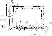
Fig. 1 is the cross-sectional view that is locked in each element together of snap tooth lock device of the present invention.
Fig. 2 is the decomposition diagram of the amplification of snap tooth lock device;
Fig. 3 is the cross-sectional view that each element of expression is locked in a time-out;
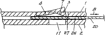
Fig. 4 is the local amplification sectional view that expression is locked in element under the state together; With
Fig. 5 is a local amplification sectional view of representing element under the released state each other.
Fig. 1 shows by a locking device according to the present invention, but is locked in together two elements 1,2 with the release form.In general, element 1 is the box of a hollow form, and another element 2 then forms a partly container of receiving element 1.
As depicted in figs. 1 and 2, element 1 has a tooth engaged 3 at elastic cantilever 4 ends, and this tooth is positioned at the rectangular channel 5 of the elongation that the sidewall 6 of element 1 limited.Tooth engaged 3 has a triangular cross section, and has an inclined-plane 7, and its surface is outwards facing to element 1.One section on the inclined-plane 7 stretches out outside the outer surface 8 of sidewall 6.Sidewall 6 also has a pair of parallel each other long and narrow seam 9,10, is set at the both sides of groove 5.
As shown in Figure 2, a release mechanism 20 is arranged between element 1 and 2 movably.On rectangular slab 25 opposed side edges 23,24, release mechanism 20 has two pairs of stay hooks that separate 21,22. Paired stay hook 21,22 is inserted in the corresponding seam 9,10 so that release mechanism 20 is remained under element 1 sidewall 6, insert in the seam 9,10 stay hook 21,22 can and move along seam 9,10.Like this, release mechanism 20 can slide to and fro along seam 9,10.The plate 25 of release mechanism 20 has a rectangular enclosure 26, and this chamber is the central authorities between each relative side roughly.Rectangular enclosure 26 has an inclined-plane 27 in the one side, and the inclined-plane 7 of this inclined-plane and tooth engaged 3 slidably mates, and this also will refer to afterwards.Release mechanism 20 has the extended joint 28 of pulling out on one side of slave plate 25, and the bearing of trend of this joint is parallel to the opposed side edges 23,24 of plate 25.
When element 1,2 is locked in a time-out, tooth engaged 3 is passed cavity 26 and is extended and engagement in hole 11.
Element 1 on element 2 locking and element 1 from element 2 process of unblanking, will be described with reference to accompanying drawing 3 to 5 below.
The element 1 that release mechanism 20 is housed is installed on the sidewall 12 of element 2.Simultaneously, tooth engaged 3 is loaded in the cavity 26 of release mechanism 20.When element 1 beginning contacted with the flange 16 of element 2, because the afterbody of tooth engaged 3 is held on the surface that is resisted against this sidewall 12, tooth engaged 3 flexiblely moved in the element 1, as shown in Figure 3.
As the indicated direction of arrow A among Fig. 3, element 1 is moved to the left, and enters hole 14 up to protuberance 15.Like this, tooth engaged 3 is thrown off from the surface of sidewall 12, under himself flexible effect, enters hole 11 rapidly, and with side surface 29 engagements in hole 11, as shown in Figure 4.Like this, element 1 has just been realized closely locking with corresponding element 2.
Element 1 unblanking from the element 2 as arrow B indicated direction among Fig. 5, extracted the joint 28 of pulling out of release mechanism 20 by the user, and release mechanism 20 is moved along seam 9,10.When release mechanism 20 quilts were mobile like this, the inclined-plane 27 on the release mechanism 20 slided with respect to the inclined-plane 7 of tooth engaged 3, forces tooth engaged 3 to be thrown off from hole 11.Continue to pull out joint 28, make tooth engaged 3 leave hole 11 fully, also leave cavity 26, and make cantilever 4 overcome the elasticity of himself and bend towards element 1, as shown in Figure 5.Further pulled out when pulling out joint 28,, from hole 26,11, deviate from the tooth engaged 3 of plate 25 engagements up to the end limit 30 that finally runs into seam 9,10 to stay hook in front.So far, element 1 is untied fully with the locking of element 2, and can separate from element 2.
When element 1 was locked with respect to element 2, because the elasticity of cantilever 4, inclined-plane 7 was pressed on the inclined-plane 27, and retaining mechanism 20 is remained on as shown in Figure 4 the position.In case correspondingly tooth engaged 3 is passed sky dirty 26 and engagement in hole 11, release mechanism 20 can stop moving to the chance of Fig. 4 dextrad.As a result, after element 1 was with respect to element 2 lockings, element 1 kept closely locking and is not unlocked, and pulls out joint 28 unless the user deliberately extracts artificially.
When the user pushes away element 1, enters rapidly in the hole 11 up to tooth engaged 3, element 1 can easily be locked with respect to element 2.The joint 28 of pulling out that drops on the release mechanism 20 as the user leaves hole 11 fully up to tooth engaged 3, and element 1 also can easily be unblanked from element 2.The user need not to use otherwise needs and puts in hole 11 by the outside, so that tooth engaged 3 is shifted out any special tool(s) in hole 11, and for easy unlock operation, does not need locked element 1,2 to shift one's position or change direction.
Although most preferred embodiment of the present invention described in detail in front,, be appreciated that various possible changes and improvements all do not break away from the scope of claims.
Claims (9)
1. snap tooth lock device that has quick unlock mechanism is characterized in that it includes:
Make foraminate first element on it for one;
Second element with resilient snap tooth, this tooth engaged and above-mentioned aperture can mesh by elastic type, and described first element and second element are locked toward each other;
One is arranged between described first and second elements, and the release mechanism that can move therein, and this mechanism is used for described tooth engaged is shifted out from aperture, so that described first and second elements latch-release to each other;
Described tooth engaged has one first inclined-plane, and described release mechanism has one second inclined-plane, and this second inclined-plane engages with described first inclined-plane slidably, when moving with the described release mechanism of box lunch described tooth engaged is shifted out from described aperture.
2. a kind of snap tooth lock device that has quick unlock mechanism as claimed in claim 1 is characterized in that described release mechanism is installed on described second element movably.
3. a kind of snap tooth lock device that has quick unlock mechanism as claimed in claim 2, it is characterized in that, described second element, at least make to have a seam on it, and described release mechanism has a stay hook that connects movably at least in above-mentioned seam, so that described release mechanism can move along described seam.
4. a kind of snap tooth lock device that has quick unlock mechanism as claimed in claim 3 is characterized in that, described release mechanism has a joint of pulling out along described seam extension.
5. a kind of snap tooth lock device that has quick unlock mechanism as claimed in claim 1, it is characterized in that, described release mechanism has work cavity thereon, described tooth engaged is passed cavity and is meshed with described hole, and described second inclined-plane is positioned at an end limit of described cavity.
6. a kind of snap tooth lock device that has quick unlock mechanism as claimed in claim 1 is characterized in that it also includes:
A release mechanism that is placed in movably on described first element makes to have a cavity on it;
The tooth engaged of described second element is passed described cavity and is engaged with elastic type in above-mentioned aperture, and described first element and second element are locked each other, and described release mechanism is installed on described second element movably; With
Described tooth engaged has one first inclined-plane, described release mechanism has one second inclined-plane on a limit of described cavity, it and the described first inclined-plane slip joint, therefore, motion corresponding to the described release mechanism of relevant described first and second element, by the slip joint between described first and second inclined-planes, described tooth engaged can be moved out of described aperture.
7. a kind of snap tooth lock device that has quick unlock mechanism as claimed in claim 6, it is characterized in that, described second element has a pair of separating, but parallel each other long and narrow seam, this seam is positioned at the both sides of described tooth engaged, and described release mechanism has the stay hook of the removable engagement of a pair of and above-mentioned seam at least, and therefore, described release mechanism can move along described seam.
8. a kind of snap tooth lock device that has quick unlock mechanism as claimed in claim 7, it is characterized in that, described release mechanism has comprised a rectangular slab with relative side, described stay hook correspondingly is placed in the opposed side edges of described plate, and one pulled out joint and protrude from described plate, and be parallel to described relative side.
9. a kind of snap tooth lock device that has quick unlock mechanism as claimed in claim 6, it is characterized in that, described first element has a flange, when described tooth engaged is passed described cavity and entered described aperture, is used for described second element of clamping to it.
Applications Claiming Priority (2)
| Application Number | Priority Date | Filing Date | Title |
|---|---|---|---|
| JP305120/90 | 1990-11-09 | ||
| JP2305120A JPH0793505B2 (en) | 1990-11-09 | 1990-11-09 | Claw lock device with lock release mechanism |
Publications (2)
| Publication Number | Publication Date |
|---|---|
| CN1062629A CN1062629A (en) | 1992-07-08 |
| CN1041887C true CN1041887C (en) | 1999-01-27 |
Family
ID=17941345
Family Applications (1)
| Application Number | Title | Priority Date | Filing Date |
|---|---|---|---|
| CN91111438A Expired - Fee Related CN1041887C (en) | 1990-11-09 | 1991-11-09 | Snap tooth lock device with quick unlock mechanism |
Country Status (8)
| Country | Link |
|---|---|
| US (1) | US5220712A (en) |
| JP (1) | JPH0793505B2 (en) |
| KR (1) | KR940006226B1 (en) |
| CN (1) | CN1041887C (en) |
| CA (1) | CA2055222C (en) |
| GB (1) | GB2250054B (en) |
| MY (1) | MY107919A (en) |
| TW (1) | TW278116B (en) |
Families Citing this family (33)
| Publication number | Priority date | Publication date | Assignee | Title |
|---|---|---|---|---|
| JPH06215530A (en) * | 1992-09-28 | 1994-08-05 | Fujitsu Ltd | Disk storage system |
| US5339501A (en) * | 1993-02-24 | 1994-08-23 | Illinois Tool Works Inc. | Snap and ratchet panel fastener and support assembly |
| US5488537A (en) * | 1994-03-28 | 1996-01-30 | Siemens Medical Systems, Inc. | Safety interconnect latch for portable medical electronic patient monitoring product |
| CA2148974A1 (en) * | 1994-05-13 | 1995-11-14 | Richard P. Brault | Turntable mechanism for a cutting tool |
| GB2290104B (en) * | 1994-06-09 | 1997-09-17 | Michael Sacks | A connector |
| DE19612843A1 (en) * | 1996-03-30 | 1997-10-02 | Telefunken Microelectron | Housing with means for attachment to a mounting plate |
| US5988583A (en) * | 1996-10-31 | 1999-11-23 | Qualcomm Incorporated | Antenna mounting assembly |
| JP3249936B2 (en) * | 1997-06-20 | 2002-01-28 | 住友金属工業株式会社 | Simple removable container with lid |
| DE19743949C1 (en) * | 1997-10-04 | 1998-11-26 | Telefunken Microelectron | Housing with latching mechanism on installation base surface |
| DE20203847U1 (en) * | 2002-03-09 | 2002-06-13 | GIRA Giersiepen GmbH & Co. KG, 42477 Radevormwald | Electric device |
| US6814377B2 (en) * | 2002-10-19 | 2004-11-09 | Fujitsu Limited | Computer quick release latch |
| TW200929680A (en) * | 2007-12-19 | 2009-07-01 | Wistron Neweb Corp | An antenna module and a positioning device thereof |
| TWI366432B (en) * | 2008-10-23 | 2012-06-11 | Inventec Corp | Unlocking structure and connector holding structure |
| CN101739094B (en) * | 2008-11-27 | 2012-06-13 | 英业达股份有限公司 | Buckling structure |
| WO2010106606A1 (en) * | 2009-03-18 | 2010-09-23 | 三菱電機株式会社 | Structure for fastening resin part |
| DE102009037350B3 (en) * | 2009-08-14 | 2011-07-21 | K.A. Schmersal Holding GmbH & Co. KG, 42279 | Tumbler for e.g. door and lid, for closing aperture, has recess formed as inner-extensive groove in insertion channel, and nose protruding from window of collet that is slidingly pre-tensioned opposite to nose under spring force |
| US9812684B2 (en) | 2010-11-09 | 2017-11-07 | GM Global Technology Operations LLC | Using elastic averaging for alignment of battery stack, fuel cell stack, or other vehicle assembly |
| TW201302004A (en) * | 2011-06-24 | 2013-01-01 | Hon Hai Prec Ind Co Ltd | Panel assembly |
| US9457845B2 (en) | 2013-10-02 | 2016-10-04 | GM Global Technology Operations LLC | Lobular elastic tube alignment and retention system for providing precise alignment of components |
| US9511802B2 (en) | 2013-10-03 | 2016-12-06 | GM Global Technology Operations LLC | Elastically averaged alignment systems and methods |
| US9669774B2 (en) | 2013-10-11 | 2017-06-06 | GM Global Technology Operations LLC | Reconfigurable vehicle interior assembly |
| US9541113B2 (en) | 2014-01-09 | 2017-01-10 | GM Global Technology Operations LLC | Elastically averaged alignment systems and methods |
| US9657807B2 (en) | 2014-04-23 | 2017-05-23 | GM Global Technology Operations LLC | System for elastically averaging assembly of components |
| US9452715B2 (en) * | 2014-11-03 | 2016-09-27 | GM Global Technology Operations LLC | Vehicle component coupling systems and methods |
| US9758110B2 (en) | 2015-01-12 | 2017-09-12 | GM Global Technology Operations LLC | Coupling system |
| US20160223004A1 (en) * | 2015-01-30 | 2016-08-04 | Alcatel - Lucent Canada, Inc. | Unit locking system and method |
| CN106354218A (en) * | 2015-07-15 | 2017-01-25 | 纬创资通(中山)有限公司 | Server case |
| CN106423335B (en) * | 2015-08-04 | 2018-12-25 | 中国科学院物理研究所 | It is a kind of for specimen holder to be locked to the locking device of sample stage |
| CN111374478B (en) * | 2015-11-17 | 2023-09-29 | 明门香港股份有限公司 | Folding structure of chair |
| JP7064993B2 (en) * | 2018-08-08 | 2022-05-11 | 株式会社アルファ | Vehicle door handle |
| CN110007089A (en) * | 2019-04-30 | 2019-07-12 | 深圳恩多克医疗有限公司 | It is a kind of to continue blood sugar monitoring transmitter and sensor unlocking mechanism |
| DE202020104684U1 (en) * | 2020-08-12 | 2020-08-19 | Georg Schlegel Gmbh & Co. Kg | Device for assembling a housing |
| CN112628263B (en) * | 2020-12-11 | 2022-07-12 | 江西影创信息产业有限公司 | Gear transmission is to inserting fixed knot and is constructed |
Citations (3)
| Publication number | Priority date | Publication date | Assignee | Title |
|---|---|---|---|---|
| US3836703A (en) * | 1973-10-19 | 1974-09-17 | Richco Plastic Co | Circuit board spacer-support |
| US4527312A (en) * | 1983-08-19 | 1985-07-09 | Illinois Tool Works Inc. | Stackable hinging printed circuit board support |
| US4613925A (en) * | 1983-07-05 | 1986-09-23 | Murata Manufacturing Co., Ltd. | Sensor attachment assembly |
Family Cites Families (9)
| Publication number | Priority date | Publication date | Assignee | Title |
|---|---|---|---|---|
| US2610875A (en) * | 1948-03-26 | 1952-09-16 | Harry L Wheelden | Extension ladder |
| US2896277A (en) * | 1956-07-30 | 1959-07-28 | Joseph C Halligan | Gate structure |
| US3522963A (en) * | 1967-10-13 | 1970-08-04 | Ind Electronic Eng Inc | Latching mechanism |
| DE3246042C2 (en) * | 1982-03-13 | 1985-01-17 | Festo-Maschinenfabrik Gottlieb Stoll, 7300 Esslingen | Connection device for producing a detachable plug connection |
| GB2121094B (en) * | 1982-05-27 | 1986-01-15 | Powell And Partners Limited Ri | Improvements relating to safety catches |
| DE3346243C2 (en) * | 1983-12-21 | 1986-09-18 | Siemens AG, 1000 Berlin und 8000 München | Snap connection between two elements |
| FR2566163B1 (en) * | 1984-06-13 | 1990-05-25 | Clarion Co Ltd | STRUCTURE FOR MOUNTING AND REMOVING AN APPARATUS IN A CAR |
| JPH06274Y2 (en) * | 1986-06-17 | 1994-01-05 | クラリオン株式会社 | Mounting device for in-vehicle electronic devices |
| JPS6377383U (en) * | 1986-11-07 | 1988-05-23 |
-
1990
- 1990-11-09 JP JP2305120A patent/JPH0793505B2/en not_active Expired - Lifetime
-
1991
- 1991-11-08 CA CA002055222A patent/CA2055222C/en not_active Expired - Fee Related
- 1991-11-08 GB GB9123761A patent/GB2250054B/en not_active Expired - Fee Related
- 1991-11-08 US US07/789,824 patent/US5220712A/en not_active Expired - Lifetime
- 1991-11-09 KR KR1019910019894A patent/KR940006226B1/en not_active IP Right Cessation
- 1991-11-09 CN CN91111438A patent/CN1041887C/en not_active Expired - Fee Related
- 1991-11-09 MY MYPI91002074A patent/MY107919A/en unknown
- 1991-11-11 TW TW080108922A patent/TW278116B/zh active
Patent Citations (3)
| Publication number | Priority date | Publication date | Assignee | Title |
|---|---|---|---|---|
| US3836703A (en) * | 1973-10-19 | 1974-09-17 | Richco Plastic Co | Circuit board spacer-support |
| US4613925A (en) * | 1983-07-05 | 1986-09-23 | Murata Manufacturing Co., Ltd. | Sensor attachment assembly |
| US4527312A (en) * | 1983-08-19 | 1985-07-09 | Illinois Tool Works Inc. | Stackable hinging printed circuit board support |
Also Published As
| Publication number | Publication date |
|---|---|
| GB9123761D0 (en) | 1992-01-02 |
| GB2250054B (en) | 1994-06-01 |
| MY107919A (en) | 1996-06-29 |
| CA2055222C (en) | 1995-08-01 |
| KR940006226B1 (en) | 1994-07-13 |
| CA2055222A1 (en) | 1992-05-10 |
| GB2250054A (en) | 1992-05-27 |
| CN1062629A (en) | 1992-07-08 |
| US5220712A (en) | 1993-06-22 |
| JPH0793505B2 (en) | 1995-10-09 |
| JPH04177797A (en) | 1992-06-24 |
| TW278116B (en) | 1996-06-11 |
| KR920011309A (en) | 1992-06-27 |
Similar Documents
| Publication | Publication Date | Title |
|---|---|---|
| CN1041887C (en) | Snap tooth lock device with quick unlock mechanism | |
| SU730317A3 (en) | Photograph viewing device | |
| US4256356A (en) | Apparatus for inserting and withdrawing subassemblies | |
| DE19525413A1 (en) | Plug connection recognition apparatus | |
| US6058579A (en) | Snap latch insertion/removal lever | |
| DE10124537A1 (en) | Cordless power tool employs rechargeable battery container section forming unit with handle and push button release for facilitating battery extraction | |
| DE3818092C2 (en) | ||
| EP3700390A1 (en) | Storage device | |
| CN208190786U (en) | A kind of video camera | |
| EP1169840A1 (en) | Casing | |
| EP0202307A1 (en) | Container for piles of pictures. | |
| DE4011722A1 (en) | Catch for lid of box - has magnet to hold lid closed and is released by pressing slider into catch housing | |
| DE60320438T2 (en) | DEVICE FOR THE LOCKED INSTALLATION OF A DEVICE DESIGNED FOR RACK MOUNTING | |
| DE69511270T2 (en) | INTERCONNECTS | |
| CN2613974Y (en) | Mistake-proofing device for hard disk drawing | |
| US3239904A (en) | Flexible fastener and slider | |
| DE202004000980U1 (en) | Elastic buckle | |
| EP1177740A1 (en) | Fastening device for the shoulder-strap of a handbag | |
| DE7727582U1 (en) | MICROFICH READER | |
| DE3702628A1 (en) | STACKABLE CONTAINER FOR TAPE TAPES | |
| WO2023129080A1 (en) | Cable retaining configuration | |
| EP3689210B1 (en) | Vacuum cleaner with drawer | |
| CN214904399U (en) | Pull rod and draw-bar box | |
| EP1397032B1 (en) | Assisting device | |
| DE287128C (en) |
Legal Events
| Date | Code | Title | Description |
|---|---|---|---|
| C10 | Entry into substantive examination | ||
| SE01 | Entry into force of request for substantive examination | ||
| C06 | Publication | ||
| PB01 | Publication | ||
| C14 | Grant of patent or utility model | ||
| GR01 | Patent grant | ||
| C15 | Extension of patent right duration from 15 to 20 years for appl. with date before 31.12.1992 and still valid on 11.12.2001 (patent law change 1993) | ||
| OR01 | Other related matters | ||
| C19 | Lapse of patent right due to non-payment of the annual fee | ||
| CF01 | Termination of patent right due to non-payment of annual fee |