CN1040090C - Rewinder for producing logs of web material, selectively with or without a winding core - Google Patents
Rewinder for producing logs of web material, selectively with or without a winding core Download PDFInfo
- Publication number
- CN1040090C CN1040090C CN94192394A CN94192394A CN1040090C CN 1040090 C CN1040090 C CN 1040090C CN 94192394 A CN94192394 A CN 94192394A CN 94192394 A CN94192394 A CN 94192394A CN 1040090 C CN1040090 C CN 1040090C
- Authority
- CN
- China
- Prior art keywords
- fuse
- roller bearing
- rewinder
- coiled strip
- volume
- Prior art date
- Legal status (The legal status is an assumption and is not a legal conclusion. Google has not performed a legal analysis and makes no representation as to the accuracy of the status listed.)
- Expired - Fee Related
Links
Images


Classifications
-
- B—PERFORMING OPERATIONS; TRANSPORTING
- B65—CONVEYING; PACKING; STORING; HANDLING THIN OR FILAMENTARY MATERIAL
- B65H—HANDLING THIN OR FILAMENTARY MATERIAL, e.g. SHEETS, WEBS, CABLES
- B65H19/00—Changing the web roll
- B65H19/22—Changing the web roll in winding mechanisms or in connection with winding operations
- B65H19/2238—The web roll being driven by a winding mechanism of the nip or tangential drive type
- B65H19/2269—Cradle
-
- B—PERFORMING OPERATIONS; TRANSPORTING
- B65—CONVEYING; PACKING; STORING; HANDLING THIN OR FILAMENTARY MATERIAL
- B65H—HANDLING THIN OR FILAMENTARY MATERIAL, e.g. SHEETS, WEBS, CABLES
- B65H19/00—Changing the web roll
- B65H19/22—Changing the web roll in winding mechanisms or in connection with winding operations
- B65H19/2276—The web roll being driven by a winding mechanism of the coreless type
-
- B—PERFORMING OPERATIONS; TRANSPORTING
- B65—CONVEYING; PACKING; STORING; HANDLING THIN OR FILAMENTARY MATERIAL
- B65H—HANDLING THIN OR FILAMENTARY MATERIAL, e.g. SHEETS, WEBS, CABLES
- B65H19/00—Changing the web roll
- B65H19/22—Changing the web roll in winding mechanisms or in connection with winding operations
- B65H19/26—Cutting-off the web running to the wound web roll
- B65H19/267—Cutting-off the web running to the wound web roll by tearing or bursting
-
- B—PERFORMING OPERATIONS; TRANSPORTING
- B65—CONVEYING; PACKING; STORING; HANDLING THIN OR FILAMENTARY MATERIAL
- B65H—HANDLING THIN OR FILAMENTARY MATERIAL, e.g. SHEETS, WEBS, CABLES
- B65H2301/00—Handling processes for sheets or webs
- B65H2301/40—Type of handling process
- B65H2301/41—Winding, unwinding
- B65H2301/417—Handling or changing web rolls
- B65H2301/418—Changing web roll
- B65H2301/4181—Core or mandrel supply
- B65H2301/41812—Core or mandrel supply by conveyor belt or chain running in closed loop
-
- B—PERFORMING OPERATIONS; TRANSPORTING
- B65—CONVEYING; PACKING; STORING; HANDLING THIN OR FILAMENTARY MATERIAL
- B65H—HANDLING THIN OR FILAMENTARY MATERIAL, e.g. SHEETS, WEBS, CABLES
- B65H2301/00—Handling processes for sheets or webs
- B65H2301/40—Type of handling process
- B65H2301/41—Winding, unwinding
- B65H2301/417—Handling or changing web rolls
- B65H2301/418—Changing web roll
- B65H2301/4182—Core or mandrel insertion, e.g. means for loading core or mandrel in winding position
- B65H2301/41824—Core or mandrel insertion, e.g. means for loading core or mandrel in winding position from below, e.g. between rollers of winding bed
-
- B—PERFORMING OPERATIONS; TRANSPORTING
- B65—CONVEYING; PACKING; STORING; HANDLING THIN OR FILAMENTARY MATERIAL
- B65H—HANDLING THIN OR FILAMENTARY MATERIAL, e.g. SHEETS, WEBS, CABLES
- B65H2301/00—Handling processes for sheets or webs
- B65H2301/40—Type of handling process
- B65H2301/41—Winding, unwinding
- B65H2301/417—Handling or changing web rolls
- B65H2301/418—Changing web roll
- B65H2301/4182—Core or mandrel insertion, e.g. means for loading core or mandrel in winding position
- B65H2301/41826—Core or mandrel insertion, e.g. means for loading core or mandrel in winding position by gripping or pushing means, mechanical or suction gripper
-
- B—PERFORMING OPERATIONS; TRANSPORTING
- B65—CONVEYING; PACKING; STORING; HANDLING THIN OR FILAMENTARY MATERIAL
- B65H—HANDLING THIN OR FILAMENTARY MATERIAL, e.g. SHEETS, WEBS, CABLES
- B65H2301/00—Handling processes for sheets or webs
- B65H2301/40—Type of handling process
- B65H2301/41—Winding, unwinding
- B65H2301/417—Handling or changing web rolls
- B65H2301/4187—Relative movement of core or web roll in respect of mandrel
- B65H2301/4189—Cutting
- B65H2301/41894—Cutting knife moving on circular or acuate path, e.g. pivoting around winding roller
-
- B—PERFORMING OPERATIONS; TRANSPORTING
- B65—CONVEYING; PACKING; STORING; HANDLING THIN OR FILAMENTARY MATERIAL
- B65H—HANDLING THIN OR FILAMENTARY MATERIAL, e.g. SHEETS, WEBS, CABLES
- B65H2406/00—Means using fluid
- B65H2406/10—Means using fluid made only for exhausting gaseous medium
- B65H2406/11—Means using fluid made only for exhausting gaseous medium producing fluidised bed
- B65H2406/112—Means using fluid made only for exhausting gaseous medium producing fluidised bed for handling material along preferably rectilinear path, e.g. nozzle bed for web
-
- B—PERFORMING OPERATIONS; TRANSPORTING
- B65—CONVEYING; PACKING; STORING; HANDLING THIN OR FILAMENTARY MATERIAL
- B65H—HANDLING THIN OR FILAMENTARY MATERIAL, e.g. SHEETS, WEBS, CABLES
- B65H2408/00—Specific machines
- B65H2408/20—Specific machines for handling web(s)
- B65H2408/23—Winding machines
- B65H2408/235—Cradles
-
- B—PERFORMING OPERATIONS; TRANSPORTING
- B65—CONVEYING; PACKING; STORING; HANDLING THIN OR FILAMENTARY MATERIAL
- B65H—HANDLING THIN OR FILAMENTARY MATERIAL, e.g. SHEETS, WEBS, CABLES
- B65H2511/00—Dimensions; Position; Numbers; Identification; Occurrences
- B65H2511/20—Location in space
- B65H2511/22—Distance
- B65H2511/224—Nip between rollers, between belts or between rollers and belts
-
- B—PERFORMING OPERATIONS; TRANSPORTING
- B65—CONVEYING; PACKING; STORING; HANDLING THIN OR FILAMENTARY MATERIAL
- B65H—HANDLING THIN OR FILAMENTARY MATERIAL, e.g. SHEETS, WEBS, CABLES
- B65H2513/00—Dynamic entities; Timing aspects
- B65H2513/10—Speed
Landscapes
- Replacement Of Web Rolls (AREA)
- Rolls And Other Rotary Bodies (AREA)
- Winding Of Webs (AREA)
- Nonwoven Fabrics (AREA)
- Basic Packing Technique (AREA)
- Paper (AREA)
Abstract
A surface automatic rewinder for winding web material (N) in logs or rolls (R) is described, including a first winder roller (1), a second winder roller (3) which defines, with the first winder roller, a nip (5) through which the web material is fed, core feeder (19, 21) to feed the cores (A) on which the web material is wound for the formation of rolls or logs, and an inserter (27) for inserting the cores into the nip (5). The rewinder is characterized in that the inserter (27) may be moved to an inoperative position whereupon the winding of the web material can be accomplished without a winding core.
Description
The present invention relates to a kind of automatic surface rewinder, in order to a kind of coiled strip is wound up on the fuse to make the material volume.These facility have: a first volume is around roller bearing; One the 2nd coiling roller bearing, this roller bearing and the first volume constitute a gap around roller bearing, by this gap feed coiled strip; Feeder, in order to the feed fuse, the coiling coiled strip is to make the material volume on this fuse; One Quick Pulse System is in order to import fuse in described gap.
This rewinder is known, for example, can be from US Patent 4,487, learn in 377 and 5,137,225 or from the GB2 of British patent, 105,688.This rewinder generally is used for paper transformation of the way industry, in order to wind off the beginning from original major diameter material, produces the less material volume of some diameters, then it is cut into the toilet paper of rouleau, how with wiping away paper, industry material volume or similar articles for use.
Also once attempted to provide in order to produce the rewinder of no core material volume.For example, US Patent 4,487,378 illustrate and a kind ofly here, reel on a plug earlier in order to produce the device of material volume, again from the finish mix volume with its extraction.This class wind2 can not adapt to quantity-produced requirement in current this field.
An object of the present invention is to provide the automatic rewinder in a kind of surface, can winding core be arranged or do not have the material volume of winding core in order to High-efficient Production.Another object of the present invention provides a kind of rewinder, can extremely rapidly, simply, not need the special ground of regulating to have the core material volume switching to roll up to producing no core material from production, and can do oppositely directed conversion.
These purposes and to being skillful in these professional personnel having read other purposes and the advantage that following explanation can be understood just can be finished with the rewinder of a above-mentioned type, and it is characterized in that: the fuse Quick Pulse System can move on on the off-position; Adopted some devices, made without winding core just to begin to expect the coiling rolled up, described wind2 can be relatively having or is not having under the situation of fuse feed and Quick Pulse System and work.
Notice above-mentioned and other purposes, just can obtain further understanding the present invention referring to following detailed explanation.
Be explanation the present invention, wherein a kind of pattern shown in the drawings, just at present, this is a kind of preferred pattern, but be understood that and make various layout and combination, the restriction that these device institutes are prepared and arrange and make up that the present invention is not subjected to illustrate here and illustrate constituting the various device of the present invention.
In following each figure, identical reference number is represented identical member:
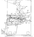
Fig. 1 illustrates first embodiment of rewinder of the present invention briefly, and this machine is in the serviceability of producing tape wrapping fuse material volume.
Fig. 2 illustrates rewinder shown in Figure 1, and this machine is through prearranging the state of producing no winding core material volume that is in.
Fig. 3 illustrates the 2nd embodiment of rewinder of the present invention briefly, and this machine is in the serviceability of producing tape wrapping fuse material volume.
Fig. 4 illustrates rewinder shown in Figure 3, and this machine is in the state of producing no winding core material volume.
Fig. 5 illustrates the 3rd embodiment of rewinder.
Production with regard to belt carcass material volume, the structure of rewinder shown in Figure 1 is disclosed similar to the US Patent that is in simultaneously in the trial, and this patent proposed on July 9th, 1992, its application number 07/911,055 and EP-A-0524158, it is for reference that its content is listed the present invention in.
Earlier with regard to produce tape wrapping fuse material volume the member that should possess, rewinder shown in Figure 1 has a first volume around the roller bearing 1 and the second coiling roller bearing 3, this two roller bearing constitutes a gap 5, the coiled strip N that need reel by this gap feed.1A is depicted as the cylindrical surface of roller bearing 1.Gap 5 has one across size under this state, this size is equal to or slightly less than the diameter of the fuse A of the coiled strip of reeling in the above.The 3rd coiling roller bearing 7 constitutes one in order to form the coiling space of material volume, is supported on the connecting lever 9, and this connecting lever rotates with frame at 11 places and is connected.Roller bearing 7 moves up gradually around axis 11, and the diameter that material is rolled up is increased in forming process and controls.Coiled strip N unwinding from the feed roller bearing (not shown) is got off, and with one group of transmission and guiding roller bearing 13,15 with its guiding winding area.Before arriving the winding area that is made of roller bearing 1,3 and 7, coiled strip N bores a hole along horizontal line to coiled strip in this device by a driling unit 17.
Numeral 19 total expressions are reeled coiled strip thereon to produce the device of the fuse A that expects volume in order to feed.This device 19 has an endless belt conveyer 21, and this belt conveyor is equipped with a pack support 23, places fuse A thereon, fuse one by one from a hopper container or allied equipment (not shown) sort out.Each fuse A through a glue spreading apparatus 25, coats skim glue thereon, makes the forward position of coiled strip sticking thereon.Each fuse by belt conveyor 21 feeds is picked up by a Quick Pulse System 27, and this device rotates with frame at 29 places and is connected, and has an intermittence swing synchronous with machine speed.After finishing material volume, Quick Pulse System 27 is with in the gap 5 between the another fuse A importing roller bearing 1 and 3.The material volume that coiled strip is pulled apart, will be finished is discharged on the surface 31 and makes another material wind off the beginning and reels, and this is all undertaken by known method.
Described member so far can be rolled up in order to the material of producing the tape wrapping fuse, but this machine also can be in order to produce the material volume of no winding core through arrangement.For this reason, be provided with in the present embodiment and be contained on the connecting lever 35 and at 37 places and frame bonded assembly one device 33 that rotates.In Fig. 1, present position when this device 33 is shown in broken lines its inoperative.There is not material when volume of fuse A in need production, the state of the state-transition of each member of machine from Fig. 1 in Fig. 2.
As shown in Figure 2, transferred to the left side and left the winding area for core apparatus 19.This is to finish by described confession core apparatus being contained on the vehicle frame 20 by a motor driven.
From the shown in Figure 1 state that withdraw from a clockwise direction turn to and the reel state of roller bearing 1 and 3 collaborative works, each other draw close by this two roller bearing for device 33.Meanwhile, Quick Pulse System 27 is converted to lower exit status (being shown in broken lines) around axis 29 with the mode of operation of anticlockwise direction from Fig. 1 in Fig. 2.
In fact, under state shown in Figure 2, motor 43 is to drive in the previous short time of material volume coiling end.This just make device 33 (thereby surface 41) be loaded on the arm 51 and collaborative work with the cam 46 of follower 49 under move to roller bearing 1.The This move of motor 43 also makes surface 41 because the effect of eccentric stiffener 48 is moved to roller bearing 1.These two kinds of wobbling actions add just makes surface 41 only contact once with the surface of roller bearing 1 when cam 46 rotates a circle together.This just pulls apart coiled strip N, and makes thereby the free forward position self that forms is rolled to produce another material volume.Very fast its diameter of increase of initial several circles of Xing Chenging and surface, edge 41 are rolled in the gap 5 like this, again through entering here by in this 1.3 and 7 coiling space that constitutes.It is could pass through gap 5 owing to exist difference on the speed (for the moment or for a long time) between roller bearing 1 and 3 that material twists in the forming process.Pull apart coiled strip N and make its free edge along the process self rolled of beginning aforementioned in 08/090, No. 519 application that proposed on July 3rd, 1993 (be equivalent to proposed on July 20th, 1993 EP93830312.0 number application) done very detailed explanation.Device 33 can be made by arbitrary embodiment described in the above-mentioned patent application.
For making the device 33 that is contained on the arm 35 be converted to the mode of operation of Fig. 2, be provided with a lift system, comprise a revolving actuator 53 and a flexure member 55, one end of this member is fixed on the actuator 53, and its other end is fixed on the attachment point 57 of machine by the elastic buffering mechanism 59 of middle plug-in mounting.But transmission flexure member 55 also makes it walk around a little roller bearing 61 that is contained on the arm 51.Because flexure member 55 is rolled onto on the actuator 53, this has just promoted arm 51, again because the collaborative work between cam 46 and the follower 49 has also just promoted arm 35, thereby has promoted device 33.Two arms 35 and two arms 51 and corresponding device 53,55 in order to bont 33 should be set in actual applications, respectively establish one in the both sides of machine.In working order down, arm 51 keeps abutting against on two adjustable seats (not shown)s by flexure member 55, and bearing is respectively established one in the both sides of machine, there is no contact to each other.
Because it is much smaller than winding core A that the material of the no winding core made twists in when entering gap 5 its diameter, so rewinder of the present invention has the mechanism that coiling roller bearing 1 and 3 is drawn close each other, so that press the width in the kind change gap 5 of products made thereby.
In the embodiment of Fig. 1 and 2, be provided with crankshaft- connecting rod mechanism 65,67 with axle 69 transmissions.This mechanism does not make roller bearing 1 draw close this axle 3 when rewinder production has the core material volume, thereby the axis of roller bearing 1 moves on to position X ' (Fig. 2) from position X.This displacement is by obtaining around the arm 70 of a pivot 72 rotating support roller bearings 1.Certainly, also can adopt the action that makes roller bearing 3 draw close roller bearing 1.In addition, as can be seen, having core material volume to change into to produce no core material from production when rolling up when comparison diagram 1 and Fig. 2, the route of coiled strip has also changed.This make roller bearing 1 from the mechanism 65,67,69 (as being controlled) that position X transfers to X ' with a suitable servomotor also can the machine works process, be used for the material that just begins to reel twist between roller bearing 1 and 3 by the time move roller bearing 1.This is for the suffered extruding of described material volume is remained on the minimum level.
Fig. 3 and 4 illustrates another embodiment of rewinder of the present invention.In the following description, earlier with regard to Fig. 3, this illustrates in order to produce the structure of tape wrapping fuse material volume.This device that is used for producing the core material volume is the italian patent of FI93A58 in this case corresponding to application number, and its content is a component part of this explanation.Numeral 101,103,107 expressions are corresponding to the coiling roller bearing of roller bearing among Fig. 11,3,7.Numeral 101A represents the cylindrical surface of roller bearing 101.The gap that 105 expressions are made of roller bearing 101 and 103.Roller bearing 107 is supported on one on 111 places and frame rotate bonded assembly connecting lever 109.Roller bearing 107 moves up gradually around axis 111, so that material coil diameter is increased and controls in manufacturing process.Coiled strip N expects that volume goes up that the (not shown) unwinding is got off and by one group of transmission and guiding roller bearing 113,115 guiding winding areas from a feed former.Before arriving the winding area that constitutes by roller bearing 101,103 and 107, bore a hole along horizontal line by 117 couples of coiled strip N of a perforation group.
Numeral 119 devices of generally speaking representing in order to feed fuse A, coiling coiled strip N is to produce the material volume on this fuse.Device 119 has an endless belt conveyer 121 that has a pack support 123, gets fuse in order to choose one at a time from the oblique end surface 120 of a kind of hopper container or allied equipment (not shown).Each fuse A in order to coat skim glue thereon, is fixed on the described fuse forward position of coiled strip through a glue spreading apparatus 125.Shed from belt conveyor by a Quick Pulse System 127 by each fuses of belt conveyor 121 feeds, this device is made of a flat board around axis 128 rotations, and the rotation axis of one of them power wheel of this axis and endless belt conveyer 121 coincides.
Coiled strip N pulls apart by one group of pressurizer 134, and pressurizer passes through 132 of thin plates around 136 rotations of himself axis, and clamps coiled strip between the surface of himself surface and roller bearing 101.Pressurizer 134 rotates off and on, and its circumferential velocity that is pressed in the surface on the roller bearing 101 is lower than the circumferential velocity of this roller bearing.Pulling apart coiled strip N as application number by means of difference between the speed is as described in the italian patent of FI93A58.
For there is core material volume with production of machinery shown in Fig. 3 and 4, should take measures to leave the winding area with the top of belt conveyor 121, gluing group 125, Quick Pulse System 127 and by axle that supports pressurizer 134 and device that thin plate 132 constitutes.This finishes by it is moved along roller bearing guide piece 140.Meanwhile, also drawn close coiling roller bearing 101 by the device 133 (substantially corresponding to device 33) that axle 137 supports, this is that rotation axis with roller bearing 103 coincides in this case.Numeral 141 expressions are corresponding to a surface on surface 41 among Fig. 1 and 2.143,145,146,147,148 and 149 expressions are corresponding to 43,45,46,47,48 and 49 member among Fig. 1 and 2.The arm 151 that follower 149 is housed is connected on the cylinder piston actuator 153, and this activates utensil the effect identical with mechanism 53,55 among Fig. 1 and 2.154 represent an adjustable support, and corresponding arm 151 is in working order down near in the above.
With so that the mechanism that roller bearing 101 and 103 is drawn close each other omits in Fig. 3 and 4, this mechanism is to similar shown in Fig. 1 and 2.
Be understood that, can be different from person shown in above two embodiment in order to the rewinder of producing tape wrapping fuse material volume, in fact can select for use at present can be in order to the structure that any machine adopted of special production tape wrapping fuse material volume.
Fig. 5 illustrates another embodiment, and wherein coreless winding draws by coiling roller bearing 101 and 103 direct collaborative works.Member corresponding to Fig. 3 and Fig. 4 adopts identical reference number.The support arm that numeral 201 expressions are supported roller bearing 101 and rotated around pivot at 203 places.Numeral 205 expressions and actuator 207 bonded assemblys form an elastic link of a cylinder piston mechanism.Mechanism 205,207 makes roller bearing 101 rotate around pivot 203.By one suitable for long travel, roller bearing 101 is drawn close roller bearing 103 to carry out coreless winding.Under this condition of drawing close, the fuse conveyer is removed, shown in Fig. 4 embodiment.Having produced in the case with application number is 090,519 the identical coreless winding of the described process of US Patent, and it is for reference that the content of this patent is listed this explanation in.Roller bearing 101 and 103 surface periodic ground are drawn close each other compressing coiled strip therebetween, thereby pull apart coiled strip, and it self is rolled pulling apart the back.
Be understood that accompanying drawing is just in order to exemplarily doing actual explanation to the present invention, in form and disposal, can change and do not break away from basic design scope of the present invention.The reference number that may occur in claims is just for the ease of understanding claim by explanation and accompanying drawing, do not limit claim the protection domain that is proposed.
Claims (6)
1. an automatic surface rewinder is rolled up (R) in order to coiled strip (N) is wound into material, and comprising: a first volume is around roller bearing (1; 101); One second coiling roller bearing (3; 103), constitute a gap (5 around roller bearing with the first volume; 105), by this gap feed coiled strip (N); Feeder (19,21; 119,121), in order to feed fuse (A), coiled strip can be reeled thereon to make the material volume; And Quick Pulse System (27; 127),, it is characterized in that in order to fuse is imported described gap:
Fuse feeder (19,21; 119; 121) and fuse Quick Pulse System (27; 127) be movable to an off-position;
Coreless winding device (33 is housed; 133), selectively cause the coiling of the no core material volume of coiled strip, when fuse feeder and fuse Quick Pulse System were in off-position, described wind2 alternately carried out work;
The described first and second coiling roller bearings (1,3; 101,103) distance between is adjustable; In fuse Quick Pulse System (27; When 127) being in off working state, the first and second coiling roller bearings are drawn close each other to dwindle described gap (5; 105) width;
Also comprise the device of pulling apart coiled strip.
2. by the described rewinder of claim 1, it is characterized in that: these facility have actuating device (207), this device periodically makes described two coiling roller bearings (101 in fuse Quick Pulse System (127) when being in off working state, 103) do respect to one another moving, one of them the time is pressed on above another to make another volume beginning coiling work at every turn, thereby pull apart coiled strip, its free edge is rolled along self.
3. by claim 1 or 2 described rewinders, it is characterized in that: these facility have: with a movable surfaces (1A; A 101A) rolling surface (41 of formation one passage; 141); Coiled strip moves on the movable surface, and the no core material volume that begins to reel in this passage; Device (43-49; 143-149), this device makes rolling surface (41; 141) and movable surfaces periodically each other collaborative work so that begin to reel no core material volume (R), described rolling surface (41; 141) can between a control position and an off-position, move.
4. by the described rewinder of claim 1, it is characterized in that: fuse Quick Pulse System (27) rotates with the rewinder frame and is connected so that around a pivot swinging, thereby moves on on the off-position.
5. by the described rewinder of claim 1, it is characterized in that: fuse feed and Quick Pulse System (19; 119) can be with respect to coiling roller bearing (1,3; 101,103) move.
6. by the described rewinder of claim 3, it is characterized in that: described rolling surface (41; 141) be contained in a device (33; 133) on, this device is parallel to the first volume around roller bearing (1 around one; 101) axis (37; 137) swing, described device can be got off working state around described axis swing.
Applications Claiming Priority (2)
| Application Number | Priority Date | Filing Date | Title |
|---|---|---|---|
| ITFI93A000109 | 1993-06-09 | ||
| IT93FI000109A IT1265867B1 (en) | 1993-06-09 | 1993-06-09 | REWINDING MACHINE FOR THE PRODUCTION OF ROLLS OF RAPE MATERIAL ALTERNATIVELY WITH OR WITHOUT WINDING CORE |
Publications (2)
| Publication Number | Publication Date |
|---|---|
| CN1124947A CN1124947A (en) | 1996-06-19 |
| CN1040090C true CN1040090C (en) | 1998-10-07 |
Family
ID=11350489
Family Applications (1)
| Application Number | Title | Priority Date | Filing Date |
|---|---|---|---|
| CN94192394A Expired - Fee Related CN1040090C (en) | 1993-06-09 | 1994-06-01 | Rewinder for producing logs of web material, selectively with or without a winding core |
Country Status (18)
| Country | Link |
|---|---|
| US (1) | US5603467A (en) |
| EP (1) | EP0738231B1 (en) |
| JP (1) | JP3428019B2 (en) |
| KR (1) | KR100202227B1 (en) |
| CN (1) | CN1040090C (en) |
| AT (1) | ATE161796T1 (en) |
| AU (1) | AU6981194A (en) |
| BR (1) | BR9406768A (en) |
| CA (1) | CA2164870C (en) |
| DE (1) | DE69407820T2 (en) |
| ES (1) | ES2111308T3 (en) |
| FI (1) | FI117169B (en) |
| GR (1) | GR3026093T3 (en) |
| IL (1) | IL109718A (en) |
| IT (1) | IT1265867B1 (en) |
| PL (1) | PL174862B1 (en) |
| RU (1) | RU2120399C1 (en) |
| WO (1) | WO1994029205A1 (en) |
Families Citing this family (55)
| Publication number | Priority date | Publication date | Assignee | Title |
|---|---|---|---|---|
| DE4401027C2 (en) * | 1994-01-15 | 1995-11-09 | Voith Gmbh J M | Carrier drum roller for a paper machine |
| US5620148A (en) | 1995-03-10 | 1997-04-15 | Kimberly-Clark Corporation | Methods of making indented coreless rolls |
| US6439502B1 (en) | 1995-02-28 | 2002-08-27 | Kimberly-Clark Worldwide, Inc. | Dispenser for coreless rolls of products |
| US5875985A (en) * | 1995-03-10 | 1999-03-02 | Kimberly-Clark Worldwide, Inc. | Indented coreless rolls and method of making the same |
| DE29515848U1 (en) * | 1995-10-06 | 1995-12-07 | Maschinenfabrik Goebel Gmbh, 64293 Darmstadt | Device for winding a web |
| US5725176A (en) | 1996-01-19 | 1998-03-10 | Paper Converting Machine Co. | Method and apparatus for convolute winding |
| US5772149A (en) * | 1996-09-18 | 1998-06-30 | C. G. Bretting Manufacturing Company, Inc. | Winding control finger surface rewinder |
| US5820064A (en) * | 1997-03-11 | 1998-10-13 | C.G. Bretting Manufacturing Company, Inc. | Winding control finger surface rewinder with core insert finger |
| US6000657A (en) * | 1996-09-18 | 1999-12-14 | C.G. Bretting Manufacturing Company, Inc. | Winding control finger surface rewinder with core insert finger |
| US6092759A (en) | 1997-09-08 | 2000-07-25 | Kimberly-Clark Worldwide, Inc. | System for dispensing coreless rolls of product |
| US6092758A (en) | 1997-09-08 | 2000-07-25 | Kimberly-Clark Worldwide, Inc. | Adapter and dispenser for coreless rolls of products |
| US6082664A (en) | 1997-11-20 | 2000-07-04 | Kimberly-Clark Worldwide, Inc. | Coreless roll product and adapter |
| US6360985B1 (en) | 1998-05-29 | 2002-03-26 | Kimberly-Clark Worldwide, Inc. | Dispenser adapter for coreless rolls of products |
| USD428286S (en) * | 1998-05-29 | 2000-07-18 | Kimberly-Clark Worldwide | Dispenser adapter for coreless rolls of products |
| US6138939A (en) | 1998-08-17 | 2000-10-31 | Kimberly Clark Worldwide, Inc. | Coreless adapter for dispensers of cored rolls of material |
| US6056229A (en) * | 1998-12-03 | 2000-05-02 | Paper Converting Machine Co. | Surface winder with pinch cutoff |
| IT249984Y1 (en) * | 2000-12-27 | 2003-07-07 | Gambini Giovanni | REWINDING DEVICE TO FORM A PAPER ROLL IN A REWINDER MACHINE |
| ITMI20010764A1 (en) * | 2001-04-10 | 2002-10-10 | Gambini Giovanna | APPARATUS TO APPLY GLUE TO A SOUL TO BE INSERTED IN A REWINDER TO WIND LOG |
| ITMI20010306U1 (en) * | 2001-06-01 | 2002-12-02 | Gambini Giovanni | DEVICE FOR REWINDING AND FORMING A CARTAIN ROLL A REWINDING MACHINE |
| US7101587B2 (en) * | 2001-07-06 | 2006-09-05 | Kimberly-Clark Worldwide, Inc. | Method for wetting and winding a substrate |
| US6649262B2 (en) * | 2001-07-06 | 2003-11-18 | Kimberly-Clark Worldwide, Inc. | Wet roll having uniform composition distribution |
| US20030113458A1 (en) * | 2001-12-18 | 2003-06-19 | Kimberly Clark Worldwide, Inc. | Method for increasing absorption rate of aqueous solution into a basesheet |
| US6866220B2 (en) | 2001-12-21 | 2005-03-15 | Kimberly-Clark Worldwide, Inc. | Continuous motion coreless roll winder |
| US7175127B2 (en) * | 2002-09-27 | 2007-02-13 | C.G. Bretting Manufacturing Company, Inc. | Rewinder apparatus and method |
| US7238236B2 (en) * | 2002-11-14 | 2007-07-03 | Kimberly-Clark Worldwide, Inc. | Apparatus for increasing tail adhesion of wet rolls |
| ITFI20020227A1 (en) * | 2002-11-20 | 2004-05-21 | Perini Fabio Spa | REWINDER MACHINE WITH A GLUING DEVICE FOR GLUING THE FINAL FLAP OF THE ROLL FORMED AND RELATED WINDING METHOD |
| ITFI20030118A1 (en) * | 2003-04-28 | 2004-10-29 | Fabio Perini | DEVICE AND METHOD TO CAUSE THE TAPPING OF PAPER TAPES IN REWINDING MACHINES |
| US7222813B2 (en) * | 2005-03-16 | 2007-05-29 | Chan Li Machinery Co., Ltd. | Multiprocessing apparatus for forming logs of web material and log manufacture process |
| ITFI20050086A1 (en) * | 2005-05-02 | 2006-11-03 | Perini Fabio Spa | ROLL OF MATTRIFIED MATERIALS WITHOUT CENTRAL WINDING SOUL, MACHINES AND METHOD FOR ITS PRODUCTION |
| ITFI20050087A1 (en) * | 2005-05-02 | 2006-11-03 | Perini Fabio Spa | METHOD AND DEVICE TO PRODUCE ROLLS OF MATERIAL COMPLETED WITH AN EXTERNAL WRAPPING |
| US7392961B2 (en) * | 2005-08-31 | 2008-07-01 | The Procter & Gamble Company | Hybrid winder |
| US7455260B2 (en) * | 2005-08-31 | 2008-11-25 | The Procter & Gamble Company | Process for winding a web material |
| US7546970B2 (en) * | 2005-11-04 | 2009-06-16 | The Procter & Gamble Company | Process for winding a web material |
| US8800908B2 (en) * | 2005-11-04 | 2014-08-12 | The Procter & Gamble Company | Rewind system |
| FI120443B (en) * | 2006-02-02 | 2009-10-30 | Metso Paper Inc | Method in connection with a reel of a fiber web machine |
| US7559503B2 (en) * | 2006-03-17 | 2009-07-14 | The Procter & Gamble Company | Apparatus for rewinding web materials |
| US8459586B2 (en) * | 2006-03-17 | 2013-06-11 | The Procter & Gamble Company | Process for rewinding a web material |
| TW200740679A (en) * | 2006-04-21 | 2007-11-01 | Chan Li Machinery Co Ltd | Paper rolling device of roll paper |
| KR101347947B1 (en) | 2006-06-09 | 2014-01-07 | 파비오 페리니 에스. 피. 에이. | Method and machine for forming logs of web material, with a mechanical device for forming the initial turn of the logs |
| ITMI20060395U1 (en) * | 2006-11-15 | 2008-05-16 | Gambini Giovanni | IMPROVED MILLING MACHINE FOR THE REWINDING AND FORMATION OF A PAPER ROLL |
| CN101903270B (en) * | 2007-12-20 | 2013-06-05 | 美卓造纸机械公司 | Reel and a method of reeling a fiber web |
| IT1392403B1 (en) * | 2008-12-23 | 2012-03-02 | Gambini Int Sa | GROUP AND PERFECTED METHOD OF PAPER WINDING AROUND A SOUL TO CREATE A PAPER ROLL |
| CN101891074B (en) * | 2009-05-22 | 2012-07-25 | 全利机械股份有限公司 | Thin paper winding device with planet breaking mechanisms and thin paper breaking method thereof |
| US8162251B2 (en) * | 2009-07-24 | 2012-04-24 | The Procter & Gamble Company | Hybrid winder |
| US8157200B2 (en) * | 2009-07-24 | 2012-04-17 | The Procter & Gamble Company | Process for winding a web material |
| CN101983907A (en) * | 2010-10-28 | 2011-03-09 | 佛山市南海区德昌誉机械制造有限公司 | Double-purpose rewinding machine for preparing cored toilet paper and coreless toilet paper and method thereof |
| IT1403565B1 (en) | 2010-12-22 | 2013-10-31 | Perini Fabio Spa | REWINDING MACHINE AND WINDING METHOD |
| ITFI20110061A1 (en) * | 2011-04-08 | 2012-10-09 | Perini Fabio Spa | "REWINDING MACHINE AND METHOD FOR THE PRODUCTION OF ROLLS OF RIBBED MATERIAL" |
| US9284147B2 (en) | 2012-09-21 | 2016-03-15 | Paper Converting Machine Company | Method and apparatus for producing coreless rolls of paper |
| CN104176540A (en) * | 2013-05-24 | 2014-12-03 | 佛山市宝索机械制造有限公司 | Re-reeling machine with dual-functional air suction type reeling mechanism |
| US9809417B2 (en) | 2015-08-14 | 2017-11-07 | The Procter & Gamble Company | Surface winder |
| US10427903B2 (en) | 2016-03-04 | 2019-10-01 | The Procter & Gamble Company | Leading edge device for a surface winder |
| US10442649B2 (en) | 2016-03-04 | 2019-10-15 | The Procter & Gamble Company | Surface winder for producing logs of convolutely wound web materials |
| US10427902B2 (en) | 2016-03-04 | 2019-10-01 | The Procter & Gamble Company | Enhanced introductory portion for a surface winder |
| JP7289472B1 (en) * | 2023-02-24 | 2023-06-12 | 株式会社清水製作所 | Continuous manufacturing method and apparatus for coreless toilet paper roll |
Citations (3)
| Publication number | Priority date | Publication date | Assignee | Title |
|---|---|---|---|---|
| US4487377A (en) * | 1981-08-26 | 1984-12-11 | Finanziaria Lucchese S.P.A. | Web winding apparatus and method |
| EP0524158A1 (en) * | 1991-07-16 | 1993-01-20 | FABIO PERINI S.p.A. | Method for producing rolls or logs of web material and machine for implementing said method |
| EP0580516A1 (en) * | 1992-07-23 | 1994-01-26 | Vetrotex France S.A. | Method of packaging and corresponding package |
Family Cites Families (5)
| Publication number | Priority date | Publication date | Assignee | Title |
|---|---|---|---|---|
| US3250484A (en) * | 1964-06-10 | 1966-05-10 | Jack E Fair | Rug rolling machine |
| US3850381A (en) * | 1972-04-18 | 1974-11-26 | A Moore | Device for rolling sections of carpet |
| IT1233708B (en) * | 1989-07-11 | 1992-04-14 | Perini Navi Spa | REWINDING MACHINE FOR THE FORMATION OF ROLLS OR STICKS, AND WINDING METHOD |
| IT1246226B (en) * | 1991-01-09 | 1994-11-16 | Consani Alberto Spa | REFINEMENTS FOR REWINDERS FOR SHEET MATERIALS |
| IL106327A (en) * | 1992-07-21 | 1997-06-10 | Perini Fabio Spa | Machine and method for the formation of coreless rolls of web material |
-
1993
- 1993-06-09 IT IT93FI000109A patent/IT1265867B1/en active IP Right Grant
-
1994
- 1994-05-22 IL IL109718A patent/IL109718A/en not_active IP Right Cessation
- 1994-06-01 AU AU69811/94A patent/AU6981194A/en not_active Abandoned
- 1994-06-01 DE DE69407820T patent/DE69407820T2/en not_active Expired - Lifetime
- 1994-06-01 JP JP50154695A patent/JP3428019B2/en not_active Expired - Fee Related
- 1994-06-01 WO PCT/IT1994/000075 patent/WO1994029205A1/en active IP Right Grant
- 1994-06-01 EP EP94918515A patent/EP0738231B1/en not_active Expired - Lifetime
- 1994-06-01 RU RU96101964A patent/RU2120399C1/en not_active IP Right Cessation
- 1994-06-01 PL PL94311960A patent/PL174862B1/en not_active IP Right Cessation
- 1994-06-01 CN CN94192394A patent/CN1040090C/en not_active Expired - Fee Related
- 1994-06-01 BR BR9406768A patent/BR9406768A/en not_active IP Right Cessation
- 1994-06-01 AT AT94918515T patent/ATE161796T1/en not_active IP Right Cessation
- 1994-06-01 KR KR1019950705593A patent/KR100202227B1/en not_active IP Right Cessation
- 1994-06-01 CA CA002164870A patent/CA2164870C/en not_active Expired - Fee Related
- 1994-06-01 ES ES94918515T patent/ES2111308T3/en not_active Expired - Lifetime
-
1995
- 1995-12-04 FI FI955835A patent/FI117169B/en active IP Right Grant
-
1996
- 1996-02-08 US US08/598,466 patent/US5603467A/en not_active Expired - Lifetime
-
1998
- 1998-02-11 GR GR980400261T patent/GR3026093T3/en unknown
Patent Citations (3)
| Publication number | Priority date | Publication date | Assignee | Title |
|---|---|---|---|---|
| US4487377A (en) * | 1981-08-26 | 1984-12-11 | Finanziaria Lucchese S.P.A. | Web winding apparatus and method |
| EP0524158A1 (en) * | 1991-07-16 | 1993-01-20 | FABIO PERINI S.p.A. | Method for producing rolls or logs of web material and machine for implementing said method |
| EP0580516A1 (en) * | 1992-07-23 | 1994-01-26 | Vetrotex France S.A. | Method of packaging and corresponding package |
Also Published As
| Publication number | Publication date |
|---|---|
| CA2164870C (en) | 1999-06-29 |
| FI955835A0 (en) | 1995-12-04 |
| DE69407820T2 (en) | 1998-09-03 |
| IL109718A0 (en) | 1994-08-26 |
| RU2120399C1 (en) | 1998-10-20 |
| JPH09501385A (en) | 1997-02-10 |
| US5603467A (en) | 1997-02-18 |
| AU6981194A (en) | 1995-01-03 |
| BR9406768A (en) | 1996-02-21 |
| ATE161796T1 (en) | 1998-01-15 |
| GR3026093T3 (en) | 1998-05-29 |
| DE69407820D1 (en) | 1998-02-12 |
| IT1265867B1 (en) | 1996-12-12 |
| PL174862B1 (en) | 1998-09-30 |
| ITFI930109A0 (en) | 1993-06-09 |
| IL109718A (en) | 1997-06-10 |
| FI955835A (en) | 1996-01-29 |
| FI117169B (en) | 2006-07-14 |
| CN1124947A (en) | 1996-06-19 |
| ES2111308T3 (en) | 1998-03-01 |
| CA2164870A1 (en) | 1994-12-22 |
| WO1994029205A1 (en) | 1994-12-22 |
| EP0738231B1 (en) | 1998-01-07 |
| ITFI930109A1 (en) | 1994-12-09 |
| JP3428019B2 (en) | 2003-07-22 |
| PL311960A1 (en) | 1996-03-18 |
| EP0738231A1 (en) | 1996-10-23 |
| KR100202227B1 (en) | 1999-06-15 |
Similar Documents
| Publication | Publication Date | Title |
|---|---|---|
| CN1040090C (en) | Rewinder for producing logs of web material, selectively with or without a winding core | |
| DE69421528T2 (en) | Rewinder with contact drive and method for minimizing the slip between drive roller and web | |
| CN101062737B (en) | Winding machine for rolling thin sheet material on winding shaft and related winding method thereof | |
| DE69403790T2 (en) | METHOD AND DEVICE FOR WINDING A TAPE WRAP | |
| DE69712354T2 (en) | REWINDING DEVICE WITH DOUBLE SECONDARY UNITS FOR WINDING A RUNNING COIL IN A PAPER MACHINE | |
| DE69405957T2 (en) | Method and device for winding a narrow tape | |
| DE3539980A1 (en) | METHOD FOR CONTROLLING A PAPER ROLLER | |
| JPH11506409A (en) | Mandrel cupping assembly for revolving winder | |
| MX2014006062A (en) | Reel unwinder and unwinding method. | |
| JPH11506085A (en) | Mandrel support device for rotating winder | |
| EP0391453A1 (en) | Device for winding and unwinding printed products transported on a conveyor | |
| CN1057062C (en) | Method and apparatus for winding | |
| JPH11506087A (en) | How to wind up a winding rod with different number of sheets | |
| EP3666700B1 (en) | Device for winding and winding replacement for web-shaped material and method for same | |
| JPH11506088A (en) | Turning winder control method | |
| EP1375401B1 (en) | Rewinding machine with auxiliary cylinders and respective winding method | |
| EP0567076B1 (en) | Resealing system for sealing cuts made in a layup and method for sealing cuts | |
| DE3915480A1 (en) | PROGRESSIVE PLOTTER WITH A PAPER FEEDER | |
| DE60211736T2 (en) | SYSTEM AND METHOD FOR THE SIMULTANEOUS DEVELOPMENT OF MULTIPLE MATERIAL ROLLS | |
| DE69816984T2 (en) | WRAPPING MACHINE WITH DOUBLE AID UNITS | |
| EP1647509B1 (en) | Apparatus for splicing the trailing edge to the leading edge of two material webs | |
| DE10213841B4 (en) | Winder roll pressing device for winding long materials | |
| EP0054735A2 (en) | Device for producing rolls of flexible sheets wound in staggered overlapping formation | |
| EP1389602B1 (en) | Method and device for joining of material webs | |
| DE69609609T2 (en) | WRAPPING DEVICE |
Legal Events
| Date | Code | Title | Description |
|---|---|---|---|
| C06 | Publication | ||
| PB01 | Publication | ||
| C14 | Grant of patent or utility model | ||
| GR01 | Patent grant | ||
| C17 | Cessation of patent right | ||
| CF01 | Termination of patent right due to non-payment of annual fee |
Granted publication date: 19981007 Termination date: 20120601 |