CN103862698A - Horizontal compensating jig - Google Patents
Horizontal compensating jig Download PDFInfo
- Publication number
- CN103862698A CN103862698A CN201210542225.0A CN201210542225A CN103862698A CN 103862698 A CN103862698 A CN 103862698A CN 201210542225 A CN201210542225 A CN 201210542225A CN 103862698 A CN103862698 A CN 103862698A
- Authority
- CN
- China
- Prior art keywords
- bolt
- honour
- axis hole
- seat
- base
- Prior art date
- Legal status (The legal status is an assumption and is not a legal conclusion. Google has not performed a legal analysis and makes no representation as to the accuracy of the status listed.)
- Pending
Links
Images


Classifications
-
- B—PERFORMING OPERATIONS; TRANSPORTING
- B30—PRESSES
- B30B—PRESSES IN GENERAL
- B30B7/00—Presses characterised by a particular arrangement of the pressing members
-
- B—PERFORMING OPERATIONS; TRANSPORTING
- B30—PRESSES
- B30B—PRESSES IN GENERAL
- B30B15/00—Details of, or accessories for, presses; Auxiliary measures in connection with pressing
- B30B15/06—Platens or press rams
- B30B15/068—Drive connections, e.g. pivotal
Abstract
The invention provides a horizontal compensating jig. The horizontal compensating jig which is used for compensating an angle between an elevating mechanism and a horizontally arranged product pressure head comprises a base which is horizontally arranged on the product pressure head, an upper base which is connected to the base in a rotary mode, an adjusting plate which is flexibly connected to the upper base, a fixing block which is connected to the base in a rotary mode and a bolt mechanism which is connected between the fixing block and the adjusting plate; the upper base rotates relative to the base under the function of external force until being parallel to the lifting mechanism; the adjusting plate is adjusted relative to the upper base under the function of the external force until the bolt mechanism is fixed between the fixing block and the adjusting block. The horizontal compensating jig can compensate the angle between the lifting mechanism and the horizontal product pressure head.
Description
Technical field
The present invention relates to a kind of level compensating tool.
Background technology
Under prior art, elevating mechanism is in the time carrying out pressing to product pressure head, conventionally need horizontal pressing, but likely there is certain angle with horizontal plane in elevating mechanism self, so by what cause that described elevating mechanism cannot level, product pressure head is carried out to pressing, therefore, be necessary to provide a kind of tool that can carry out to elevating mechanism level compensating.
Summary of the invention
Main purpose of the present invention is to provide a kind of level compensating tool, and it utilizes the angle that Triangle Principle produces elevating mechanism to compensate, and solves the above problems with this.
The present invention is used for providing a kind of level compensating tool, described level compensating tool is for compensating the angle between the product pressure head of an elevating mechanism and horizontal positioned, described level compensating tool comprises that level is placed in the base on product pressure head, be rotationally connected with the seat of honour on base, be movably connected on the adjustment plate on the seat of honour, be rotationally connected with the fixed block on base and be movably connected on fixed block and adjust the bolt mechanism between plate, rotate until the described seat of honour is parallel with elevating mechanism relative to base under external force at the described seat of honour, described adjustment plate under external force relatively seat of honour adjustment until described bolt mechanism be fixed between fixed block and adjustment plate.
Level compensating tool of the present invention, it is by adjusting the angle of a relative base in the seat of honour, make this seat of honour parallel with upgrading mechanism, in the process of upgrading mechanism pressing product pressure head, the active force of elevating mechanism is transformed on base, make this product pressure head of the horizontal pressing of base, compensate the angle between this elevating mechanism and horizontal product pressure head with this.
Accompanying drawing explanation
Fig. 1 is the schematic diagram that level compensating tool of the present invention is adjusted elevating mechanism.
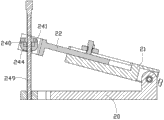
Fig. 2 is the three-dimensional view of level compensating tool of the present invention.
Fig. 3 is the decomposition view of level compensating tool of the present invention.
Fig. 4 is the cutaway view of level compensating tool of the present invention.
Fig. 5 is the cutaway view after level compensating tool of the present invention is adjusted.
Main element symbol description
| |
2 |
| |
1 |
| |
3 |
| |
4 |
| |
20 |
| The seat of |
21 |
| |
22 |
| Fixed |
23 |
| |
24 |
| Base |
201 |
| |
203 |
| The |
202 |
| Base the |
204 |
| Opening | 205 |
| The |
206 |
| The |
233 |
| The |
232 |
| The 3rd rotating |
231 |
| Seat of honour |
211 |
| |
214 |
| The |
215 |
| |
213 |
| The seat of honour the |
212 |
| |
217 |
| The second |
216 |
| The first |
25 |
| The |
26 |
| The first |
251 |
| Adjust plate |
221 |
| Adjust plate the |
222 |
| Bolt opening | 223 |
| The |
224 |
| |
27 |
| |
28 |
| The |
29 |
| |
272 |
| |
271 |
| The bolt seat of |
241 |
| |
244 |
| Bolt bearing | 240 |
| |
249 |
| Shaft bearing | 252 |
| The |
242 |
| The |
246 |
| The |
243 |
| The second through |
248 |
| |
253 |
| The 4th rotating |
245 |
| The first through |
247 |
The following specific embodiment further illustrates the present invention in connection with above-mentioned accompanying drawing.
The specific embodiment
Please refer to shown in Fig. 1 to Fig. 3, is a kind of level compensating tool 2.Described level compensating tool 2 is for compensating the angle between an elevating mechanism 1 and the product pressure head 3 of horizontal positioned.This product pressure head 3 is below for placing a product 4.Described level compensating tool 2 comprises that level is placed in base 20 on product pressure head 3, is rotationally connected with the seat of honour 21 on base 20, is movably connected on adjustment plate 22 on the seat of honour 21, is rotationally connected with the fixed block 23 on base 20 and is movably connected on fixed block 23 and adjusts the bolt mechanism 24 between plate 22.In the time utilizing described level compensating tool 2 to compensate the angle between elevating mechanism 1 and product pressure head 3, user orders about the described seat of honour 21 and rotates until the described seat of honour 21 is parallel with elevating mechanism 1 relative to base 20 by applying an external force, then adjust the distance of plate 22 on the seat of honour 21 until described bolt mechanism 24 is fixed on fixed block 23 and adjusts between plate 22, realize with this effect that reaches described elevating mechanism 1 horizontal pressing product pressure head 3 by described level compensating tool 2.
In order better to understand the present invention, below concrete structure and motion matching relationship to the present invention's each element in a specific embodiment be described in detail.
The outstanding protuberance 203 that is formed with in centre of described base first end 201.In present embodiment, the upper surface of described protuberance 203 is oval.Described protuberance 203 offers the first axis hole 202 in horizontal direction.Described base the second end 204 offers an opening 205 in centre position.Described opening 205 is for accommodating described bolt mechanism 24.Described base the second end 204 offers two the 4th axis holes 206 in both sides.
Described fixed block 23 offers the 5th axis hole 233 of aiming at the 4th axis hole 206 in horizontal direction.Described fixed block 23 offers the first perforation 232 in vertical direction.
Described level compensating tool 2 also comprises the 3rd rotating shaft 231.Described the 3rd rotating shaft 231 is rotationally connected with base the second end 204 through the 4th axis hole 206 and the 5th axis hole 233 by described fixed block 23.
The centre of described seat of honour first end 211 is formed with one for accommodating the depressed part 214 of protuberance 203.The both sides of described seat of honour first end 211 offer the second axis hole 215 of aiming at the first axis hole 202.In present embodiment, described the second axis hole 215 be shaped as trapezoidal shape.Described seat of honour first end 211 offers two Triaxial holes 213 in the two ends of depressed part 214.The described seat of honour the second end 212 is provided with a groove 217 and offers two the second blind holes 216 in upper surface.
Described level compensating tool 2 also comprises the first rotating shaft 25 and two the first screws 26.In described the first rotating shaft 25, offer first blind hole 251 of aiming at two Triaxial holes 213.Described the first rotating shaft 25 is rotationally connected with the seat of honour 21 on base 20 through the second axis hole 215 and the first axis hole 202.Two the first blind holes 251 that described two the first screws 26 are conflicted in described the first rotating shaft 25 through Triaxial hole 213 are to be fixed to the first rotating shaft 25 angle that fixes the described seat of honour 21 relative bases 20 in the second axis hole 215.In the present embodiment, the aperture of this second axis hole 215 reduces to the second end 212 directions of the seat of honour successively along seat of honour first end 211, when this first rotating shaft 25 moves up to a certain degree along the second axis hole 215 to the side of the seat of honour the second end 212 under the conflict of the first screw 26, cannot in the second axis hole 215, rotate because the restriction in these the second axis hole 215 apertures will cause this first rotating shaft 25, fix thus the angle of the described seat of honour 21 relative bases 20.
Described adjustment plate first end 221 is movably placed in groove 217.Described adjustment plate the second end 222 offers a bolt opening 223 and offers two the 6th axis holes 224 in both sides in centre position.
Described level compensating tool 2 also comprises and is placed in the latch segment 27 adjusted on plate 22, is placed in lock shaft 28 and two the second screws 29 on latch segment 27.On described latch segment 27, offer two screw hole 272 and slits 271 of aiming at the second blind hole 216.Described two the second screws 29 are fixed on latch segment 27 on the seat of honour 21 through screw hole 272 and the second blind hole 216, and described lock shaft 28 is fixed in the groove 217 at the seat of honour 21 adjusting plate 22 through slit 271.
Described bolt mechanism 24 is positioned in bolt opening 223.Described bolt mechanism 24 comprises the bolt seat of honour 241, be fixed on bolt base 244 under the bolt seat of honour 241, be placed in bolt bearing 240, strand fixing bolt 249 and two shaft bearings 252 on bolt base 244.On the described bolt seat of honour 241, have the second perforation 242.On described bolt base 244, offer the 7th axis hole 246 aimed at the 6th axis hole 224 and with offer the 8th axis hole 243 being communicated with the 7th axis hole 246 in upper surface.On described strand fixing bolt 249, offer one second through hole 248.On described shaft bearing 252, offer a dead eye 253.Described shaft bearing 252 is arranged between bolt base 244 and bolt opening 223 sidewalls.
Described level compensating tool 2 also includes the 4th rotating shaft 245.In the middle of described the 4th rotating shaft 245, offer the first through hole 247.Described strand fixing bolt 249 is fixed on described bolt mechanism 24 to adjust plate 22 and fixed block 23 through described the second perforation 242, the 8th axis hole 243, bolt bearing 240 and the first perforation 232.Described the 4th rotating shaft 245 is rotationally connected with bolt base 244 to adjust plate the second end 222 through the 6th axis hole 224, dead eye 253 and the 7th axis hole 246.
Please refer to shown in Fig. 4 to Fig. 5, in the time that the angle between elevating mechanism 1 and product pressure head 3 changes, first user will twist fixing bolt 249 and take out from bolt base 244 and fixed block 23 rotations, two the first screws 26 are taken out from the first blind hole 251 and Triaxial hole 213 to the restriction of removing the first rotating shaft 25, the angle of adjusting between the seat of honour 21 and base 20 makes this seat of honour 21 be parallel to elevating mechanism 1, then by two the first screws 26 conflict the position of this first rotating shaft 25 in the second axis hole 215 until this first rotating shaft 25 cannot in the second axis hole 215, rotate, the angle of fixing these seat of honour 21 relative bases 20 with this, adjust the distance of this adjustment plate 22 on the seat of honour 21 and adjust bolt base 244 angle until this strand fixing bolt 249 be just in time fixed between bolt base 244 and fixed block 23, make this elevating mechanism 1 of support that this level compensating tool 2 can be stable compensate the angle between this elevating mechanism 1 and the product pressure head 3 of level with this, realize this product pressure head 3 of pressing that this elevating mechanism 1 can level.In this process, also can these strand fixing bolt 249 out of plumb be fixed between 244 of bolt bases and fixed block 23 by the angle of adjusting fixed block 23 relative bases 20, also can realize identical effect.
Claims (6)
1. a level compensating tool, described level compensating tool is for compensating the angle between the product pressure head of an elevating mechanism and horizontal positioned, it is characterized in that: described level compensating tool comprises that level is placed in the base on product pressure head, be rotationally connected with the seat of honour on base, be movably connected on the adjustment plate on the seat of honour, be rotationally connected with the fixed block on base and be movably connected on fixed block and adjust the bolt mechanism between plate, rotate until the described seat of honour is parallel with elevating mechanism relative to base under external force at the described seat of honour, described adjustment plate under external force relatively seat of honour adjustment until described bolt mechanism be fixed between fixed block and adjustment plate.
2. level compensating tool as claimed in claim 1, it is characterized in that: the outstanding protuberance that forms in centre of described base first end, described protuberance offers the first axis hole in horizontal direction, the centre of described seat of honour first end is formed with one for accommodating the depressed part of protuberance, the both sides of described seat of honour first end offer the second axis hole of aiming at the first axis hole, described seat of honour first end offers two Triaxial holes in the two ends of depressed part, described level compensating tool also comprises the first rotating shaft and two the first screws, in described the first rotating shaft, offer first blind hole of aiming at two Triaxial holes, described the first rotating shaft is rotationally connected with the seat of honour on base through the second axis hole and the first axis hole, two the first blind holes that described two the first screws are conflicted in described the first rotating shaft through Triaxial hole are to be fixed to the first rotating shaft the angle that fixes the relative base in the described seat of honour in the second axis hole.
3. level compensating tool as claimed in claim 2, is characterized in that: described the second axis hole be shaped as trapezoidal shape.
4. level compensating tool as claimed in claim 1, it is characterized in that: the described seat of honour the second end is provided with a groove and offers two the second symmetrical blind holes in upper surface, the first end of described adjustment plate is movably placed in groove, described level compensating tool also comprises the latch segment being placed on adjustment plate, be placed in lock shaft and two the second screws on latch segment, on described latch segment, offer two screw hole and slits of aiming at the second blind hole, described two the second screws are fixed on latch segment on the seat of honour through screw hole and the second blind hole, described lock shaft is fixed in the groove at the seat of honour adjusting plate through slit.
5. level compensating tool as claimed in claim 1, it is characterized in that: described base the second end offers an opening in centre position, described base the second end offers the 4th axis hole in both sides, described fixed block offers the 5th axis hole of aiming at the 4th axis hole in horizontal direction, described level compensating tool also comprises the 3rd rotating shaft, and described the 3rd rotating shaft is rotationally connected with base the second end through the 4th axis hole and the 5th axis hole by described fixed block.
6. level compensating tool as claimed in claim 5, it is characterized in that: described fixed block offers one first perforation in vertical direction, described adjustment plate the second end offers a bolt opening and offers two the 6th axis holes in both sides in centre position, described bolt mechanism is positioned in bolt opening, described bolt mechanism comprises the bolt seat of honour, be fixed on the bolt base under the bolt seat of honour, be placed in the bolt bearing on bolt base, strand fixing bolt and two shaft bearings, described bolt has the second perforation on the seat of honour, on described bolt base, offer with the 6th axis hole aim at the 7th axis hole and with offer the 8th axis hole being communicated with the 7th axis hole in upper surface, on described shaft bearing, offer a dead eye, described shaft bearing is arranged between bolt base and bolt opening sidewalls, described level compensating tool also includes the 4th rotating shaft, in the middle of described the 4th rotating shaft, offer the first through hole, on described strand fixing bolt, offer one second through hole, described strand fixing bolt is through described the second perforation, the 8th axis hole, bolt bearing and the first perforation are fixed on described bolt mechanism to adjust between plate and fixed block, described the 4th rotating shaft is through the 6th axis hole, dead eye and the 7th axis hole are rotationally connected with bolt base to adjust plate the second end.
Priority Applications (3)
| Application Number | Priority Date | Filing Date | Title |
|---|---|---|---|
| CN201210542225.0A CN103862698A (en) | 2012-12-14 | 2012-12-14 | Horizontal compensating jig |
| TW101149439A TW201422384A (en) | 2012-12-14 | 2012-12-24 | Level compensating fixture |
| US13/972,864 US20140165860A1 (en) | 2012-12-14 | 2013-08-21 | Level compensation device |
Applications Claiming Priority (1)
| Application Number | Priority Date | Filing Date | Title |
|---|---|---|---|
| CN201210542225.0A CN103862698A (en) | 2012-12-14 | 2012-12-14 | Horizontal compensating jig |
Publications (1)
| Publication Number | Publication Date |
|---|---|
| CN103862698A true CN103862698A (en) | 2014-06-18 |
Family
ID=50901999
Family Applications (1)
| Application Number | Title | Priority Date | Filing Date |
|---|---|---|---|
| CN201210542225.0A Pending CN103862698A (en) | 2012-12-14 | 2012-12-14 | Horizontal compensating jig |
Country Status (3)
| Country | Link |
|---|---|
| US (1) | US20140165860A1 (en) |
| CN (1) | CN103862698A (en) |
| TW (1) | TW201422384A (en) |
Cited By (1)
| Publication number | Priority date | Publication date | Assignee | Title |
|---|---|---|---|---|
| CN108906978A (en) * | 2018-08-02 | 2018-11-30 | 安徽远都机床股份有限公司 | The press machine and working method of inclination is adjusted in a kind of high-performance |
Families Citing this family (1)
| Publication number | Priority date | Publication date | Assignee | Title |
|---|---|---|---|---|
| CN104118133B (en) * | 2014-07-29 | 2016-09-14 | 中核苏阀横店机械有限公司 | Adjustable die |
-
2012
- 2012-12-14 CN CN201210542225.0A patent/CN103862698A/en active Pending
- 2012-12-24 TW TW101149439A patent/TW201422384A/en unknown
-
2013
- 2013-08-21 US US13/972,864 patent/US20140165860A1/en not_active Abandoned
Cited By (2)
| Publication number | Priority date | Publication date | Assignee | Title |
|---|---|---|---|---|
| CN108906978A (en) * | 2018-08-02 | 2018-11-30 | 安徽远都机床股份有限公司 | The press machine and working method of inclination is adjusted in a kind of high-performance |
| CN108906978B (en) * | 2018-08-02 | 2019-12-03 | 安徽远都机床股份有限公司 | The press machine and working method of inclination is adjusted in a kind of high-performance |
Also Published As
| Publication number | Publication date |
|---|---|
| TW201422384A (en) | 2014-06-16 |
| US20140165860A1 (en) | 2014-06-19 |
Similar Documents
| Publication | Publication Date | Title |
|---|---|---|
| CN104033535B (en) | A kind of three-dimensional vibration isolating device being applicable to low-frequency vibration | |
| RU2009105951A (en) | TROLLEY FOR SLIDING CONSOLE DOORS AND METHOD OF ITS MANUFACTURE | |
| CN103862698A (en) | Horizontal compensating jig | |
| CN103410869A (en) | Adjustable bearing pedestal device | |
| CN106932199B (en) | A kind of internal messing variable tooth thickness gear testing stand | |
| US9205523B2 (en) | Positioning apparatus | |
| CN105739610A (en) | All-in-one machine | |
| CN104302145A (en) | Slide rail | |
| CN203532548U (en) | Adjustable bearing pedestal device | |
| CN204611253U (en) | Four connection-rod support | |
| CN202835212U (en) | Angle-adjustable mounting part and lamp using same | |
| CN105149908A (en) | Gear press-fitting clamp | |
| CN203082469U (en) | Support seat assembly for testing drive axle assemblies | |
| CN202998721U (en) | Display screen angle adjusting device with fine tuning structure | |
| CN205166328U (en) | Gear press -mounting fixture | |
| CN205184923U (en) | Perforating device | |
| CN103195865B (en) | Supporting device and supporting simulation test table thereof | |
| CN103287073B (en) | A kind of method realizing PCB and steel mesh rapid-aligning in printing machine | |
| CN203762641U (en) | Nineteen-inch sliding rail free of tool installation | |
| CN103134650B (en) | Measurement jig | |
| CN205746470U (en) | The automobile shot-light repacking lossless mounting bracket of lamp | |
| KR101264025B1 (en) | Device for assembling pitch rod assembly | |
| CN205333938U (en) | Adjustable mirror holder of two dimension based on curved surface location | |
| CN202840282U (en) | Fine adjustment support of cabinet door and power distribution cabinet with fine adjustment support of cabinet door | |
| JP2018021666A (en) | Eccentric pin |
Legal Events
| Date | Code | Title | Description |
|---|---|---|---|
| C06 | Publication | ||
| PB01 | Publication | ||
| C02 | Deemed withdrawal of patent application after publication (patent law 2001) | ||
| WD01 | Invention patent application deemed withdrawn after publication |
Application publication date: 20140618 |