CN103801987A - Method for improving precision of numerically-controlled machine tool main shaft rotating thermal error measuring data - Google Patents
Method for improving precision of numerically-controlled machine tool main shaft rotating thermal error measuring data Download PDFInfo
- Publication number
- CN103801987A CN103801987A CN201410063872.2A CN201410063872A CN103801987A CN 103801987 A CN103801987 A CN 103801987A CN 201410063872 A CN201410063872 A CN 201410063872A CN 103801987 A CN103801987 A CN 103801987A
- Authority
- CN
- China
- Prior art keywords
- check rod
- machine tool
- thermal error
- data
- thermal deformation
- Prior art date
- Legal status (The legal status is an assumption and is not a legal conclusion. Google has not performed a legal analysis and makes no representation as to the accuracy of the status listed.)
- Pending
Links
- 238000000034 method Methods 0.000 title claims abstract description 21
- 238000006073 displacement reaction Methods 0.000 claims description 19
- 238000004364 calculation method Methods 0.000 claims description 5
- 238000005070 sampling Methods 0.000 claims 2
- 230000005144 thermotropism Effects 0.000 claims 2
- 238000005259 measurement Methods 0.000 abstract description 23
- 230000000694 effects Effects 0.000 abstract description 5
- 230000007547 defect Effects 0.000 abstract description 4
- 238000013178 mathematical model Methods 0.000 abstract description 4
- 238000003672 processing method Methods 0.000 abstract description 2
- 238000004088 simulation Methods 0.000 abstract description 2
- 238000012360 testing method Methods 0.000 description 41
- 238000007689 inspection Methods 0.000 description 25
- 238000000691 measurement method Methods 0.000 description 5
- 238000005516 engineering process Methods 0.000 description 3
- XEEYBQQBJWHFJM-UHFFFAOYSA-N Iron Chemical compound [Fe] XEEYBQQBJWHFJM-UHFFFAOYSA-N 0.000 description 2
- 238000004458 analytical method Methods 0.000 description 1
- 230000009286 beneficial effect Effects 0.000 description 1
- 238000004422 calculation algorithm Methods 0.000 description 1
- 238000013480 data collection Methods 0.000 description 1
- 238000010586 diagram Methods 0.000 description 1
- 229910052742 iron Inorganic materials 0.000 description 1
- 239000000463 material Substances 0.000 description 1
- 238000012545 processing Methods 0.000 description 1
- 230000035945 sensitivity Effects 0.000 description 1
Images


Classifications
-
- B—PERFORMING OPERATIONS; TRANSPORTING
- B23—MACHINE TOOLS; METAL-WORKING NOT OTHERWISE PROVIDED FOR
- B23Q—DETAILS, COMPONENTS, OR ACCESSORIES FOR MACHINE TOOLS, e.g. ARRANGEMENTS FOR COPYING OR CONTROLLING; MACHINE TOOLS IN GENERAL CHARACTERISED BY THE CONSTRUCTION OF PARTICULAR DETAILS OR COMPONENTS; COMBINATIONS OR ASSOCIATIONS OF METAL-WORKING MACHINES, NOT DIRECTED TO A PARTICULAR RESULT
- B23Q17/00—Arrangements for observing, indicating or measuring on machine tools
Landscapes
- Engineering & Computer Science (AREA)
- Mechanical Engineering (AREA)
- Automatic Control Of Machine Tools (AREA)
Abstract
本发明公开了一种数控机床主轴旋转热误差测量数据精度的提升方法,对主轴旋转产生的在主轴X和Y向热误差进行了原理性分析计算,对测量数据进行了修正,获得了更加准确的实际热误差数据,避免了现有技术所存在的原理性误差,获得实际的机床主轴X和Y向热误差,保证了依据该数据建立的数学模型具有更高的精度。本发明修正了传统数控机床主轴旋转热误差测量数据处理方法中原理性缺陷,获得了精确的机床主轴热误差测量数据,避免了因根据原理性缺陷数据建立的模型补偿仿真精度与实际补偿功效差异过大的缺点,保证了数控机床热误差补偿建模精度的真实有效性,增强了热误差补偿功能与精度,可通过软件编程实现在线准确测量数据的获取,具有实用性。
The invention discloses a method for improving the accuracy of measurement data accuracy of the spindle rotation thermal error of a numerically controlled machine tool. The thermal errors generated by the spindle rotation in the X and Y directions of the spindle are analyzed and calculated in principle, and the measurement data is corrected to obtain more accurate results. The actual thermal error data avoids the principle error existing in the prior art, obtains the actual thermal error of the machine tool spindle in the X and Y directions, and ensures that the mathematical model established based on the data has higher accuracy. The present invention corrects the principle defect in the data processing method of the traditional CNC machine tool spindle rotation thermal error measurement, obtains accurate machine tool spindle thermal error measurement data, and avoids the excessive difference between the model compensation simulation accuracy and the actual compensation effect caused by the principle defect data The big shortcoming ensures the true validity of the thermal error compensation modeling accuracy of CNC machine tools, enhances the thermal error compensation function and accuracy, and can realize the acquisition of online accurate measurement data through software programming, which is practical.
Description
技术领域 technical field
本发明涉及数控机床热误差补偿精度提升技术领域,具体涉及一种数控机床主轴旋转热误差测量数据精度的提升方法。 The invention relates to the technical field of improving the accuracy of thermal error compensation of a numerical control machine tool, in particular to a method for improving the accuracy of measurement data of the thermal error of the spindle rotation of a numerical control machine tool.
背景技术 Background technique
数控机床主轴旋转热误差补偿技术在实施时,补偿量是依据已建立的数学模型计算后获得。数学模型来源于实验数据,准确的实验数据对数控机床热误差补偿效果与相关的热误差分析结论具有重要的影响。目前主轴热变形实验数据获得是依据国标《机床检验通则 第3部分:热效应的确定(GB/T 17421.3-2009)》提供方法,将位移传感器布置在主轴检验棒X、Y和Z向(其中X和Y处于同一圆截面上),根据传感器数值变动量作为主轴X、Y 和Z向热误差数值。但是,数控机床主轴发生热变形后,主轴热变形方式多样,包括偏移、翘曲等多种形式,这导致了主轴检验棒圆心位置发生变化,而传感器的空间位置并没有随之变动,此时测出的数据并非通过检验棒圆心位置的X、Y和Z向的检验棒上点的位移量,而是正对传感器方向的检验棒表面点到传感器的位移量。实质热变形量应该是通过检验棒圆心位置的X、Y和Z向的检验棒上点的位移变化量,这造成了目前进行数控机床主轴热误差测量时存在数据处理技术上的原理性误差(其中Z向造成的误差较小,本专利不予考虑)。 When the thermal error compensation technology of the spindle rotation of the CNC machine tool is implemented, the compensation amount is obtained after calculation based on the established mathematical model. The mathematical model comes from the experimental data, and the accurate experimental data has an important influence on the thermal error compensation effect of the CNC machine tool and the related thermal error analysis conclusion. At present, the experimental data of the thermal deformation of the spindle is obtained according to the method provided by the national standard "General Rules for Machine Tool Inspection Part 3: Determination of Thermal Effects (GB/T 17421.3-2009)", and the displacement sensors are arranged in the X, Y and Z directions of the spindle inspection rod (where X and Y are on the same circular section), according to the variation of the sensor value as the thermal error value of the main axis X, Y and Z. However, after the thermal deformation of the spindle of the CNC machine tool, the thermal deformation of the spindle is various, including offset, warping and other forms, which leads to the change of the center position of the spindle test rod, but the spatial position of the sensor does not change accordingly. The measured data is not the displacement of the point on the test rod in the X, Y and Z directions passing through the center of the test rod, but the displacement from the point on the surface of the test rod facing the sensor direction to the sensor. The actual amount of thermal deformation should be the displacement change of the point on the test rod in the X, Y and Z directions of the center of the test rod, which causes the principle error of data processing technology in the current measurement of the thermal error of the spindle of the CNC machine tool ( Among them, the error caused by the Z direction is small, which is not considered in this patent).
发明内容 Contents of the invention
本发明要解决的技术问题是提供一种数控机床主轴旋转热误差测量数据精度的提升方法,避免现有技术所存在的原理性误差,获得实际的机床主轴X和Y向热误差,保证依据该数据建立的数学模型具有更高的精度。 The technical problem to be solved by the present invention is to provide a method for improving the accuracy of the measurement data accuracy of the thermal error of the spindle rotation of the CNC machine tool, to avoid the principle error existing in the prior art, to obtain the actual thermal error of the spindle of the machine tool in the X and Y directions, and to ensure that based on the The mathematical model established by the data has higher precision.
本发明的技术方案如下: Technical scheme of the present invention is as follows:
一种数控机床主轴旋转热误差测量数据精度的提升方法,其方法具体包括以下步骤: A method for improving the accuracy of measurement data of a spindle rotation thermal error of a numerically controlled machine tool, the method specifically comprising the following steps:
(1)、针对数控机床主轴检验棒,在通过检验棒圆心位置的X和Y向同一圆截面方向上安置两个精密位移传感器(接触或非接触式),用于测量传感器距离通过检验棒圆心位置的X和Y向的检验棒上点的位移变化。在机床主轴发生热变形前,检验棒半径为R,检验棒圆心坐标O(0,0),测量检验棒X向点坐标A(x0,0)(x0=R)和Y向点坐标B(0,y0)(y0=R),如图1所示; (1) For the inspection rod of the spindle of the CNC machine tool, two precision displacement sensors (contact or non-contact) are placed on the X and Y directions of the same circular section passing through the center of the inspection rod to measure the distance between the sensors and the center of the inspection rod. The position X and Y direction of the displacement change of the point on the check rod. Before the thermal deformation of the main shaft of the machine tool, the radius of the inspection rod is R, the coordinates of the center of the inspection rod are O (0,0), and the coordinates of the X-direction point A (x 0,0 ) (x 0 =R) and Y-direction point coordinates of the inspection rod are measured B(0,y 0 )(y 0 =R), as shown in Figure 1;
(2)、数控机床主轴热变形后,第一次进行热变形数据采样,由于主轴检验棒发生了偏移等热变形,主轴检验棒圆心由原来的O点移动到O’(x’, y’)点位置,此时通过检验棒圆心位置的X和Y向的检验棒上点已变动到A1和B1处,如图1所示。而两个精密位移传感器测量检验棒X向和Y向点坐标分别为A’(x1,0)和B’(0,y1),此时A’和B’并非为通过检验棒圆心位置的X和Y向的检验棒上点。因检验棒半径为R,根据公式: (2) After the thermal deformation of the spindle of the CNC machine tool, the thermal deformation data is sampled for the first time. Due to thermal deformation such as offset of the spindle inspection rod, the center of the spindle inspection rod moves from the original O point to O'(x', y ') point position, at this time, the points on the test rod in the X and Y directions passing through the center of the test rod have changed to A1 and B1, as shown in Figure 1. The two precision displacement sensors measure the coordinates of the X-direction and Y-direction points of the test rod as A' (x 1 , 0) and B' (0, y 1 ) respectively. At this time, A' and B' are not the positions of the center of the test rod. Points on the X and Y directions of the inspection stick. Because the radius of the test rod is R, according to the formula:
(1) (1)
由公式(1)解得(x’, y’)有两组解: Solving (x’, y’) from formula (1) has two sets of solutions:


由于检验棒圆心的偏移量是微米级,相对初始圆心O(0,0)的改变也属于微米级,故选择公式(3)作为检验棒偏移后的圆心坐标O’(x’, y’); Since the offset of the center of the test rod is at the micron level, the change relative to the initial center O(0,0) is also at the micron level, so formula (3) is selected as the center coordinate O'(x', y) of the test rod after offset ');
确定出检验棒圆心坐标O’(x’, y’)后,反算出通过检验棒圆心位置的X和Y向的检验棒上点坐标为A1(xA1,yA1)和B1(xB1,yB1)。式中: After determining the coordinates O'(x', y') of the center of the test rod, the coordinates of the point on the test rod in the X and Y directions passing through the center of the test rod are calculated as A1 (x A1 , y A1 ) and B1 (x B1 , y B1 ). In the formula:

(5) (5)
(3)、主轴热变形计算按照以下公式计算: (3) The thermal deformation calculation of the main shaft is calculated according to the following formula:
X向热变形为:△x1=xA1-x0(x0=R); X-direction thermal deformation is: △x 1 =x A1 -x 0 (x 0 =R);
Y向热变形为:△y1= yB1-y0(y0=R); The thermal deformation in the Y direction is: △y 1 = y B1 -y 0 (y 0 =R);
即: Right now:
(6) (6)
(4)、依此类推,当第N次进行热变形数据采样时,两个精密位移传感器测量检验棒X向和Y向点坐标分别为AN(xN,0)和BN(0,yN),根据公式(3)确定出检验棒圆心坐标为ON(xN, yN)。根据公式(4)、(5)反算出通过检验棒圆心位置的X和Y向的检验棒上点坐标为AN(xAN, yAN)和BN(xBN, yBN)。根据步骤(3)计算: (4), and so on, when the thermal deformation data is sampled for the Nth time, the coordinates of the X-direction and Y-direction points of the test rod measured by the two precision displacement sensors are A N (x N ,0) and B N (0, y N ), according to the formula (3), the coordinates of the center of the test bar are determined as O N (x N , y N ). According to the formulas (4) and (5), the coordinates of the points on the test rod in the X and Y directions passing through the center of the test rod are calculated as AN (x AN , y AN ) and BN (x BN , y BN ). Calculate according to step (3):
X向热变形为:△xN=xAN-x0(x0=R); X-direction thermal deformation is: △x N =x AN -x 0 (x 0 =R);
Y向热变形为:△yN= yBN-y0(y0=R); The thermal deformation in the Y direction is: △y N = y BN -y 0 (y 0 =R);
即: Right now:

本发明的有益效果: Beneficial effects of the present invention:
(1)、本发明修正了传统数控机床主轴旋转热误差测量数据处理方法中原理性缺陷,获得了精确的机床主轴热误差测量数据; (1), the present invention corrects the principle defect in the traditional CNC machine tool spindle rotation thermal error measurement data processing method, and obtains accurate machine tool spindle thermal error measurement data;
(2)、本发明避免了因根据原理性缺陷数据建立的模型补偿仿真精度与实际补偿功效差异过大的缺点,保证了数控机床热误差补偿建模精度的真实有效性,增强了热误差补偿功能与精度; (2) The present invention avoids the disadvantage that the simulation accuracy of the model compensation established based on the principle defect data is too large and the actual compensation effect is too large, ensures the authenticity and effectiveness of the modeling accuracy of the thermal error compensation of the CNC machine tool, and enhances the thermal error compensation function and precision;
(3)、本发明方法使用简便、稳定性高、可靠性强,可通过软件编程实现在线准确测量数据的获取,具有很好的实用性。 (3) The method of the present invention is easy to use, high in stability, and strong in reliability, and can realize online accurate measurement data acquisition through software programming, and has good practicability.
附图说明 Description of drawings
图1为测量误差原理示意图。 Figure 1 is a schematic diagram of the measurement error principle.
图2为新型测量X向热误差数据与传统测量X向热误差数据比较图。 Figure 2 is a comparison chart of the new measurement X-direction thermal error data and the traditional measurement X-direction thermal error data.
图3为新型测量Y向热误差数据与传统测量Y向热误差数据比较图。 Figure 3 is a comparison chart of the new measurement Y-direction thermal error data and the traditional measurement Y-direction thermal error data.
具体实施方式 Detailed ways
参见图1,一种数控机床主轴旋转热误差测量数据精度的提升方法,具体包括以下步骤: Referring to Fig. 1, a method for improving the accuracy of the measurement data of the thermal error of the spindle rotation of the CNC machine tool, specifically includes the following steps:
(1)、针对数控机床主轴检验棒,在通过检验棒圆心位置的X和Y向同一圆截面方向上安置两个精密位移传感器(接触或非接触式),用于测量传感器距离通过检验棒圆心位置的X和Y向的检验棒上点的位移变化。在机床主轴发生热变形前,检验棒半径为R,检验棒圆心坐标O(0,0),测量检验棒X向点坐标A(x0,0)(x0=R)和Y向点坐标B(0,y0)(y0=R),如图1所示; (1) For the inspection rod of the spindle of the CNC machine tool, two precision displacement sensors (contact or non-contact) are placed on the X and Y directions of the same circular section passing through the center of the inspection rod to measure the distance between the sensors and the center of the inspection rod. The position X and Y direction of the displacement change of the point on the check rod. Before the thermal deformation of the main shaft of the machine tool, the radius of the inspection rod is R, the coordinates of the center of the inspection rod are O (0,0), and the coordinates of the X-direction point A (x 0,0 ) (x 0 =R) and Y-direction point coordinates of the inspection rod are measured B(0,y 0 )(y 0 =R), as shown in Figure 1;
(2)、数控机床主轴热变形后,第一次进行热变形数据采样,由于主轴检验棒发生了偏移等热变形,主轴检验棒圆心由原来的O点移动到O’(x’, y’)点位置,此时通过检验棒圆心位置的X和Y向的检验棒上点已变动到A1和B1处,如图1所示。而两个精密位移传感器测量检验棒X向和Y向点坐标分别为A’(x1,0)和B’(0,y1),此时A’和B’并非为通过检验棒圆心位置的X和Y向的检验棒上点。因检验棒半径为R,根据公式: (2) After the thermal deformation of the spindle of the CNC machine tool, the thermal deformation data is sampled for the first time. Due to thermal deformation such as offset of the spindle inspection rod, the center of the spindle inspection rod moves from the original O point to O'(x', y ') point position, at this time, the points on the test rod in the X and Y directions passing through the center of the test rod have changed to A1 and B1, as shown in Figure 1. The two precision displacement sensors measure the coordinates of the X-direction and Y-direction points of the test rod as A' (x 1 , 0) and B' (0, y 1 ) respectively. At this time, A' and B' are not the positions of the center of the test rod. Points on the X and Y directions of the inspection stick. Because the radius of the test rod is R, according to the formula:

由公式(1)解得(x’, y’)有两组解: Solving (x’, y’) from formula (1) has two sets of solutions:


由于检验棒圆心的偏移量是微米级,相对初始圆心O(0,0)的改变也属于微米级,故选择公式(3)作为检验棒偏移后的圆心坐标O’(x’, y’); Since the offset of the center of the test rod is at the micron level, the change relative to the initial center O(0,0) is also at the micron level, so formula (3) is selected as the center coordinate O'(x', y) of the test rod after offset ');
确定出检验棒圆心坐标O’(x’, y’)后,反算出通过检验棒圆心位置的X和Y向的检验棒上点坐标为A1(xA1,yA1)和B1(xB1,yB1)。式中: After determining the coordinates O'(x', y') of the center of the test rod, the coordinates of the point on the test rod in the X and Y directions passing through the center of the test rod are calculated as A1 (x A1 , y A1 ) and B1 (x B1 , y B1 ). In the formula:


(3)、主轴热变形计算按照以下公式计算: (3) The thermal deformation calculation of the main shaft is calculated according to the following formula:
X向热变形为:△x1=xA1-x0(x0=R); X-direction thermal deformation is: △x 1 =x A1 -x 0 (x 0 =R);
Y向热变形为:△y1= yB1-y0(y0=R); The thermal deformation in the Y direction is: △y 1 = y B1 -y 0 (y 0 =R);
即: Right now:

(4)、依此类推,当第N次进行热变形数据采样时,两个精密位移传感器测量检验棒X向和Y向点坐标分别为AN(xN,0)和BN(0,yN),根据公式(3)确定出检验棒圆心坐标为ON(xN, yN)。根据公式(4)、(5)反算出通过检验棒圆心位置的X和Y向的检验棒上点坐标为AN(xAN, yAN)和BN(xBN, yBN)。根据步骤(3)计算: (4), and so on, when the thermal deformation data is sampled for the Nth time, the coordinates of the X-direction and Y-direction points of the test rod measured by the two precision displacement sensors are A N (x N ,0) and B N (0, y N ), according to the formula (3), the coordinates of the center of the test bar are determined as O N (x N , y N ). According to the formulas (4) and (5), the coordinates of the points on the test rod in the X and Y directions passing through the center of the test rod are calculated as AN (x AN , y AN ) and BN (x BN , y BN ). Calculate according to step (3):
X向热变形为:△xN=xAN-x0(x0=R); X-direction thermal deformation is: △x N =x AN -x 0 (x 0 =R);
Y向热变形为:△yN= yBN-y0(y0=R); The thermal deformation in the Y direction is: △y N = y BN -y 0 (y 0 =R);
即: Right now:

参见图2、图3,以下通过具体实施方式对本发明作进一步说明: Referring to Fig. 2, Fig. 3, the present invention will be further described below through specific embodiment:
本实施例中,选用: In this embodiment, choose:
(1)、南通科技(TONTEC)VCL850型号的立式数控加工中心,出厂指标是:X轴行程:850 mm;Y轴行程:550 mm;Z轴行程:540 mm;工作台面积:550*1000 mm;主轴最高转速:8000 rpm;主轴孔锥度:BT-40;X/Y/Z轴快速位移:36 m/min;最大切削进给率:24 m/min;定位精度:0.01 mm;重复定位精度:0.005 mm; (1), Nantong Science and Technology ( TONTEC ) VCL850 vertical CNC machining center, the factory index is: X-axis stroke: 850 mm; Y-axis stroke: 550 mm; Z-axis stroke: 540 mm; worktable area: 550*1000 mm; maximum spindle speed: 8000 rpm; spindle hole taper: BT-40; X/Y/Z axis rapid displacement: 36 m/min; maximum cutting feed rate: 24 m/min; positioning accuracy: 0.01 mm; repeat positioning Accuracy: 0.005mm;
(2)、圆检验棒,指标是:材料:铁;长度:30 cm;半径:10 mm;上端面锥度:BT-40;下端面:平面; (2) The indicators of the round test rod are: material: iron; length: 30 cm; radius: 10 mm; upper end face taper: BT-40; lower end face: plane;
(3)、KAMAN公司KD2306-1SM型号的电涡流传感器,出厂指标是:量程范围:0.001~1.000mm(本试验选择测量范围为:0.250~0.350mm);标准灵敏度:10V/mm;分辨率:0.1mm;测量精度:1mm;频率响应:50 KHz;电压:24V。 (3) For the KD2306-1SM eddy current sensor of KAMAN company, the factory index is: measuring range: 0.001~1.000mm (this test chooses measuring range: 0.250~0.350mm); standard sensitivity: 10V/mm; resolution: 0.1mm; measurement accuracy: 1mm; frequency response: 50 KHz; voltage: 24V.
测量使用时,主轴旋转转速固定为3000 rpm,采集系统每隔3 min采集一次测量数据,主轴旋转时间持续5 h以上。 When measuring, the rotation speed of the spindle is fixed at 3000 rpm, and the acquisition system collects measurement data every 3 minutes, and the rotation time of the spindle lasts for more than 5 hours.
方法步骤如下: The method steps are as follows:
(1)、针对数控机床主轴检验棒,在通过检验棒圆心位置的X和Y向同一圆截面方向上安置两个精密电涡流位移传感器,用于测量传感器距离通过检验棒圆心位置的X和Y向的检验棒上点的位移变化。在机床主轴旋转发生热变形前,检验棒半径为R=10000 mm,检验棒圆心坐标O(0,0),测量检验棒X向点坐标A(R,0)和Y向点坐标B(0,R); (1) For the inspection rod of the spindle of the CNC machine tool, two precision eddy current displacement sensors are placed in the direction of X and Y passing through the center of the inspection rod in the direction of the same circular section to measure the distance between the sensors and X and Y passing through the center of the inspection rod The displacement change of the point on the check rod. Before the thermal deformation of the main shaft of the machine tool occurs, the radius of the inspection rod is R=10000 mm, the center coordinate of the inspection rod is O (0,0), and the X-direction point coordinate A (R, 0) and the Y-direction point coordinate B (0 ,R);
(2)、数控机床主轴以3000 rpm旋转3 min之后进行第一次热变形数据采集,测得两个电涡流传感器测量检验棒X向和Y向的偏移量为


(1) (1)
(3)、依此类推,当第N次进行热变形数据采集时,测得两个电涡流传感器测量检验棒X向和Y向的偏移量为


即: Right now:

(4)、数控机床主轴以3000 rpm旋转,持续时间为330 min,共采集获得110组热误差数据,X向传统热误差数据为数组[2.7200,9.6880,14.3200,17.8080,18.7620,20.8560,21.1440,22.5960,……,10.8860,10.8920,11.1740,9.7280,11.1740,9.5960,9.6300,10.2900] (单位:mm),Y向传统热误差数据为数组[5.0800,12.8820,19.3160,22.7560,23.7120,24.8320,24.2820,28.8880,……,8.6620,7.8300,8.2280,7.6400,5.9940,7.4880,7.3180,7.5220] (单位:mm)。依据计算公式(2)可以获得新型测量方法的热误差数据,X向新型热误差数据为数组[2.7071,9.6056,14.1354,17.5525,18.4849,20.5529,20.8544,22.1857,……,10.8490,10.8618,11.1407,9.6992,11.1564,9.5683,9.6036,10.2621] (单位:mm),Y向新型热误差数据为数组[5.0763,12.8359,19.2161,22.6019,23.5411,24.6208,24.0645,28.6419,……,8.6031,7.7710,8.1659,7.5930,5.9318,7.4422,7.2719,7.4693] (单位:mm)。 (4) The spindle of the CNC machine tool rotates at 3000 rpm for a duration of 330 minutes. A total of 110 sets of thermal error data are collected. The traditional thermal error data in the X direction is an array [2.7200, 9.6880, 14.3200, 17.8080, 18.7620, 20.8560, 21.1440, 22.5960,……, 10.8860, 10.8920, 11.1740, 9.7280, 11.1740, 9.5960, 9.6300, 10.2900] (unit: mm), Y-direction traditional thermal error data is an array [5.0800, 12.8820, 19.3160, 22.7560, 23.408, 2 28.8880,..., 8.6620, 7.8300, 8.2280, 7.6400, 5.9940, 7.4880, 7.3180, 7.5220] (unit: mm). According to the calculation formula (2), the thermal error data of the new measurement method can be obtained. The new thermal error data in the X direction is an array [2.7071, 9.6056, 14.1354, 17.5525, 18.4849, 20.5529, 20.8544, 22.1857, ..., 10.8490, 10.8618, 11.1407, 9.6992, 11.1564, 9.5683, 9.6036, 10.2621] (unit: mm), the new thermal error data in the Y direction is an array [5.0763, 12.8359, 19.2161, 22.6019, 23.5411, 24.6208, 24.0645, 28.6419, ..., 8.67131, 95, 7 7.5930, 5.9318, 7.4422, 7.2719, 7.4693] (unit: mm).
新型测量数据精度的提升方法与传统测量数据精度算法比较: Comparison of the new measurement data accuracy improvement method with the traditional measurement data accuracy algorithm:
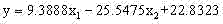
(1)、将新型提升方法测量的热误差数据与传统方法测量的热误差数据分别进行多项式数据拟合,建立热误差与温度之间的数学关系。新型提升方法测量的X向热误差数据拟合的多项式为
(2)、分析比较其结果,数控机床主轴旋转热误差测量数据精度的提升方法获得的热误差数据比传统的热误差数据更加准确,同时,新型测量数据精度的提升方法与传统测量数据精度算法相比较,数据拟合精度更高,效果更好。 (2) Analyzing and comparing the results, the thermal error data obtained by the method of improving the accuracy of the thermal error measurement data of the spindle rotation of the CNC machine tool is more accurate than the traditional thermal error data. In comparison, the data fitting accuracy is higher and the effect is better.
Claims (1)


Priority Applications (1)
| Application Number | Priority Date | Filing Date | Title |
|---|---|---|---|
| CN201410063872.2A CN103801987A (en) | 2014-02-25 | 2014-02-25 | Method for improving precision of numerically-controlled machine tool main shaft rotating thermal error measuring data |
Applications Claiming Priority (1)
| Application Number | Priority Date | Filing Date | Title |
|---|---|---|---|
| CN201410063872.2A CN103801987A (en) | 2014-02-25 | 2014-02-25 | Method for improving precision of numerically-controlled machine tool main shaft rotating thermal error measuring data |
Publications (1)
| Publication Number | Publication Date |
|---|---|
| CN103801987A true CN103801987A (en) | 2014-05-21 |
Family
ID=50699626
Family Applications (1)
| Application Number | Title | Priority Date | Filing Date |
|---|---|---|---|
| CN201410063872.2A Pending CN103801987A (en) | 2014-02-25 | 2014-02-25 | Method for improving precision of numerically-controlled machine tool main shaft rotating thermal error measuring data |
Country Status (1)
| Country | Link |
|---|---|
| CN (1) | CN103801987A (en) |
Cited By (7)
| Publication number | Priority date | Publication date | Assignee | Title |
|---|---|---|---|---|
| CN105058163A (en) * | 2015-05-11 | 2015-11-18 | 西安理工大学 | Device and method for measuring thermal error at working state of gear grinding machine |
| CN105241382A (en) * | 2015-10-16 | 2016-01-13 | 合肥工业大学 | Time grating rotary table thermal error measuring system and measurement calculating method thereof |
| CN109483326A (en) * | 2017-09-12 | 2019-03-19 | 哈恩和特斯基工件指数有限商业两合公司 | Method in lathe by location of the core on geometrical axis |
| CN112902848A (en) * | 2021-01-19 | 2021-06-04 | 重庆理工大学 | Z-direction linear displacement and error measurement method and system of three-axis numerical control machine tool |
| CN113251909A (en) * | 2021-06-25 | 2021-08-13 | 清华大学 | Calibration device and method of eddy current sensor for measuring displacement of rotating shaft |
| CN113341878A (en) * | 2021-06-23 | 2021-09-03 | 重庆理工大学 | Thermal error measuring method of five-axis numerical control machine tool |
| CN114012505A (en) * | 2021-11-12 | 2022-02-08 | 湖北文理学院 | A method and system for calibrating a machine tool spindle |
-
2014
- 2014-02-25 CN CN201410063872.2A patent/CN103801987A/en active Pending
Cited By (12)
| Publication number | Priority date | Publication date | Assignee | Title |
|---|---|---|---|---|
| CN105058163A (en) * | 2015-05-11 | 2015-11-18 | 西安理工大学 | Device and method for measuring thermal error at working state of gear grinding machine |
| CN105058163B (en) * | 2015-05-11 | 2017-08-25 | 西安理工大学 | Thermal Error measurement apparatus and measuring method during gear grinding machines working condition |
| CN105241382A (en) * | 2015-10-16 | 2016-01-13 | 合肥工业大学 | Time grating rotary table thermal error measuring system and measurement calculating method thereof |
| CN105241382B (en) * | 2015-10-16 | 2017-09-26 | 合肥工业大学 | When grid turntable Thermal Error measuring system Thermal Error survey calculation method |
| CN109483326A (en) * | 2017-09-12 | 2019-03-19 | 哈恩和特斯基工件指数有限商业两合公司 | Method in lathe by location of the core on geometrical axis |
| CN109483326B (en) * | 2017-09-12 | 2021-09-10 | 哈恩和特斯基工件指数有限商业两合公司 | Method for positioning a center point on a geometric axis in a machine tool |
| CN112902848A (en) * | 2021-01-19 | 2021-06-04 | 重庆理工大学 | Z-direction linear displacement and error measurement method and system of three-axis numerical control machine tool |
| CN113341878A (en) * | 2021-06-23 | 2021-09-03 | 重庆理工大学 | Thermal error measuring method of five-axis numerical control machine tool |
| CN113341878B (en) * | 2021-06-23 | 2023-04-18 | 重庆理工大学 | Thermal error measuring method of five-axis numerical control machine tool |
| CN113251909A (en) * | 2021-06-25 | 2021-08-13 | 清华大学 | Calibration device and method of eddy current sensor for measuring displacement of rotating shaft |
| CN114012505A (en) * | 2021-11-12 | 2022-02-08 | 湖北文理学院 | A method and system for calibrating a machine tool spindle |
| CN114012505B (en) * | 2021-11-12 | 2022-12-13 | 湖北文理学院 | Method and system for correcting machine tool spindle |
Similar Documents
| Publication | Publication Date | Title |
|---|---|---|
| CN103801987A (en) | Method for improving precision of numerically-controlled machine tool main shaft rotating thermal error measuring data | |
| CN109032070B (en) | A non-contact R-test measuring instrument calibration method using eddy current displacement sensor | |
| CN109032069B (en) | A method for calculating spherical center coordinates of non-contact R-test measuring instrument using eddy current displacement sensor | |
| CN102785128B (en) | The part processing precision on-line detecting system of NC Machine lathe and detection method | |
| US10422619B2 (en) | Identification of geometric deviations of a motion guide in a coordinate-measuring machine or in a machine tool | |
| CN113446968B (en) | Method for detecting and identifying installation error of main shaft and coaxiality of main shaft and C axis | |
| CN108445835B (en) | A Method for Part Machining Dimension Prediction of CNC Machine Tool | |
| CN105397549B (en) | The small change point methods of machine tooling hole face workpiece | |
| CN105571461A (en) | Accuracy measurement method for precision tapered hole | |
| CN102001024A (en) | Measuring method for in-site measurement of free-form curved surface based on machining machine tool | |
| CN103659467B (en) | The scaling method of the axial pretravel of touch trigger probe | |
| CN110375698A (en) | Inner hole circularity on-position measure method based on parameter identification | |
| CN102259278A (en) | Method for detecting geometric form and position tolerance of parts on line | |
| CN109253710B (en) | Calibration method for zero error of A axis of REVO measuring head | |
| CN112846936A (en) | Method for calibrating accuracy of trigger type measuring head in on-machine detection | |
| CN205209415U (en) | Accurate taper hole NULL device | |
| CN108919746B (en) | A thermal error test and analysis method for a swing table | |
| CN108332642B (en) | Right-angle head precision detection method | |
| Maščeník et al. | Determining the exact value of the shape deviations of the experimental measurements | |
| CN107900781B (en) | Calibration device and calibration method of contact online detection system for lathes | |
| CN108534676B (en) | A method for checking the spatial error in the measurement space of a coordinate measuring machine | |
| CN207982928U (en) | The caliberating device of contact on-line detecting system for lathe | |
| CN107957254A (en) | Measure the experimental provision of numerically controlled machine Instantaneous center and definite method | |
| CN110017803A (en) | A kind of REVO gauge head B axle error of zero scaling method | |
| CN106989661A (en) | A kind of method for testing lathe hydrostatic slideway surface shape error |
Legal Events
| Date | Code | Title | Description |
|---|---|---|---|
| C06 | Publication | ||
| PB01 | Publication | ||
| WD01 | Invention patent application deemed withdrawn after publication | ||
| WD01 | Invention patent application deemed withdrawn after publication |
Application publication date: 20140521 |