CN103735237A - Water tank cleaner - Google Patents
Water tank cleaner Download PDFInfo
- Publication number
- CN103735237A CN103735237A CN201310749864.9A CN201310749864A CN103735237A CN 103735237 A CN103735237 A CN 103735237A CN 201310749864 A CN201310749864 A CN 201310749864A CN 103735237 A CN103735237 A CN 103735237A
- Authority
- CN
- China
- Prior art keywords
- draining
- water
- drainboard
- area
- tank body
- Prior art date
- Legal status (The legal status is an assumption and is not a legal conclusion. Google has not performed a legal analysis and makes no representation as to the accuracy of the status listed.)
- Granted
Links
Images


Classifications
-
- A—HUMAN NECESSITIES
- A47—FURNITURE; DOMESTIC ARTICLES OR APPLIANCES; COFFEE MILLS; SPICE MILLS; SUCTION CLEANERS IN GENERAL
- A47L—DOMESTIC WASHING OR CLEANING; SUCTION CLEANERS IN GENERAL
- A47L15/00—Washing or rinsing machines for crockery or tableware
- A47L15/0086—In-sink dishwashers
-
- A—HUMAN NECESSITIES
- A47—FURNITURE; DOMESTIC ARTICLES OR APPLIANCES; COFFEE MILLS; SPICE MILLS; SUCTION CLEANERS IN GENERAL
- A47J—KITCHEN EQUIPMENT; COFFEE MILLS; SPICE MILLS; APPARATUS FOR MAKING BEVERAGES
- A47J43/00—Implements for preparing or holding food, not provided for in other groups of this subclass
- A47J43/24—Devices for washing vegetables or the like
-
- A—HUMAN NECESSITIES
- A47—FURNITURE; DOMESTIC ARTICLES OR APPLIANCES; COFFEE MILLS; SPICE MILLS; SUCTION CLEANERS IN GENERAL
- A47L—DOMESTIC WASHING OR CLEANING; SUCTION CLEANERS IN GENERAL
- A47L15/00—Washing or rinsing machines for crockery or tableware
- A47L15/42—Details
- A47L15/4202—Water filter means or strainers
- A47L15/4204—Flat filters
-
- A—HUMAN NECESSITIES
- A47—FURNITURE; DOMESTIC ARTICLES OR APPLIANCES; COFFEE MILLS; SPICE MILLS; SUCTION CLEANERS IN GENERAL
- A47L—DOMESTIC WASHING OR CLEANING; SUCTION CLEANERS IN GENERAL
- A47L15/00—Washing or rinsing machines for crockery or tableware
- A47L15/42—Details
- A47L15/4214—Water supply, recirculation or discharge arrangements; Devices therefor
- A47L15/4225—Arrangements or adaption of recirculation or discharge pumps
-
- Y—GENERAL TAGGING OF NEW TECHNOLOGICAL DEVELOPMENTS; GENERAL TAGGING OF CROSS-SECTIONAL TECHNOLOGIES SPANNING OVER SEVERAL SECTIONS OF THE IPC; TECHNICAL SUBJECTS COVERED BY FORMER USPC CROSS-REFERENCE ART COLLECTIONS [XRACs] AND DIGESTS
- Y02—TECHNOLOGIES OR APPLICATIONS FOR MITIGATION OR ADAPTATION AGAINST CLIMATE CHANGE
- Y02B—CLIMATE CHANGE MITIGATION TECHNOLOGIES RELATED TO BUILDINGS, e.g. HOUSING, HOUSE APPLIANCES OR RELATED END-USER APPLICATIONS
- Y02B40/00—Technologies aiming at improving the efficiency of home appliances, e.g. induction cooking or efficient technologies for refrigerators, freezers or dish washers
Landscapes
- Engineering & Computer Science (AREA)
- Water Supply & Treatment (AREA)
- Mechanical Engineering (AREA)
- Food Science & Technology (AREA)
- Sink And Installation For Waste Water (AREA)
- Structures Of Non-Positive Displacement Pumps (AREA)
- Detail Structures Of Washing Machines And Dryers (AREA)
- Washing And Drying Of Tableware (AREA)
- Cleaning By Liquid Or Steam (AREA)
Abstract
本发明公开了一种水槽式清洗机,包括形成洗涤空间的箱体,所述箱体包括水槽本体,其特征在于,所述水槽本体至少在中央部位下凹,下凹的部位上覆盖有与下凹部位形状相同的沥水板,所述沥水板上开设有多个用于沥水的沥水孔,所述下凹的部位和沥水板之间的空间形成沥水区域,所述沥水板与水槽本体底部其他部位齐平,所述沥水区域内设有将该沥水区域的水泵出到沥水板上方的水泵。将水泵设置在水槽本体的沥水区域内,对水泵的补水效果好,出水部件的设置方便,并能获得较好的喷淋效果;通过将沥水板中央的宽度设置成大于两侧的宽度,可以保证中心的水泵能均匀地接受各个侧面的进水。
The invention discloses a sink type cleaning machine, which comprises a box body forming a washing space, the box body including a sink body, characterized in that the sink body is concave at least in the central part, and the concave part is covered with A draining plate with the same shape in the concave part, the draining plate is provided with a plurality of draining holes for draining, the space between the concave part and the draining plate forms a draining area, and the draining plate and the bottom of the sink body Other parts are flush, and a water pump is provided in the draining area to pump the water in the draining area to the top of the draining plate. The water pump is set in the draining area of the sink body, which has a good water replenishment effect on the water pump, convenient setting of the water outlet parts, and better spraying effect; by setting the width of the center of the draining plate to be greater than the width of both sides, it can Make sure the center pump receives water evenly from all sides.
Description
技术领域technical field
本发明涉及一种清洗机,尤其是一种水槽式清洗机。The invention relates to a washing machine, in particular to a sink type washing machine.
背景技术Background technique
洗碗机是一种将冷水或热水喷射到盘碟以清除粘附在盘碟上的脏物并且清洗盘碟的装置。将盘碟放置在洗碗柜内的盘碟框中,一般的洗碗机包括喷射洗涤水的泵和喷头,产生热水的加热器等。现今的洗碗机中已经开始使用蒸汽来清洗盘碟,与使用加热的水相比,利用蒸汽也更加减少了洗涤的时间,以及提高了洗涤的效果。这些洗碗机都具有一个共同的缺点,即是所需要的空间较大,这样的洗碗机通常需要自身独立的外壳以及独立的部件,因此一般的洗碗机的体积都较大,不适用于一些人口众多、人均居住面积较小的家庭的使用,因此在很多家庭,洗碗机的使用也不是很普遍。A dishwasher is a device that sprays cold or hot water onto dishes to remove dirt adhering to the dishes and to clean the dishes. The dishes are placed in the dish frame in the dishwashing cabinet. A general dishwasher includes a pump and a nozzle for spraying washing water, a heater for generating hot water, and the like. Today's dishwashers have begun to use steam to clean dishes. Compared with using heated water, using steam can also reduce the washing time and improve the washing effect. These dishwashers all have a common shortcoming, that is, the required space is relatively large, and such dishwashers usually require their own independent casing and independent parts, so the general dishwashers are relatively large in size and are not suitable for use. It is used in some families with a large population and a small living area per capita, so in many families, the use of dishwashers is not very common.
为了节约空间,现已出现了不少水槽式的清洗机设计,即将现有的水槽改装为清洗机,直接以水槽作为洗涤空间,一般都在水槽底部设置一旋转喷臂,该旋转喷臂通常连接一由电机驱动的泵体。如申请号为200880003431.6的中国专利申请《具有洗碗设备的厨房水槽及其所用的洗涤水喷洒设备》所公开的,其洗涤水喷洒设备安装在水槽盆处,从而喷洒碗碟所用的洗涤水,所述设备包括:喷洒头,该喷洒头具有喷洒孔,这些喷洒孔用于喷洒由供水泵供应的加压洗涤水,从而洗涤借助格架布置在所述水槽盘的底部上的碗碟;禁固装置,该紧固装置用于以可旋转的方式接收所述喷洒头,以将该喷洒头安装在所述水槽盆的底部;旋转驱动装置,该旋转驱动装置借助于所述供水泵供应的加压洗涤水操作,并安装成使所述喷洒头旋转;开闭件,该开闭件上下运动,从而在非洗涤操作期间关闭所述喷洒头的所述喷洒孔以防止从所述水槽盆回流,并且在洗涤操作期间打开所述喷洒头的喷洒孔;以及用于使所述开闭件上下运动的上下装置。In order to save space, there have been many sink-type washing machine designs, that is, the existing sink is converted into a washing machine, and the sink is directly used as the washing space. Generally, a rotating spray arm is arranged at the bottom of the sink. Connect a pump driven by a motor. As disclosed in the Chinese patent application "Kitchen Sink with Dishwashing Equipment and Washing Water Spraying Equipment" with application number 200880003431.6, the washing water spraying equipment is installed at the sink basin to spray the washing water used for dishes, The device comprises: a spray head having spray holes for spraying pressurized wash water supplied by a water supply pump to wash the dishes arranged on the bottom of the sink tray by means of a grid; means for rotatably receiving the sprinkler head to mount the sprinkler head on the bottom of the sink basin; rotational drive means for adding water supplied by the water supply pump; pressurized wash water operation and mounted to rotate said sprinkler head; a shutter that moves up and down to close said spray hole of said sprinkler head during non-washing operations to prevent backflow from said sink basin , and opening the spray hole of the spray head during washing operation; and an up and down device for moving the opening and closing member up and down.
在这类水槽式清洗机中,旋转喷臂和泵体都设置在洗涤区域,水泵直接从洗涤区域中补水,其因而所补的水不可避免地会带有油污和/或食物的残渣,从而影响水泵的工作效率和使用寿命;另一方面,水泵补水需要一定的水位高度,由于整个水槽底部都是补水区域,因而水槽底部面积越大,需要的洗涤用水量就越大,而在洗涤过程中必须维持一定的洗涤剂浓度,所以所需要的洗涤剂也就越多,从而造成浪费,也不环保。In this type of sink type cleaning machine, the rotating spray arm and the pump body are all arranged in the washing area, and the water pump directly replenishes water from the washing area, so that the replenished water will inevitably contain oil stains and/or food residues, thereby Affect the working efficiency and service life of the water pump; on the other hand, the water replenishment of the water pump requires a certain water level height. Since the bottom of the entire sink is a water replenishment area, the larger the area of the bottom of the sink, the greater the amount of washing water required, and in the washing process A certain concentration of detergent must be maintained in the washing machine, so the more detergent is needed, which causes waste and is not environmentally friendly.
发明内容Contents of the invention
本发明所要解决的技术问题是针对上述现有技术的问题,提供一种在洗涤过程中能有效阻止食物残渣进入水泵的水槽式清洗机。The technical problem to be solved by the present invention is to provide a sink type cleaning machine which can effectively prevent food residues from entering the water pump during the washing process.
本发明所要解决的另一个技术问题是提供一种能有效减少洗涤用水量而不影响水泵补水的水槽式清洗机。Another technical problem to be solved by the present invention is to provide a sink type washing machine that can effectively reduce the amount of washing water without affecting the water replenishment of the water pump.
本发明解决上述技术问题所采用的技术方案为:一种水槽式清洗机,包括形成洗涤空间的箱体,所述箱体包括水槽本体,其特征在于,所述水槽本体至少在中央部位下凹,下凹的部位上覆盖有与下凹部位形状相同的沥水板,所述沥水板上开设有多个用于沥水的沥水孔,所述下凹的部位和沥水板之间的空间形成沥水区域,所述沥水板与水槽本体底部其他部位齐平,所述沥水区域内设有将该沥水区域的水泵出到沥水板上方的水泵。The technical solution adopted by the present invention to solve the above technical problems is: a sink type cleaning machine, including a box body forming a washing space, the box body includes a sink body, and the feature is that the sink body is concave at least in the central part , the concave part is covered with a draining plate with the same shape as the concave part, and the draining plate is provided with a plurality of draining holes for draining, and the space between the concave part and the draining plate forms a draining area , the draining plate is flush with other parts of the bottom of the sink body, and a water pump is provided in the draining area to pump the water in the draining area to the top of the draining plate.
为了可在水槽本体的沥水区域外设置其他部件如超声波发生装置等,优选的,所述水槽本体仅在中央部位下凹,下凹的部位由所述水槽本体的底板形成,或者由水槽本体的底板缺失一部分,缺失的部分下方设置盒体形成。In order to arrange other components such as ultrasonic generators etc. outside the draining area of the tank body, preferably, the tank body is only concave in the central part, and the concave part is formed by the bottom plate of the tank body, or formed by the bottom plate of the tank body. A part of the bottom plate is missing, and a box is formed under the missing part.
为了使得水泵四周进水均匀,所述沥水板呈长条形、长圆形或椭圆形,沥水板的中央区域的宽度大于位于中央区域两侧的翼部区域的宽度。In order to make water inflow evenly around the water pump, the drain plate is in the shape of a strip, oblong or oval, and the width of the central area of the drain plate is greater than the width of the wing areas located on both sides of the central area.
所述中央区域的中心开设有供水泵穿过的安装孔,沥水板上环绕安装孔的部分设置有环形的封闭区域,所述封闭区域上不开设沥水孔,使得水从沥水板上方到水泵之间具有一定的加速距离,并且有助于水泵形成负压,以获得更好的汲水效果。The center of the central area is provided with a mounting hole through which the water supply pump passes, and an annular closed area is provided on the part surrounding the mounting hole on the draining plate. No draining hole is set on the closed area, so that the water flows from the top of the draining plate to the water pump. There is a certain acceleration distance between them, and it helps the water pump to form a negative pressure to obtain a better water pumping effect.
为了增加沥水区域的盛水量,从沥水区域喷出去的水在返回时路径较短,使得进水更均匀,从而更有利于清洗,优选的,所述沥水板沿水槽本体底部的对角线延伸。In order to increase the water holding capacity of the draining area, the water sprayed from the draining area has a shorter path when returning, so that the water intake is more uniform, which is more conducive to cleaning. Preferably, the draining plate is along the diagonal line at the bottom of the tank body extend.
为了简化水泵的结构,使得水泵的制造工艺也较为简单,优选的,所述水泵为开放式水泵,所述水泵包括叶轮和导流支架,所述叶轮包括末端与电机的输出轴连接的中空的轴和多个在轴周面上均匀分布并且沿轴向延伸的叶片,所述导流支架中心形成有容置所述叶片下段的下容置空腔,所述导流支架的底面与水槽本体的底部之间具有间隔。In order to simplify the structure of the water pump and make the manufacturing process of the water pump relatively simple, preferably, the water pump is an open water pump. Shaft and a plurality of vanes that are evenly distributed on the peripheral surface of the shaft and extend in the axial direction. A lower accommodating cavity for accommodating the lower section of the vane is formed in the center of the flow guide bracket. The bottom surface of the flow guide bracket is in contact with the tank body There is a gap between the bottom of the .
为了便于清洗,沥水板与导流支架的优选的连接方式为,所述导流支架的顶部从安装孔露出于沥水板,导流支架的下容置空腔的外周具有下台阶面,所述沥水板位于安装孔周围的部分搁置于下台阶面上。In order to facilitate cleaning, the preferred connection mode between the drain board and the flow guide bracket is that the top of the drain guide bracket is exposed from the installation hole on the drain board, and the outer periphery of the lower accommodation cavity of the drain guide bracket has a lower step surface, and the The part of the drain board positioned around the mounting hole rests on the lower step surface.
与现有技术相比,本发明的优点在于:通过设置覆盖有沥水板的沥水区域,并将水泵设置在沥水区域内,从而将水泵与洗涤区域相隔离,使回流到水泵中的水先经过沥水板的过滤,从而提高的水泵的工作效率和使用寿命;而仅在水槽本体底部的中央部位设置下凹的沥水区域,使得无论水槽本体底部面积多大,沥水区域都保持相同的存水量,从而有效地节省了洗涤用水和洗涤剂;通过将沥水板中央的宽度设置成大于两侧的宽度,可以保证中心的水泵能均匀地接受各个侧面的进水,同时在节水的前提下也保证补水效果;水泵上方的沥水板部分不设置沥水孔,使得该部分的水到达水泵之前具有一定的加速距离,并且有助于水泵形成负压,以获得更好的汲水效果。Compared with the prior art, the present invention has the advantages of: by setting the draining area covered with the draining plate, and setting the water pump in the draining area, the water pump is isolated from the washing area, so that the water flowing back into the water pump passes through the draining area first. Plate filtration, thereby improving the working efficiency and service life of the water pump; and only setting a concave draining area at the center of the bottom of the tank body, so that no matter how large the bottom area of the tank body is, the draining area maintains the same water storage capacity, thus effectively Greatly saves washing water and detergent; by setting the width of the center of the drain plate to be greater than the width of both sides, it can ensure that the water pump in the center can evenly receive the water from all sides, and at the same time, it can also ensure the water replenishment effect under the premise of saving water ; The part of the drain plate above the water pump is not provided with a drain hole, so that the water in this part has a certain acceleration distance before reaching the water pump, and it helps the water pump to form a negative pressure to obtain a better water-drawing effect.
附图说明Description of drawings
图1为本发明的水槽式清洗机的示意图;Fig. 1 is the schematic diagram of tank type washing machine of the present invention;
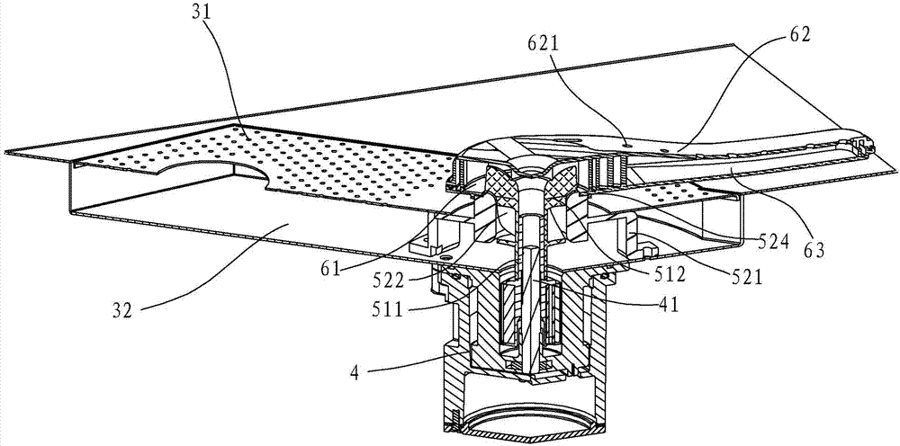
图2为本发明的水槽式清洗机的局部剖视图;Fig. 2 is a partial sectional view of the sink type washing machine of the present invention;
图3为本发明的沥水板和水泵的示意图;Fig. 3 is the schematic diagram of drain plate and water pump of the present invention;
图4为本发明的沥水板的一个可替代实施例的示意图;Fig. 4 is the schematic diagram of an alternative embodiment of the drain board of the present invention;
图5为本发明的沥水板的另一个可替代实施例的示意图。Fig. 5 is a schematic diagram of another alternative embodiment of the draining plate of the present invention.
具体实施方式Detailed ways
以下结合附图实施例对本发明作进一步详细描述。The present invention will be further described in detail below in conjunction with the accompanying drawings and embodiments.
参见图1-图3,一种水槽式清洗机,可以用于清洗碗碟、蔬菜、水果等,包括水槽本体1,以及转动连接在水槽本体1顶部的盖板2,水槽本体1可以为家用的普通水槽,水槽本体1和盖板2之间形成有洗涤空间,以容纳上述的碗碟、蔬菜、水果等,对其进行清洗。Referring to Fig. 1-Fig. 3, a sink type cleaning machine can be used to clean dishes, vegetables, fruits, etc., and includes a sink body 1, and a
水槽本体1的底板11至少在中央部位下凹,在底板11下凹部分的上方,间隔地覆盖有与下凹部分形状相同的沥水板3,沥水板3上开设有多个用于沥水的沥水孔31,沥水板3和底板11下凹部分之间间隔的空间形成沥水区域32,沥水板3与底板11的其他部分齐平。可替代的,沥水区域32的形成也可以为,底板11缺失一部分,缺失部分下方设有一盒体,沥水板3覆盖在盒体上方,并且与底板11的其他部分齐平,盒体和沥水板3之间的空间形成沥水区域32。或者,沥水板3可以与底板11的形状、大小相同,并且整个位于底板11上方,与底板11相间隔,沥水板3和底板11之间间隔出的空间形成沥水区域32。The
水槽本体1外侧,底板11的下方安装有电机4,电机4的输出轴41伸入到水槽本体1内后,位于底板11上方的沥水区域32内,或者,采用盒体时,电机4的输出轴41伸入到盒体上方的沥水区域32内。On the outside of the water tank body 1, a
沥水区域32内设置有水泵,与沥水板3上方的洗涤空间隔开,从而洗涤后回流到沥水区域32内混合有食物残渣的水可以先经过沥水板3过滤,以避免食物残渣进入到水泵5而堵塞水泵5,由此可提高水泵5的工作效率和使用寿命。在本实施例中,采用开放式水泵,水泵包括叶轮51,叶轮51包括位于中心的中空轴511以及多个设置在轴511周面上的叶片512,叶片512在轴511的周面上均匀分布并且沿轴向延伸,轴511的下端与电机4的输出轴41连接,由此电机4转动时可带动叶轮51转动。A water pump is arranged in the
叶轮51外设置有导流支架52,导流支架52周向上设有多个安装支脚521,可通过螺钉等将安装支脚521与底板11、盒体或电机4固定,导流支架52的底面与沥水区域32的底面之间具有间隔,以供沥水区域32内的水流通过。叶片512的下部位于导流支架52中心形成的下容置空腔522内,上部露出于导流支架52。The
优选的,导流支架52的顶部露出于沥水板3,沥水板3与导流支架52相对应的位置开设有安装孔33,供导流支架52或叶片512上部穿过。因此,该叶轮51至少部分露出于沥水板3而位于沥水板3上方。导流支架52中心的下容置空腔522的外周具有下台阶面523,与沥水板3的下表面抵接,沥水板3位于安装孔33周围的部分搁置于下台阶面523上。导流支架52也可以全部位于沥水区域32内。Preferably, the top of the
沥水区域32呈长条形并且端部由两侧向中间倾斜形成一尖角,沿水槽本体1底部的对角线延伸。相应地,沥水板3的形状与沥水区域32的形状一致。沥水板3的中央区域34的宽度大于位于中央区域34两侧的翼部区域35的宽度,安装孔33位于沥水板3的中央区域34的中心,沥水板3环绕安装孔33的部分设置有环形的封闭区域36,该封闭区域36上不设有沥水孔31。由于沥水板3两侧的翼部区域35进水较多,因此,中央区域34的增大的宽度可以保证叶轮51四周的进水量保持均匀。而封闭区域36的设置,使得水流不能从安装孔33周围直接进入到沥水区域32内的叶轮51周围,而需要绕到封闭区域36的外围进入到沥水区域32,由此使得从沥水板3的中央区域34经过,到达沥水区域32的水与叶轮51之间具有一定的距离,使得水流具有一定的加速距离,并且有助于形成负压,使得叶轮51的汲水效果较好,可以顺利地从沥水区域32泵出。The
参见图4,沥水板的一个可替代的实施例,本实施例与上述实施例的不同之处在于沥水板3’呈椭圆形,同样的,其中央区域34’的宽度也大于翼部区域35’的宽度;参见图5,沥水板的另一个可替代的实施例,本实施例与上述实施例的不同之处在于沥水板3’’呈长圆形,同样的,其中央区域34’’的宽度也大于翼部区域35’’的宽度。Referring to Fig. 4, an alternative embodiment of the drain board, the difference between this embodiment and the above-mentioned embodiment is that the
导流支架52的顶部支承有旋转喷臂6,旋转喷臂6位于沥水板3上方,其中间底部形成有上容置空腔61,以容纳叶片512的上部,导流支架52的下容置空腔522、叶轮51和上容置空腔61形成上述的水泵,用于将沥水区域32内的水泵出,通过旋转喷臂6对待清洗对象(上文所述的碗碟、蔬菜、水果等)进行冲洗。The top of the
旋转喷臂6包括上盖体62和下盖体63,两者之间形成与上容置空腔61连通的流道,上容置空腔61位于旋转喷臂6的中间,而流道位于上容置空腔61的两侧。上盖体62上表面开设有多个出水孔621,出水孔621位于流道的上方,与流道相对应,由水泵泵出的水通过上容置空腔61进入到流道,进而从出水孔621喷出,对待清洗对象进行冲洗。导流支架52上位于下台阶面523上方的位置处还设有上台阶面524,与旋转喷臂6的下表面抵接,旋转喷臂6搁置在上台阶面524上。The rotating
可替代的,水泵也可以采用常用的封闭式结构的水泵,沥水区域32内的水抽入到封闭式水泵内,并从出水口泵出到旋转喷臂6内,即旋转喷臂6仍作为封闭式水泵的出水部件。Alternatively, the water pump can also be a water pump with a commonly used closed structure. The water in the
沥水区域32内还设有渣篮321,渣篮321的上端穿过沥水板3,用于盛装清洗后的残渣,以避免堵塞与渣篮321连通的出水管道;底板11位于沥水板3周围的部位可设置超声波发生器112。Also be provided with
Claims (7)
Priority Applications (7)
| Application Number | Priority Date | Filing Date | Title |
|---|---|---|---|
| CN201310749864.9A CN103735237B (en) | 2013-12-31 | 2013-12-31 | Water tank cleaner |
| PCT/CN2014/001154 WO2015100700A1 (en) | 2013-12-31 | 2014-12-22 | Sink-type washing machine |
| US15/108,243 US10258216B2 (en) | 2013-12-31 | 2014-12-22 | Sink-type washing machine |
| CA2934977A CA2934977C (en) | 2013-12-31 | 2014-12-22 | Sink-type washing machine |
| JP2016544571A JP6407290B2 (en) | 2013-12-31 | 2014-12-22 | Sink type washing machine |
| MYPI2016001156A MY183630A (en) | 2013-12-31 | 2014-12-22 | Sink-type washing machine |
| KR1020167020793A KR101929866B1 (en) | 2013-12-31 | 2014-12-22 | Sink-type washing machine |
Applications Claiming Priority (1)
| Application Number | Priority Date | Filing Date | Title |
|---|---|---|---|
| CN201310749864.9A CN103735237B (en) | 2013-12-31 | 2013-12-31 | Water tank cleaner |
Publications (2)
| Publication Number | Publication Date |
|---|---|
| CN103735237A true CN103735237A (en) | 2014-04-23 |
| CN103735237B CN103735237B (en) | 2015-05-20 |
Family
ID=50492365
Family Applications (1)
| Application Number | Title | Priority Date | Filing Date |
|---|---|---|---|
| CN201310749864.9A Active CN103735237B (en) | 2013-12-31 | 2013-12-31 | Water tank cleaner |
Country Status (7)
| Country | Link |
|---|---|
| US (1) | US10258216B2 (en) |
| JP (1) | JP6407290B2 (en) |
| KR (1) | KR101929866B1 (en) |
| CN (1) | CN103735237B (en) |
| CA (1) | CA2934977C (en) |
| MY (1) | MY183630A (en) |
| WO (1) | WO2015100700A1 (en) |
Cited By (16)
| Publication number | Priority date | Publication date | Assignee | Title |
|---|---|---|---|---|
| WO2015100699A1 (en) * | 2013-12-31 | 2015-07-09 | 宁波方太厨具有限公司 | Rotating spray wall used in washing apparatus and application thereof |
| WO2015100701A1 (en) * | 2013-12-31 | 2015-07-09 | 宁波方太厨具有限公司 | Open water tank washing machine |
| WO2015100695A1 (en) * | 2013-12-31 | 2015-07-09 | 宁波方太厨具有限公司 | Water tank washing machine |
| WO2015100700A1 (en) * | 2013-12-31 | 2015-07-09 | 宁波方太厨具有限公司 | Sink-type washing machine |
| CN105167729A (en) * | 2015-09-21 | 2015-12-23 | 马信芳 | Box structure of dish washing machine |
| CN105545790A (en) * | 2016-02-29 | 2016-05-04 | 宁波方太厨具有限公司 | Open water pump and water tank groove cleaning machine with same |
| CN106037607A (en) * | 2016-07-04 | 2016-10-26 | 宁波市天马厨具有限公司 | Dishwasher heating device |
| CN106618419A (en) * | 2016-12-02 | 2017-05-10 | 宁波方太厨具有限公司 | Water channel cleaning machine cleaning with turbulent flow |
| CN109288086A (en) * | 2018-11-09 | 2019-02-01 | 宁波美高厨具有限公司 | Sink and water tank cleaner |
| CN109875480A (en) * | 2019-04-02 | 2019-06-14 | 周小波 | A water pump and a dishwasher |
| CN110448207A (en) * | 2019-07-11 | 2019-11-15 | 宁波方太厨具有限公司 | A kind of fruit-vegetable cleaner |
| CN111227741A (en) * | 2018-11-29 | 2020-06-05 | 宁波方太厨具有限公司 | Box structure of cleaning machine |
| CN111657818A (en) * | 2019-03-06 | 2020-09-15 | 宁波方太厨具有限公司 | a cleaning machine |
| CN111657807A (en) * | 2019-03-06 | 2020-09-15 | 宁波方太厨具有限公司 | Cleaning machine |
| CN111657764A (en) * | 2019-03-06 | 2020-09-15 | 宁波方太厨具有限公司 | Cleaning machine |
| CN113520261A (en) * | 2020-04-14 | 2021-10-22 | 宁波方太厨具有限公司 | Cleaning machine |
Families Citing this family (7)
| Publication number | Priority date | Publication date | Assignee | Title |
|---|---|---|---|---|
| KR20180088205A (en) * | 2017-01-26 | 2018-08-03 | 엘지전자 주식회사 | A sink |
| CN108451463B (en) * | 2017-08-04 | 2023-10-17 | 施贵平 | Cleaning machine |
| CN109394117B (en) * | 2017-08-18 | 2024-02-20 | 宁波方太厨具有限公司 | Spray arm and cleaning machine applying same |
| WO2019113160A1 (en) * | 2017-12-07 | 2019-06-13 | As America, Inc. | Self-cleaning sink |
| EP3530159B1 (en) * | 2018-02-21 | 2020-07-29 | Vorwerk & Co. Interholding GmbH | Food preparation device with releasable tool |
| CN109645858A (en) * | 2018-12-27 | 2019-04-19 | 浙江欧琳生活健康科技有限公司 | A kind of water tank type washing device |
| US11911719B2 (en) * | 2019-09-20 | 2024-02-27 | Massachusetts Institute Of Technology | Devices and methods for the integrated filtration, drying, and mechanical processing of active pharmaceutical ingredients |
Citations (6)
| Publication number | Priority date | Publication date | Assignee | Title |
|---|---|---|---|---|
| US4776359A (en) * | 1985-12-09 | 1988-10-11 | Federighi Jr George B | Under counter glass washer |
| DE19860186A1 (en) * | 1998-06-29 | 1999-12-30 | Aquis Gmbh Rebstein | Rinsing device has rinsing basin |
| CN2838527Y (en) * | 2005-11-22 | 2006-11-22 | 崔美娟 | Kitchen washing appliance |
| CN101600371A (en) * | 2007-01-29 | 2009-12-09 | 罗必灿 | Have the kitchen basin of dish-washing apparatus and used washing-water spray apparatus thereof |
| CN102125417A (en) * | 2010-12-23 | 2011-07-20 | 徐州工业职业技术学院 | Multifunctional water tank |
| CN203693523U (en) * | 2013-12-31 | 2014-07-09 | 宁波方太厨具有限公司 | Water tank type cleaning machine |
Family Cites Families (16)
| Publication number | Priority date | Publication date | Assignee | Title |
|---|---|---|---|---|
| US3312232A (en) * | 1965-01-22 | 1967-04-04 | Gen Electric | Pump impeller and reaction-type spray device having an inlet disposed in the same plane |
| US3709236A (en) * | 1969-12-08 | 1973-01-09 | Jenn Air Corp | Dishwasher |
| JPS5344725Y2 (en) * | 1974-10-07 | 1978-10-26 | ||
| SG126666A1 (en) * | 1991-12-20 | 2006-11-29 | Fisher & Paykel Appliances Ltd | Dishwasher |
| US5377707A (en) * | 1993-11-01 | 1995-01-03 | White Consolidated Industries, Inc. | Dishwasher pump and filtration system |
| US5779812A (en) * | 1995-08-25 | 1998-07-14 | Whirlpool Corporation | Multi-mesh mechanical filter screen system for dishwashers |
| US6182674B1 (en) * | 1996-11-19 | 2001-02-06 | Whirlpool Corporation | Pump and soil collection system for a dishwasher |
| US7201175B2 (en) * | 2002-05-03 | 2007-04-10 | Whirlpool Corporation | User interface for an in-sink dishwasher |
| CN2715690Y (en) * | 2004-08-13 | 2005-08-10 | 广西民族学院 | Dishware cleaning machine by supersonic wave and bi-directional jetting combined function |
| KR100694323B1 (en) * | 2005-01-25 | 2007-03-12 | 엘지전자 주식회사 | Screen filter fastening structure of dishwasher |
| JP2010516423A (en) * | 2007-01-29 | 2010-05-20 | チャン ナ,ピル | Dishwasher-integrated sink base and washing water jetting device therefor |
| TWI328862B (en) * | 2008-07-07 | 2010-08-11 | Au Optronics Corp | Method for fabricating pixel structure |
| US20100037923A1 (en) * | 2008-08-14 | 2010-02-18 | Whirlpool Corporation | Removable dishwasher filtration system |
| CN203709974U (en) * | 2013-06-05 | 2014-07-16 | 宁波方太厨具有限公司 | Rotary spraying arm for washing device and application of rotary spraying arm for washing device |
| CN103735237B (en) * | 2013-12-31 | 2015-05-20 | 宁波方太厨具有限公司 | Water tank cleaner |
| CN203693527U (en) * | 2013-12-31 | 2014-07-09 | 宁波方太厨具有限公司 | Lockable water tank type cleaning machine box |
-
2013
- 2013-12-31 CN CN201310749864.9A patent/CN103735237B/en active Active
-
2014
- 2014-12-22 WO PCT/CN2014/001154 patent/WO2015100700A1/en not_active Ceased
- 2014-12-22 MY MYPI2016001156A patent/MY183630A/en unknown
- 2014-12-22 US US15/108,243 patent/US10258216B2/en active Active
- 2014-12-22 CA CA2934977A patent/CA2934977C/en active Active
- 2014-12-22 KR KR1020167020793A patent/KR101929866B1/en active Active
- 2014-12-22 JP JP2016544571A patent/JP6407290B2/en active Active
Patent Citations (6)
| Publication number | Priority date | Publication date | Assignee | Title |
|---|---|---|---|---|
| US4776359A (en) * | 1985-12-09 | 1988-10-11 | Federighi Jr George B | Under counter glass washer |
| DE19860186A1 (en) * | 1998-06-29 | 1999-12-30 | Aquis Gmbh Rebstein | Rinsing device has rinsing basin |
| CN2838527Y (en) * | 2005-11-22 | 2006-11-22 | 崔美娟 | Kitchen washing appliance |
| CN101600371A (en) * | 2007-01-29 | 2009-12-09 | 罗必灿 | Have the kitchen basin of dish-washing apparatus and used washing-water spray apparatus thereof |
| CN102125417A (en) * | 2010-12-23 | 2011-07-20 | 徐州工业职业技术学院 | Multifunctional water tank |
| CN203693523U (en) * | 2013-12-31 | 2014-07-09 | 宁波方太厨具有限公司 | Water tank type cleaning machine |
Cited By (19)
| Publication number | Priority date | Publication date | Assignee | Title |
|---|---|---|---|---|
| WO2015100699A1 (en) * | 2013-12-31 | 2015-07-09 | 宁波方太厨具有限公司 | Rotating spray wall used in washing apparatus and application thereof |
| WO2015100701A1 (en) * | 2013-12-31 | 2015-07-09 | 宁波方太厨具有限公司 | Open water tank washing machine |
| WO2015100695A1 (en) * | 2013-12-31 | 2015-07-09 | 宁波方太厨具有限公司 | Water tank washing machine |
| WO2015100700A1 (en) * | 2013-12-31 | 2015-07-09 | 宁波方太厨具有限公司 | Sink-type washing machine |
| CN105167729B (en) * | 2015-09-21 | 2018-03-09 | 宁波市天马厨具有限公司 | Dish-washing machine body structure |
| CN105167729A (en) * | 2015-09-21 | 2015-12-23 | 马信芳 | Box structure of dish washing machine |
| CN105545790B (en) * | 2016-02-29 | 2019-02-15 | 宁波方太厨具有限公司 | A kind of water tank cleaner |
| CN105545790A (en) * | 2016-02-29 | 2016-05-04 | 宁波方太厨具有限公司 | Open water pump and water tank groove cleaning machine with same |
| CN106037607A (en) * | 2016-07-04 | 2016-10-26 | 宁波市天马厨具有限公司 | Dishwasher heating device |
| CN106618419A (en) * | 2016-12-02 | 2017-05-10 | 宁波方太厨具有限公司 | Water channel cleaning machine cleaning with turbulent flow |
| CN106618419B (en) * | 2016-12-02 | 2024-01-16 | 宁波方太厨具有限公司 | Turbulent flow cleaning water tank cleaning machine |
| CN109288086A (en) * | 2018-11-09 | 2019-02-01 | 宁波美高厨具有限公司 | Sink and water tank cleaner |
| CN111227741A (en) * | 2018-11-29 | 2020-06-05 | 宁波方太厨具有限公司 | Box structure of cleaning machine |
| CN111657818A (en) * | 2019-03-06 | 2020-09-15 | 宁波方太厨具有限公司 | a cleaning machine |
| CN111657807A (en) * | 2019-03-06 | 2020-09-15 | 宁波方太厨具有限公司 | Cleaning machine |
| CN111657764A (en) * | 2019-03-06 | 2020-09-15 | 宁波方太厨具有限公司 | Cleaning machine |
| CN109875480A (en) * | 2019-04-02 | 2019-06-14 | 周小波 | A water pump and a dishwasher |
| CN110448207A (en) * | 2019-07-11 | 2019-11-15 | 宁波方太厨具有限公司 | A kind of fruit-vegetable cleaner |
| CN113520261A (en) * | 2020-04-14 | 2021-10-22 | 宁波方太厨具有限公司 | Cleaning machine |
Also Published As
| Publication number | Publication date |
|---|---|
| MY183630A (en) | 2021-03-03 |
| WO2015100700A1 (en) | 2015-07-09 |
| US10258216B2 (en) | 2019-04-16 |
| CN103735237B (en) | 2015-05-20 |
| KR101929866B1 (en) | 2018-12-17 |
| KR20160105474A (en) | 2016-09-06 |
| JP6407290B2 (en) | 2018-10-17 |
| US20160324391A1 (en) | 2016-11-10 |
| CA2934977C (en) | 2018-09-11 |
| CA2934977A1 (en) | 2015-07-09 |
| JP2017501829A (en) | 2017-01-19 |
Similar Documents
| Publication | Publication Date | Title |
|---|---|---|
| CN103735237B (en) | Water tank cleaner | |
| CN203709974U (en) | Rotary spraying arm for washing device and application of rotary spraying arm for washing device | |
| KR101890785B1 (en) | Water tank washing machine | |
| KR101887556B1 (en) | Rotating spray wall used in washing apparatus and application thereof | |
| CN105996937A (en) | Open type water channel dish washing machine water pump assembly with water discharging function | |
| CN211796290U (en) | Cleaning machine | |
| CN109394110B (en) | Cleaning machine | |
| CN104739348A (en) | Tank structure of water tank type cleaning machine | |
| WO2015100701A1 (en) | Open water tank washing machine | |
| CN203693523U (en) | Water tank type cleaning machine | |
| CN105011878A (en) | Dish washer | |
| JP4210646B2 (en) | Dishwasher with collecting means for receiving dishwashing liquid and rinsing liquid | |
| KR20040095833A (en) | Washing process and the device of bowls for a restaurant | |
| CN209991512U (en) | Range hood with cleaning function | |
| CN110876597A (en) | Cover plate structure of water tank type cleaning machine | |
| CN209789786U (en) | multifunctional water tank type dish washing machine | |
| CN113520261B (en) | Cleaning machine | |
| KR200397408Y1 (en) | Heater's combining structure of dish washer | |
| CN213993483U (en) | Cleaning machine | |
| CN113143151B (en) | Cleaning machine | |
| CN210204662U (en) | Multi-rotating-disc dish-washing machine with double-pump water supply | |
| CN206183223U (en) | Tableware circulation clearance dish washer | |
| CN221105762U (en) | Household small dish-washing machine | |
| CN209847110U (en) | Sink dishwasher with new pump | |
| CN216393881U (en) | Water tank installation structure of a fruit washing machine |
Legal Events
| Date | Code | Title | Description |
|---|---|---|---|
| C06 | Publication | ||
| PB01 | Publication | ||
| C10 | Entry into substantive examination | ||
| SE01 | Entry into force of request for substantive examination | ||
| C14 | Grant of patent or utility model | ||
| GR01 | Patent grant | ||
| PE01 | Entry into force of the registration of the contract for pledge of patent right |
Denomination of invention: Sink type cleaning machine Effective date of registration: 20230721 Granted publication date: 20150520 Pledgee: Bank of China Limited Ningbo Hangzhou Bay New Area sub branch Pledgor: NINGBO FOTILE KITCHEN WARE Co.,Ltd. Registration number: Y2023980049312 |
|
| PE01 | Entry into force of the registration of the contract for pledge of patent right | ||
| PC01 | Cancellation of the registration of the contract for pledge of patent right |
Granted publication date: 20150520 Pledgee: Bank of China Limited Ningbo Hangzhou Bay New Area sub branch Pledgor: NINGBO FOTILE KITCHEN WARE Co.,Ltd. Registration number: Y2023980049312 |
|
| PC01 | Cancellation of the registration of the contract for pledge of patent right |