Background technology
Virtual switch unit (Virtual Switching Unit, VSU) technology is a kind of network system Intel Virtualization Technology, support is combined into single virtual unit by multiple devices, in the network architecture as shown in Figure 1, the equipment of Access Layer, convergence-level, core layer can form VSU, forms whole net VSU networking plan end to end.Compare with traditional networking mode, this networking can simplified network topology, reduce the management maintenance cost of network, shorten application recovery time and service outage duration, improve the utilance of Internet resources.
For three-layer network model, core layer is the high speed backbone of network, need the data volume of forwarding very huge, so the switching equipment of core layer adopts rack framework conventionally, as shown in Figure 2, the switching equipment of core layer comprises engine, service card and backboard, and engine and service card can be connected on backboard, by the data channel on backboard, is realized and being communicated with.The control of switching equipment state born by engine, the functions such as the management of the management of route, user's access, device upgrade; Service card comprises line card and switching matrix, line card is for realizing concrete business, carrying the functions such as data retransmission, data fragmentation, switching matrix for carrying out exchanges data between each line card, the structure of line card as shown in Figure 3, comprise central processing unit (Central Processing Unit, CPU), medium access is controlled (Medium Access Control, MAC) chip, physical layer (Physical Layer, PHY) chip and ethernet port, the bandwidth of ethernet port is 10G or 40G.
At present, between switching equipment, be that to rely on ethernet port on line card to realize VSU interconnected, as shown in Figure 4.When the data volume forwarding between switching equipment is little, it is interconnected that the 10G of use minority line card or 40G ethernet port carry out VSU, can meet the demand of data retransmission, but when the data volume that needs to forward is very large, use the 10G of a lot of line cards or 40G ethernet port to carry out VSU interconnected, this will directly increase interconnected cost and power consumption.For example, realize 480G and forward, need the cochain backboard of MAC chip to reach the bandwidth of 480G, lower chain panel reaches the bandwidth of 480G, altogether needs the bandwidth of 960G, and a MAC chip will consume energy more than 100W; And, at the ethernet port of realizing line card, carry out when interconnected, need to use optical module and ethernet port to carry out inserting, and the cost of optical module is very high, a pair of 40G short distance optical module market purchasing valency is 5000 yuan, if realize the bandwidth of 480G, optical module cost just has 60000 yuan of left and right.
Visible, the structure of line card causes interconnected cost and power consumption all very high at present.
Summary of the invention
The embodiment of the present invention provides a kind of high density line card, switching equipment, group system and electrical signal types collocation method, in order to solve the structure of existing line card, causes all very high problems of interconnected cost and power consumption.
Therefore, the embodiment of the present invention provides a kind of high density line card, is applied in switching equipment, and described high density line card comprises control unit, signal of telecommunication converting unit, photoelectric conversion unit and linkage unit, wherein:
Described control unit, for obtaining after the electrical signal types of described photoelectric conversion unit support, notifies described signal of telecommunication converting unit;
Described signal of telecommunication converting unit, after converting the signal of telecommunication of the backboard from described switching equipment the electrical signal types of described photoelectric conversion unit support to, send to described photoelectric conversion unit, or send to described backboard after the signal of telecommunication from described photoelectric conversion unit being converted to the electrical signal types of described backboard support;
Described photoelectric conversion unit, sends to described linkage unit for converting the signal of telecommunication from described signal of telecommunication converting unit to light signal, or converts the light signal from described linkage unit to the signal of telecommunication and send to described signal of telecommunication converting unit;
Described linkage unit, for connecting other switching equipment by cable assembly; Light signal from described other switching equipment is sent to described photoelectric conversion unit, or the light signal from described photoelectric conversion unit is sent to described other switching equipment.
Concrete, described control unit is connected with described signal of telecommunication converting unit by serial management interface SMI bus, and described control unit is connected with described photoelectric conversion unit by I2C bus;
Described control unit, specifically for reading by described I2C bus after the electrical signal types of described photoelectric conversion unit support, the electrical signal types reading in described signal of telecommunication converting unit configuration by described SMI bus.
Concrete, described photoelectric conversion unit comprises parallel optical sending device and parallel optical receiving device, wherein:
Described parallel optical sending device, for the signal of telecommunication from described signal of telecommunication converting unit is converted to after light signal, sends to described linkage unit;
Described parallel optical receiving device, for the light signal from described linkage unit is converted to after the signal of telecommunication, sends to described signal of telecommunication converting unit.
Concrete, described linkage unit comprises the first ribbon fiber and the many optical patchcords MPO male that is positioned at described first ribbon fiber one end, wherein:
Described the first ribbon fiber is connected with described photoelectric conversion unit.
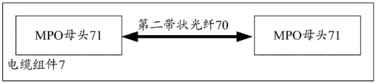
Concrete, described cable assembly comprises the second ribbon fiber and is positioned at many optical patchcords MPO female at described the second ribbon fiber two ends;
Described linkage unit also comprises adapter, and described adapter is for being connected described MPO male with a described MPO female locking.
A kind of switching equipment is also provided, comprises above-specified high density line card, engine, backboard and switching matrix, wherein, described high density line card is connected with described engine, described backboard and described switching matrix respectively.
Concrete, described high-density lines cartoon is crossed gigabit management interface and is connected with described backboard.
Also comprise a kind of group system, comprise at least two above-mentioned switching equipment, between described switching equipment, by cable assembly, connect between two.
Concrete, described cable assembly comprises the second ribbon fiber and is positioned at many optical patchcords MPO female at described the second ribbon fiber two ends.
A kind of electrical signal types collocation method based on high density line card is also provided, is applied to above-specified high density line card, described method comprises:
Described control unit determines that whether described photoelectric conversion unit is in place;
If in place, obtain after the electrical signal types of described photoelectric conversion unit support, notify described signal of telecommunication converting unit, and indicate described signal of telecommunication converting unit in the future the signal of telecommunication of the backboard of self-exchange equipment after converting the electrical signal types of described photoelectric conversion unit support to, send to described photoelectric conversion unit.
The high density line card that the embodiment of the present invention provides, switching equipment, group system and electrical signal types collocation method, in this high density line card, do not re-use MAC chip, but use photoelectric conversion unit, because the power consumption of photoelectric conversion unit is very low, thereby just can greatly reduce the power consumption of whole high density line card; And the linkage unit in this high density line card connects other switching equipment by cable assembly, does not re-use optical module, so just can greatly reduce interconnected cost.
Embodiment
For the structure of existing line card, cause all very high problems of interconnected cost and power consumption, the embodiment of the present invention provides a kind of high density line card, this high density line card is applied in switching equipment, structure comprises control unit 50, signal of telecommunication converting unit 51, photoelectric conversion unit 52 and linkage unit 53 as shown in Figure 5, wherein:
Control unit 50, for obtaining after the electrical signal types of photoelectric conversion unit 52 supports, notice signal of telecommunication converting unit 51.
Signal of telecommunication converting unit 51, after converting for the signal of telecommunication of the backboard of self-exchange equipment in the future the electrical signal types that photoelectric conversion unit 52 supports to, send to photoelectric conversion unit 52, or send to backboard after the signal of telecommunication from 52 yuan of opto-electronic conversion lists being converted to the electrical signal types of backboard support.
Photoelectric conversion unit 52, sends to linkage unit 53 for converting the signal of telecommunication from signal of telecommunication converting unit 51 to light signal, or converts the light signal from linkage unit 53 to the signal of telecommunication and send to signal of telecommunication converting unit 51.
Linkage unit 53, for connecting other switching equipment by cable assembly; Light signal from other switching equipment is sent to photoelectric conversion unit 52, or the light signal from photoelectric conversion unit 52 is sent to other switching equipment.
In this high density line card, do not re-use MAC chip, but use photoelectric conversion unit, because the power consumption of photoelectric conversion unit is very low, thereby just can greatly reduce the power consumption of whole high density line card; And the linkage unit in this high density line card connects other switching equipment by cable assembly, does not re-use optical module, so just can greatly reduce interconnected cost.
Concrete, control unit is connected with signal of telecommunication converting unit by serial management interface (Serial Management Interface, SMI) bus, and control unit is connected with photoelectric conversion unit by I2C bus;
Control unit, specifically for reading by I2C bus after the electrical signal types of photoelectric conversion unit support, the electrical signal types reading in the configuration of signal of telecommunication converting unit by SMI bus.
Control unit, by the electrical signal types of supporting at signal of telecommunication converting unit configuration photoelectric conversion unit, has been realized the signal of telecommunication on backboard and can have been sent to photoelectric conversion unit by signal of telecommunication converting unit, and then sent to other switching equipment.
Concrete, photoelectric conversion unit comprises parallel optical sending device and parallel optical receiving device, wherein:
Parallel optical sending device, for the signal of telecommunication from signal of telecommunication converting unit is converted to after light signal, sends to linkage unit;
Parallel optical receiving device, for the light signal from linkage unit is converted to after the signal of telecommunication, sends to signal of telecommunication converting unit.
Concrete, as shown in Figure 6, linkage unit 53 comprises the first ribbon fiber 530 and many optical patchcords (Multi-fiber Push On, the MPO) male 531 that is positioned at first ribbon fiber one end, wherein: the first ribbon fiber 530 is connected with photoelectric conversion unit 52.
Concrete, as shown in Figure 7, cable assembly 7 comprises the second ribbon fiber 70 and is positioned at the MPO female 71 at the second ribbon fiber two ends;
Linkage unit also comprises adapter, and adapter is for being connected MPO male with a MPO female locking.
By adapter, cable assembly and linkage unit can be linked together securely, guarantee proper communication between the interconnected switching equipment of VSU.
Based on same inventive concept, the embodiment of the present invention also provides a kind of switching equipment, the structure of this switching equipment as shown in Figure 8, comprise high density line card 80, engine 81, backboard 82, switching matrix 83 and line card 84 as shown in Figure 5, wherein, high density line card 80 is connected with engine 81, backboard 82 and switching matrix 83 respectively, and engine 81, switching matrix 83 and line card 84 can be at least one, only illustrates one in Fig. 8.
Concrete, high density line card 80 is connected with backboard 82 by gigabit management interface.
Based on same inventive concept, the embodiment of the present invention also provides a kind of group system, comprises at least two switching equipment as shown in Figure 8, connects between two between switching equipment by cable assembly, can adopt cable assembly as shown in Figure 7.
Two the rack switching equipment of take are below realized 480G bandwidth VSU, and interconnected as example is come, the present invention is described in detail.
Figure 9 shows that the Organization Chart of the switching equipment in the present embodiment, wherein engine, line card and switching matrix are consistent with Fig. 2, have increased a high density line card in Fig. 9, realize switching equipment across the high bandwidth clustered system interconnection between frame.
The structure of high density line card as shown in figure 10, contrast common line card, use " PHY chip+parallel optical device+linkage unit " to substitute original " MAC chip+PHY chip ", the hardware cost of the two is substantially suitable, but the power consumption of high density line card will be far below common line card, and parallel optical device is the device that is similar to optical module, power consumption is much smaller than MAC chip, the power consumption of 1 pair of parallel optical device is less than 4W, and still, the power consumption of a high bandwidth MAC chip reaches 100W conventionally.
Introduce in detail the function of each device in high density line card below, control unit 50 in CPU correspondence and Fig. 5, signal of telecommunication converting unit 51 in PHY chip correspondence and Fig. 5, linkage unit 53 in photoelectric conversion unit 52,24 core high density flat cable assemblies in parallel optical device correspondence and Fig. 5 and front-panel connector correspondence and Fig. 5.
CPU: for receiving the management information of engine, and by SMI, PHY chip is configured, by I2C bus, parallel optical device is managed and configured.Because the type of the signal of telecommunication is very abundant, there is the interconnected interface of backboard defining in KR(802.3, there are two kinds of interfaces of 40GBASE-KR4 and 10GBASE-KR), the 10G defining in SFI(IEEE802.3 standard connects additional (the Physical Medium Attachment of physical medium, PMA) layer (Physical Medium Dependent relevant with physical medium, PMD) layer interface) etc. a variety of, can not every kind of signal of telecommunication can converge to parallel optical device and realize opto-electronic conversion, CPU will obtain the electrical signal protocol that parallel optical device is supported by I2C bus, then by configuration PHY chip, the signal of telecommunication of realizing backboard converts the signal of telecommunication that is applicable to parallel optical device to.
PHY chip: change for electrical signal protocol, because KR4 signal is defined as the signal for backboard transmission in standard, be not suitable for away front panel port, in this example for by the 40GBASE-KR4(802.3ap definition in Institute of Electrical and Electronics Engineers (Institute of Electrical and Electronics Engineers, IEEE) 802.3ap standard for the interconnected interface of 40G signal backplane) signal be converted in the XLPPI(IEEE802.3ba standard of IEEE802.3ba standard, define for 40G, connect the interface of PMA layer and pmd layer) signal.
Parallel optical device: comprise parallel optical sending device and parallel optical receiving device, it is a kind of high channel density module, there is multiple module overall dimension, each module can be supported the ethernet link of the 10.3125Gbps speed of 10 to 12 paths, for example, for the embedded MiniPOD parallel optical of 12 passage device, the highest speed that can support 120Gbps.
24 core high density flat cable assembly and front-panel connectors: for carrying out inserting with parallel optical device, cable assembly has 2 joints that can insert parallel optical device, and the flat type optical fiber by 2 12 cores is connected to MPO male respectively.The flat type optical fiber of 2 12 cores connects respectively parallel optical sending device and parallel optical receiving device, realizes the speed of 120Gbps.The present invention uses the flat type optical fiber of 4 12 cores to coordinate 4 pairs of embedded parallel optical devices, totally realizes the transmission rate of 480Gbps; Front-panel connector has 4 adapters, and the size of whole connector only has the size of 3 40G optical modules, but can realize the bandwidth of 480G.
Between two switching equipment, realize the interconnected structure of VSU as shown in figure 11, front-panel connector is by the MPO female in 24 core high-density cable assemblies and the locking of the MPO male in front-panel connector, by 4 24 core high-density cable assemblies, the VSU that just can realize 480G bandwidth between 2 switching equipment is interconnected.
In this application scenarios, the power consumption of high density line card is less than 1/3 of line card in prior art; As long as 4 24 core ribbon fibers can be realized the interconnected of 480G bandwidth, than prior art, need 12 copper to look at or optical fiber cable, the present invention has reduced wiring difficulty; Without using optical module, greatly reduce interconnected cost; Interconnected transmission be light signal, transmission range can reach 100m, much larger than copper, lookes at, and substantially meets the interconnected demand of VSU; Without using optical module, bandwidth can not be subject to the restriction of optical module physical size, and equipment room interconnected is to use MPO male and female head to match interconnected realization, realizes 480G bandwidth, and size is less than 1/4 of 12 40G ports.
Based on same inventive concept, the embodiment of the present invention also provides a kind of electrical signal types collocation method based on high density line card, and as shown in figure 12, executive agent is control unit to the flow process of the method, and step is as follows:
S120: after high density line card has powered on, carry out initialization.
S121: determine that whether photoelectric conversion unit is in place, if in place, carry out S122; Otherwise, continue to carry out S121.
S122: obtain after the electrical signal types of photoelectric conversion unit support, notice signal of telecommunication converting unit, and indicate signal of telecommunication converting unit in the future the signal of telecommunication of the backboard of self-exchange equipment after converting the electrical signal types of photoelectric conversion unit support to, send to photoelectric conversion unit.
The present invention is with reference to describing according to flow chart and/or the block diagram of the method for the embodiment of the present invention, equipment (system) and computer program.Should understand can be in computer program instructions realization flow figure and/or block diagram each flow process and/or the flow process in square frame and flow chart and/or block diagram and/or the combination of square frame.Can provide these computer program instructions to the processor of all-purpose computer, special-purpose computer, Embedded Processor or other programmable data processing device to produce a machine, the instruction of carrying out by the processor of computer or other programmable data processing device is produced for realizing the device in the function of flow process of flow chart or a plurality of flow process and/or square frame of block diagram or a plurality of square frame appointments.
These computer program instructions also can be stored in energy vectoring computer or the computer-readable memory of other programmable data processing device with ad hoc fashion work, the instruction that makes to be stored in this computer-readable memory produces the manufacture that comprises command device, and this command device is realized the function of appointment in flow process of flow chart or a plurality of flow process and/or square frame of block diagram or a plurality of square frame.
These computer program instructions also can be loaded in computer or other programmable data processing device, make to carry out sequence of operations step to produce computer implemented processing on computer or other programmable devices, thereby the instruction of carrying out is provided for realizing the step of the function of appointment in flow process of flow chart or a plurality of flow process and/or square frame of block diagram or a plurality of square frame on computer or other programmable devices.
Although described optional embodiment of the present invention, once those skilled in the art obtain the basic creative concept of cicada, can make other change and modification to these embodiment.So claims are intended to be interpreted as all changes and the modification that comprise optional embodiment and fall into the scope of the invention.
Obviously, those skilled in the art can carry out various changes and modification and not depart from the spirit and scope of the embodiment of the present invention the embodiment of the present invention.Like this, if within these of the embodiment of the present invention are revised and modification belongs to the scope of the claims in the present invention and equivalent technologies thereof, the present invention is also intended to comprise these changes and modification interior.