CN103575021A - Aquatic product freezer - Google Patents
Aquatic product freezer Download PDFInfo
- Publication number
- CN103575021A CN103575021A CN201310544182.4A CN201310544182A CN103575021A CN 103575021 A CN103575021 A CN 103575021A CN 201310544182 A CN201310544182 A CN 201310544182A CN 103575021 A CN103575021 A CN 103575021A
- Authority
- CN
- China
- Prior art keywords
- water inlet
- ice
- ice sheet
- inlet pipe
- passage
- Prior art date
- Legal status (The legal status is an assumption and is not a legal conclusion. Google has not performed a legal analysis and makes no representation as to the accuracy of the status listed.)
- Granted
Links
Images


Abstract
The invention relates to aquatic product processing equipment. An aquatic product freezer comprises a rapid freezing room and a conveying belt penetrating through the rapid freezing room, wherein the conveying belt is provided with a plurality of rapid freezing box supporting frames distributed along the extending direction of the conveying belt; the rapid freezing box supporting frames comprise upper substrates, middle substrates and lower substrates arranged sequentially; a plurality of upper inclined supporting plates are arranged between the upper substrates and the middle substrates; upper deformation channels extending along the horizontal direction are formed among the upper substrates, the middle substrates and the upper inclined supporting plates; a plurality of lower inclined supporting plates are arranged between the lower substrates and the middle substrates; lower deformation channels are formed among the lower substrates, the middle substrates and the lower inclined supporting plates; the lower substrates are connected with the conveying belt. According to the aquatic product freezer provided by the invention, the vibration of the rapid freezing box generated in the conveying process is little, so that the problem of overflow of water in the rapid freezing box caused by the vibration generated in the conveying process of the existing rapid freezers is solved.
Description
Technical field
The present invention relates to aquatic products processing equipment, relate in particular to a kind of aquatic products freezer, belong to aquatic products processing field.
Background technology
In order to prevent that aquatic products from rotting in storage process in transportation, transport storage after need to aquatic products is freezing.Aquatic products is carried out freezingly by instant freezer, completing.In China Patent No., be 932240216, Granted publication day be Mays 25 nineteen ninety-five day, be called in the patent document of " tunnel type single-freezing machine " and disclose a kind of freezer, the quick-freezing plant in this patent document comprises by moist closet and is positioned at quick-frozen chamber that the quick-frozen mechanism of moist closet forms, is positioned at the indoor conveyer belt of quick-frozen.During use, the fast freezing case that thing to be frozen and water are housed is placed on conveyer belt, conveyer belt makes fast freezing case pass quick-frozen chamber, and fast freezing case water when the quick-frozen chamber is frozen into ice and is wrapped on thing to be frozen and forms and freeze product.Existing tunnel type quick-frozen machine is generally inserted in following deficiency: conveyer belt does not have shock insulation function, and the vibration producing in course of conveying can make the water in fast freezing case shake out; When aquatic products are carried out to full packaging type quick-frozen, ice cube is solid state, after therefore freezing freeze product Heavy Weight, cost of transportation is high to freeze product Heavy Weight.
Summary of the invention
The first object of the present invention aims to provide the little aquatic products freezer of vibration that in a kind of process of carrying fast freezing case, fast freezing case produces, and has solved the problem that the vibration that produces in existing instant freezer course of conveying can make the water in fast freezing case shake out.
Second object of the present invention is intended to further provide the aquatic products freezer that a kind of ice cube that can make to be wrapped in outside article is pore space structure, and having solved the formed ice cube wrapping in outside article of existing instant freezer is the problem of freezing product Heavy Weight that solid construction causes.
Above technical problem solves by following technical proposal: a kind of aquatic products freezer, comprise quick-frozen chamber and through the conveyer belt of quick-frozen chamber, described conveyer belt is provided with some fast freezing case bracing frames that distribute along conveyer belt bearing of trend, described fast freezing case bracing frame comprises the upper substrate distributing successively, middle substrate and infrabasal plate, between upper substrate and middle substrate, be provided with some upper bearing diagonal plates, upper substrate, between middle substrate and upper bearing diagonal plate, surround the upper deformation passage that along continuous straight runs extends, between infrabasal plate and middle substrate, be provided with some declivity gripper shoes, infrabasal plate, between middle substrate and declivity gripper shoe, surround lower deformation passage, described infrabasal plate and described conveyer belt link together.During use, fast freezing case is shelved on and on base portion, is transferred band and is transported to that quick-frozen is indoor carries out quick-frozen.When conveyer belt produces vibration, fast freezing case bracing frame can play vibration isolation effect, and the vibration that conveyer belt is produced is difficult for passing in fast freezing case, and the little water being contained in fast freezing case of vibration that fast freezing case is subject to is difficult for being shaken out.The above version of fast freezing case bracing frame can guarantee with platy structure the intensity of structural strength, integrally bending and torsion, weight reduction simultaneously.Therefore the fast freezing case bracing frame of this structure both had advantages of plank frame compactness, take up room little, outward appearance is succinct, has advantages of that again the vibration isolating effect of truss structure is good.
As preferably, described upper bearing diagonal plate and declivity gripper shoe are all corrugated plating, the bearing of trend of the groove of the ripple on described upper bearing diagonal plate is identical with the bearing of trend of upper distortion passage, and the bearing of trend of the groove of the ripple in described declivity gripper shoe is identical with the bearing of trend of lower distortion passage.Can improve the energy-absorbing damping effect of fast freezing case bracing frame.
As preferably, the bearing of trend of described lower distortion passage is identical with the bearing of trend of upper distortion passage, the two ends of described upper deformation passage and lower deformation passage are provided with end cap, in described upper bearing diagonal plate, described, are all provided with damp channel in upper bearing diagonal plate between deformation passage, described declivity gripper shoe on adjacent in the declivity gripper shoe between described adjacent lower deformation passage and middle substrate on adjacent upper deformation passage and the position between lower deformation passage.During use, in distortion passage, pack damping fluid into.Fast freezing case bracing frame is subject to vibratory impulse and produces when distortion and can impel damping fluid back and forth to flow between different deformation passages through damp channel, and damping fluid and damp channel produce friction and change vibrational energy into heat energy, thereby play vibration isolation effect.
As preferably, in described upper distortion passage and lower distortion passage, be provided with energy-absorbing bar, the bearing of trend of described energy-absorbing bar is identical with the bearing of trend of described upper deformation passage.When fast freezing case bracing frame is subject to high frequency and vibrates by a narrow margin, deformation passage can not produce distortion or deformation minimum, now damping fluid can not flow in damp channel, therefore high frequency vibrates by a narrow margin, is not easy to be eliminated.Thereby now energy-absorbing bar can produce rock and with liquid produce friction to high frequency by a narrow margin vibrational energy effectively eliminate.Can further improve the energy-absorbing vibration isolating effect of fast freezing case bracing frame.
As preferably, in described fast refrigerating chamber, be provided with the ice hole forming He Bing of mechanism hole capping mechanism, described ice hole forming mechanism comprises some ice hole sizing post and ice hole sizing post liftable is connected to the first indoor elevating mechanism of described quick-frozen, described ice hole capping mechanism comprises some ice sheet formed pipes, cover the pipe of the removing lid in ice sheet formed pipe lower end, with the ice sheet knock pin of ice sheet formed pipe alignment and the second elevating mechanism of driving knock pin lifting, described ice sheet formed pipe is provided with into water port, the lower end of described ice sheet formed pipe is provided with ice sheet profiled section, described ice hole forming mechanism and described ice hole capping mechanism are positioned at the top of described conveyer belt, described ice hole forming mechanism and described ice hole capping mechanism distribute from back to front successively along the throughput direction of described conveyer belt, the described ice hole sizing quantity of post and the quantity of described ice sheet formed pipe equate, the described ice hole formed array of sizing post is identical with the formed array of described ice sheet formed pipe.Thereby the formation that can make to be included in the ,Bing hole, ice hole that forms enclosed construction in the ice outside article is played the weight reducing of ice reduces the effect of freezing product weight.And ice hole is enclosed construction, can reduce the ice that freezes in product with the contact area of air, the little ice freezing in product of contact area is not easy to melt.Can not realize the reduction freeze product weight in the situation that substantially do not reduce the thawing time of freezing product.The meaning of " the formed array of described ice hole sizing post is with identical with the formed array of described ice sheet formed pipe " refers to that ice sheet formed pipe can align correspondingly with ice hole when being provided with the freezing product and be positioned at below ice hole capping mechanism of ice hole.Convenient during capping ice hole.Realized second goal of the invention of the present invention.
As preferably, described ice sheet profiled section is provided with electrothermal tube, and described electrothermal tube is along described ice sheet, to form the loop configuration of the circumferential extension of section.When ejecting ice sheet, by electrothermal tube, heat, ice sheet is departed from ice sheet formed pipe.In the time of can making to release ice sheet, facilitate and can not produce the phenomenon of ice sheet fragmentation, ice sheet is not broken can guarantee that ice hole is covered; Can make again to there is enough water on ice sheet side face, guarantee that ice sheet can be frozen on ice hole.The loop configuration that electrothermal tube is set to form the circumferential extension of section along described ice sheet can make rapidly to produce between ice sheet and ice sheet formed pipe loosening and water and produce on the side face of ice sheet.
As preferably, described ice hole sizing post comprises path section and the large footpath section that starts to set gradually from free end, and the aperture area of described ice sheet profiled section is greater than the cross-sectional area of described path section and is less than the cross-sectional area of described large footpath section.Can make ice sheet cover in the outer end in ice hole and not drop to the bottom in ice hole, making the position of ice sheet in ice hole controlled.Convenient while extracting ice hole forming post out.Certainly by ice hole forming column production, be that taper is also passable.But when ice sheet is placed in ice hole during taper, may produce rollover phenomenon, the reliability that ice sheet is covered to ice pore chamber does not have the good of the technical program.
As preferably, described ice sheet formed pipe is also provided with sealed tube and water inlet pipe, the end face at the axial two ends of described sealed tube is all provided with the annular slot circumferentially extending along sealed tube, on the interior lateral wall of described slot, be respectively provided with some annular seal lips that circumferentially extend along sealed tube, described sealing lip is along the axial distribution of sealed tube, the end face of described water inlet pipe is provided with the annular water inlet pipe portion tongue circumferentially extending along water inlet pipe, described water inlet port is provided with the annular water inlet end oral area tongue circumferentially extending along water inlet port, described water inlet pipe portion's tongue and water inlet end oral area tongue are inserted in respectively and are arranged in the described slot at the axial two ends of described sealed tube and are sealed connected together with described sealing lip.Existing sealing between water inlet pipe and water inlet port is to realize sealing by water inlet pipe and water inlet port crush seal packing ring, can produce the phenomenon of poor sealing when producing loosening or twisting between water inlet pipe and water inlet port.Sealing effectiveness in the technical program is not subject to the impact of the connection power between water inlet pipe and water inlet port, can realize the positiver sealing between water inlet pipe and water inlet port.
As preferably, described sealing lip comprises the introversion sealing lip that flare sealing lip that free end tilts towards described slot openend and free end tilt towards described slot diapire, and introversion sealing lip is between flare sealing lip and slot diapire.Sealing force when water inlet pipe and water inlet port produce separating force, between sealing lip and tongue can become greatly thereupon, and when hydraulic pressure improves, sealing lip also can become greatly with the sealing force between tongue equally, good sealing effect.
As preferably, described water inlet pipe outer surface is provided with the annular water inlet pipe portion distending groove being deep in described water inlet pipe portion tongue, in described water inlet pipe portion distending groove, be plugged with water inlet pipe portion sealing and reinforcing ring, the outer surface of described water inlet port is provided with the annular water end (W.E.) oral area portion distending groove being deep in described water inlet end oral area tongue, in described water end (W.E.) oral area portion distending groove, is plugged with water end (W.E.) oral area portion sealing and reinforcing ring.Convenient while regulating the sealing force between sealing lip and tongue.
As preferably, described water inlet port end face is provided with storage tank, and described water inlet end oral area tongue is positioned at the diapire of described storage tank, and described sealed tube is built in described storage tank.The sealing that can prevent from damaging or affecting in the process of water inlet pipe and water inlet port assemblies sealed tube, security reliability is good.
The present invention has following advantage: by the fast freezing case bracing frame with shock-absorbing function is set on conveyer belt, make the vibration on conveyer belt be difficult for being delivered in the fast freezing case being shelved on fast freezing case bracing frame, thereby can effectively avoid the water in fast freezing case in course of conveying to shake out; In preferred version, treat and freeze article and carry out the ice of the formation on ice hole that packaging type can be in freezing product when freezing, thereby can reduce the weight of freezing product, the reduction of freezing product weight can be played the effect that reduces cost of transportation.
Accompanying drawing explanation
Fig. 1 is the structural representation of the embodiment of the present invention one.
Fig. 2 is the local enlarged diagram at the A place of Fig. 1.
Fig. 3 is the local enlarged diagram at the B place of Fig. 2.
Fig. 4 is the structural representation of the fast freezing case bracing frame in the embodiment of the present invention two.
Fig. 5 is the local enlarged diagram at the C place of Fig. 4.
Fig. 6 is the structural representation of the embodiment of the present invention three.
Fig. 7 is the local enlarged diagram at the D place of Fig. 6.
Fig. 8 is the use view of the embodiment of the present invention three.
Fig. 9 is the schematic diagram of the junction of the water inlet pipe in embodiment tetra-and the port of intaking.
Figure 10 is the local enlarged diagram at the E place of Fig. 9.
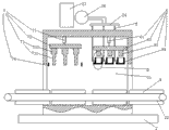
In figure: water inlet port one, storage tank 11, water inlet end oral area tongue 12, water inlet end oral area distending groove 13, water inlet end oral area sealing and reinforcing ring 14, frame 2, quick-frozen chamber 21, feeding gate 211, discharge door 212, conveyer belt 22, water tank 23, tube sheet 24, water pump 25, freeze product 3, article 31 to be frozen, water 32, ice 33, ice hole 34, ice sheet 35, fast freezing case 4, water inlet pipe 5, water inlet pipe portion tongue 51, water inlet pipe portion distending groove 52, water inlet pipe portion sealing and reinforcing ring 53, attaching nut 54, ice hole capping mechanism 6, the second elevating mechanism 61, the second upper frame 62, ice sheet knock pin 63, ice sheet formed pipe 64, ice sheet profiled section 641, electrothermal tube 642, pipe covers 66, hinge 661, the motor 662 of uncapping, ice hole forming mechanism 7, the first elevating mechanism 71, the first upper frame 72, ice hole sizing post 73, path section 731, large footpath section 732, freeze product resistance and rise frame 74, fast freezing case bracing frame 8, upper substrate 81, middle substrate 82, infrabasal plate 83, upper bearing diagonal plate 84, the groove 841 of the ripple on upper bearing diagonal plate, upper deformation passage 85, declivity gripper shoe 86, the groove 861 of the ripple in declivity gripper shoe, lower distortion passage 87, damp channel 88, energy-absorbing bar 89, rolling groove 891, end cap 80, sealed tube 9, slot 91, slot diapire 911, sealing lip 92, flare sealing lip 921, introversion sealing lip 922.
The specific embodiment
Below in conjunction with accompanying drawing and embodiment, the present invention is further illustrated.
Embodiment mono-, and referring to Fig. 1, a kind of aquatic products freezer, comprises frame 2.In frame 2, be provided with quick-frozen chamber 21 and conveyer belt 22.Quick-frozen chamber 21 is existing structure.Quick-frozen chamber 21 is provided with feeding gate 211 and discharge door 212.Conveyer belt 22 passes quick-frozen chamber 21 through feeding gate 211 and discharge door 212.Conveyer belt 22 is provided with in some fast freezing case bracing frame 8(the present embodiment that distribute along conveyer belt bearing of trend and has schematically drawn 8).
Referring to Fig. 2, fast freezing case bracing frame 8 comprises upper substrate 81, middle substrate 82 and the infrabasal plate 83 distributing along the vertical direction.Between upper substrate 81 and middle substrate 82, be provided with some upper bearing diagonal plates 84.Between upper substrate 81, middle substrate 82 and upper bearing diagonal plate 84, surround the upper deformation passage 85 that some along continuous straight runs extend.Upper deformation passage 85 is triangle.Between infrabasal plate 83 and middle substrate 82, be provided with some declivity gripper shoes 86.Between infrabasal plate 83, middle substrate 82 and declivity gripper shoe 86, surround the lower deformation passage 87 that some along continuous straight runs extend.Lower deformation passage 87 is triangle.The bearing of trend of lower distortion passage 87 is identical with the bearing of trend of upper distortion passage 85.Infrabasal plate 83 and conveyer belt 22 link together.
Referring to Fig. 3, upper bearing diagonal plate 84 and declivity gripper shoe 86 are all corrugated plating.The bearing of trend of the groove 861 of the bearing of trend of the groove 841 of the ripple on upper bearing diagonal plate and ripple in declivity gripper shoe is identical.
Referring to Fig. 1, to Fig. 3, during use, fast freezing case is shelved on upper substrate 81 and is transferred with 22 and is transported in quick-frozen chamber 21 article in fast freezing case are carried out to quick-frozen.
Embodiment bis-, referring to Fig. 4, with the difference of embodiment bis-, are: the two ends of upper deformation passage 85 and lower deformation passage 87 are provided with end cap 80, make deformation passage 85 and lower deformation passage 87 all form the cavity sealing.In upper bearing diagonal plate 84 on adjacent in the upper and lower bearing diagonal plate 86 of upper bearing diagonal plate between deformation passage 85 in the declivity gripper shoe between adjacent lower deformation passage 87 and middle substrate 82 on adjacent upper deformation passage and the position between lower deformation passage, be all provided with damp channel 88.In upper deformation passage 85 and lower deformation passage 87, be all filled with damping fluid (damping fluid does not draw in the drawings).In upper deformation passage 85 and lower deformation passage 87, be provided with the energy-absorbing bar 89 being suspended in damping fluid.The bearing of trend of energy-absorbing bar 89 is identical with the bearing of trend of upper deformation passage 85.
Referring to Fig. 5, the surface of energy-absorbing bar 89 is provided with the rolling groove 891 extending along the bearing of trend of energy-absorbing bar 89.When the damping fluid in upper distortion passage 85, lower distortion passage 87 produces vibration, rolling groove 891 can accelerate rocking of energy-absorbing bar 89, plays the effect that improves energy-absorbing effect.
Referring to Fig. 4, when fast freezing case bracing frame 8 is subject to vibrating, can produce deformation and cause deformation passage 85 and lower deformation passage 87 to produce distortion, during distortion, damping fluid moves back and forth between each deformation passage through damp channel 88, produces friction and energy-absorbing when damping fluid is flowed through damp channel 88.When the vibration being subject to is high frequency while vibrating by a narrow margin, deformation is not enough to impel damping fluid to flow between deformation passage, but now energy-absorbing bar 89 still can produce and rock, and when energy-absorbing bar 89 rocks, with damping fluid, produces and rubs and energy-absorbing.
Embodiment tri-, with the difference of embodiment bis-, are:
Referring to Fig. 6, the outside of quick-frozen chamber 21 is provided with water tank 23, tube sheet 24 and water pump 25.Water pump 25 is constant displacement pump.The import of water pump 25 links together with water tank 23.The outlet of water pump 25 and tube sheet 24 are docking together.
In quick-frozen chamber 21, be provided with 7 He Bing hole capping mechanisms 6 of ice hole forming mechanism.
Ice hole forming mechanism 7 is positioned at the top of conveyer belt 22.Ice hole forming mechanism 7 comprises the first elevating mechanism 71, the first upper frame 72, ice hole sizing post 73 and freezes product resistance and rises frame 74.The first elevating mechanism 71 is cylinder.The first elevating mechanism 71 is suspended on the first upper frame 72 roof of quick-frozen chamber 21.The upper end of ice hole sizing post 73 links together with the first upper frame 72.The lower end of ice hole sizing post 73 is free end.Ice hole sizing post 73 comprises from bottom to top path section 731 and large footpath section 732 successively.Path section 731 and large footpath section 732 are all column type.Ice hole sizing post 73 has 12 (in figure, can only see three).Freeze product resistance and rise frame 74 between the first upper frame 72 and conveyer belt 22.
Ice hole capping mechanism 6 is positioned at the right side of ice hole forming mechanism 7.Ice hole capping mechanism 6 is positioned at the top of conveyer belt 22.Ice hole capping mechanism 6 comprises the second elevating mechanism 61, the second upper frame 62, ice sheet knock pin 63 and ice sheet formed pipe 64.The second elevating mechanism 61 is cylinder.The second elevating mechanism 61 is suspended on the second upper frame 62 roof of quick-frozen chamber 21.The upper end of ice sheet knock pin 63 is fixed together with the second upper frame 62.Ice sheet knock pin 63 has 12 (in figure, can only see 3).Ice sheet formed pipe 64 is fixed together with quick-frozen chamber 21.Ice sheet formed pipe 64 has 12.12 ice sheet formed pipes 64 be positioned at correspondingly 12 ice sheet knock pins 63 under.The cross-sectional area that the aperture area of ice sheet formed pipe 64 is greater than ice sheet knock pin 63 is that ice sheet knock pin 63 can be inserted in ice sheet formed pipe 64.The ice hole formed array of sizing post 73 is with identical with the formed array of ice sheet formed pipe 64.Ice sheet formed pipe 64 is for prolonging axially the equal pipe of internal diameter everywhere in edge.The aperture area of ice sheet formed pipe 64 is greater than the cross-sectional area of path section 731.The aperture area of ice sheet formed pipe 64 is less than the cross-sectional area of large footpath section 732.Ice sheet formed pipe 64 is provided with water inlet pipe 5.Water inlet pipe 5 is heat-insulated pipe.The upper end of water inlet pipe 5 and tube sheet 24 are docking together.
Referring to Fig. 7, ice sheet formed pipe 64 lower ends form ice sheet profiled section 641.Ice sheet formed pipe 64 is provided with into water port one.The lower end of water inlet port one and water inlet pipe 5 is sealed connected together.Water inlet port one is positioned at the top of ice sheet profiled section 641.Ice sheet profiled section 641 places are provided with electrothermal tube 642.Electrothermal tube 642 is along ice sheet, to form the loop configuration of the circumferential extension of section 641.Ice sheet formed pipe 64 lower ends are stamped pipe and are covered 66.Pipe cover 66, and to pass through hinge 661 hinged with ice sheet formed pipe 64.Hinge 661 links together with the power output shaft of the motor 662 of uncapping.
Referring to Fig. 8 and in conjunction with Fig. 7, during use, at the in-built water of water tank 23.The fast freezing case 4 that article 31 to be frozen and water 32 are housed is placed on and in fast freezing case bracing frame 8, is positioned at conveyer belt 22 left ends and is positioned on the fast freezing case bracing frame of 21 outsides, quick-frozen chamber.Conveyer belt 22 travels from left to right and fast freezing case 4 is transported in quick-frozen chamber 21, and when fast freezing case 4 is just positioned at the below of ice hole forming mechanism 7, conveyer belt 22 stops.The first elevating mechanism 71 drives the first upper frames 72 to decline, and the first upper frame 72 drives ice hole forming posts 73 to drop to large footpath section 732 and is inserted in the water freezing in product storage bin unnecessary water is flowed out.Under the effect of quick-frozen chamber 21, the water 32 in fast freezing case 4 is formed the ice 33 being wrapped on article 31 to be frozen.Article 31 to be frozen and ice 33 formations are frozen product 3.The first elevating mechanism 71 rises ice hole forming post 73 and extracts in ice 33, as jelly product 3 rise together in company with ice hole forming post 73, freeze product resistance and rise the rising that frame 74 obstructions are frozen product 3, ice hole forming post 73 can be extracted, in ice 33, form step-like ice hole 34.Pipe covers 66 lower ends of covering at ice sheet formed pipe 64.Water pump 25 by the water of set amount from water tank 23 in water inlet pipe 5 is transported to each root ice sheet formed pipe 64, under the effect of quick-frozen chamber 21, be arranged in the water freezing of ice sheet formed pipe 64 and form ice sheet 35.Conveyer belt 22 moves ahead, and to be right lateral stop after the fast freezing case 4 that freezes product 3 is housed is positioned at the below of ice hole capping mechanism 6.Effect lower tube cap 66 at the motor 662 of uncapping rotates and staggers with the lower end of ice sheet formed pipe 64.Heating tube 643 heating ice sheets 35 make ice sheet 35 side faces produce thawing, the second lift cylinder 61 drives ice sheet knock pin 63 to decline by the second upper frame 62, ice sheet knock pin 63 corresponding the is inserted in ice sheet formed pipe 64 and ice sheet 35 is ejected one by one, and ice sheet 35 drops to correspondingly in ice hole 34 and is shelved on the step in ice hole 34.Under the effect of quick-frozen chamber 21, the lip-deep water cure of ice sheet 35 and by ice sheet 35 and ice 33 in conjunction with in together with.Then conveyer belt 22 by be equipped with freeze product 3 fast freezing case 4 from discharge door 212 outputs.
Embodiment tetra-, referring to Fig. 9, with the difference of embodiment tri-, are: water inlet port one end face is provided with annular storage tank 11.Storage tank 11 diapires are provided with water inlet end oral area tongue 12.Water inlet port one surface is provided with the annular water inlet end oral area distending groove 13 extending in water inlet end oral area tongue 12.The section of water inlet end oral area distending groove 13 is narrow trapezoidal in the wide bottom of openend.In water inlet end oral area distending groove 13, be plugged with water inlet end oral area sealing and reinforcing ring 14.The section of water inlet end oral area sealing and reinforcing ring 14 is wide trapezoidal in inner (i.e. left end in figure) narrow outer end.Storage tank 11, water inlet end oral area tongue 12, water inlet end oral area distending groove 13 and water inlet end oral area sealing and reinforcing ring 14 4 all circumferentially extend along water inlet port one.
In storage tank 11, be provided with sealed tube 9.Sealed tube 9 is parallel with the axis of storage tank 11.Water inlet pipe 5 is provided with annular water inlet pipe portion tongue 51.Water inlet pipe 5 surfaces are provided with the annular water inlet pipe portion distending groove 52 extending in water inlet pipe portion tongue.The section of water inlet pipe portion distending groove 52 is narrow trapezoidal in the wide bottom of openend.In water inlet pipe portion distending groove 52, be plugged with water inlet pipe portion sealing and reinforcing ring 53.The section of water inlet pipe portion sealing and reinforcing ring 53 is wide trapezoidal in inner (i.e. right-hand member in figure) narrow outer end.Water inlet pipe portion tongue 51, water inlet pipe portion distending groove 52 and sealing and reinforcing ring 53 threes of water inlet pipe portion circumferentially extend along water inlet pipe 5.
Referring to Figure 10, the end face at the axial two ends of sealed tube 9 in figure left and right end face be all provided with annular slot 91.Slot 91 circumferentially extends along sealed tube 9.On the interior lateral wall of slot 91, be respectively provided with four annular seal lips 92.Sealing lip 92 circumferentially extends along sealed tube 9.Sealing lip 92 on the same sidewall of slot is along sealed tube 9 axial distribution.Four sealing lips 92 on the same sidewall of slot comprise that two free ends are towards flare sealing lip 921 and 2 introversion sealing lips 922 that free end tilts towards slot diapire of the openend inclination of slot.Introversion sealing lip 922 is between flare sealing lip 921 and slot diapire 911.
Referring to Fig. 9 and Figure 10, the method that intake port and water inlet pipe are linked together is: sealed tube 9 is inserted in storage tank 11 and makes water inlet end oral area tongue 12 be inserted in the slot that is positioned at below in two slots 91, the sealing lip in this slot is connected in the inner and outer circumferential surfaces of water inlet end oral area tongue 12.Make water inlet pipe portion tongue 51 be inserted in the slot that is positioned at top in two slots 91, the sealing lip in this slot is connected in the inner and outer circumferential surfaces of water inlet pipe portion tongue 51.Attaching nut 54 is set on water inlet pipe 5, then attaching nut's 54 thread bush are located on water port one, the step on attaching nut 54 is together with step on water inlet pipe 5 is connected to and water inlet pipe and water inlet port are fixed together.Thereby water inlet pipe portion sealing and reinforcing ring 53 is inserted into, water inlet pipe portion distending groove 52 is interior broadens water inlet pipe portion tongue 51 radial thickness to make corresponding sealing lip sealing to be connected on water inlet pipe portion tongue 51.Thereby water inlet end oral area sealing and reinforcing ring 14 is inserted into, water inlet end oral area distending groove 13 is interior broadens water inlet end oral area tongue 12 radial thickness to make corresponding sealing lip sealing to be connected on water inlet end oral area tongue 12.Section due to sealing and reinforcing ring and distending groove in this embodiment is trapezoidal, and the degree of depth that can be inserted into distending groove by further increase sealing and reinforcing ring when causing poor sealing due to reasons such as tired surface agings realizes sealing again.Sealing mode is low to making required precision, easily laborsaving during assembling.Sealing mode can make sealing effectiveness improve rather than become bad as existing sealing means when what kind of relative motion no matter water inlet port one and water inlet pipe 5 produce.If if water penetration of this part water when permeating between sealed tube 9 and storage tank 11 can make tongue and all sealing lip butts obtain tightlier seal better water when permeating between tongue and sealing lip, first water will pass through flare sealing lip, the penetration of this part water can make flare sealing lip and tongue butt obtain tightlier to seal better and water can not be flowed out, thus sealing mode can be along with the rising of hydraulic pressure sealing effectiveness better.
Claims (10)
1. an aquatic products freezer, comprise quick-frozen chamber and through the conveyer belt of quick-frozen chamber, it is characterized in that, described conveyer belt is provided with some household freezer bracing frames that distribute along conveyer belt bearing of trend, described household freezer bracing frame comprises the upper substrate distributing successively, middle substrate and infrabasal plate, between upper substrate and middle substrate, be provided with some upper bearing diagonal plates, upper substrate, between middle substrate and upper bearing diagonal plate, surround the upper deformation passage that along continuous straight runs extends, between infrabasal plate and middle substrate, be provided with some declivity gripper shoes, infrabasal plate, between middle substrate and declivity gripper shoe, surround lower deformation passage, described infrabasal plate and described conveyer belt link together.
2. aquatic products freezer according to claim 1, it is characterized in that, described upper bearing diagonal plate and declivity gripper shoe are all corrugated plating, the bearing of trend of the groove of the ripple on described upper bearing diagonal plate is identical with the bearing of trend of upper distortion passage, and the bearing of trend of the groove of the ripple in described declivity gripper shoe is identical with the bearing of trend of lower distortion passage.
3. aquatic products freezer according to claim 2, it is characterized in that, the bearing of trend of described lower distortion passage is identical with the bearing of trend of upper distortion passage, the two ends of described upper deformation passage and lower deformation passage are provided with end cap, in described upper bearing diagonal plate, described, are all provided with damp channel in upper bearing diagonal plate between deformation passage, described declivity gripper shoe on adjacent in the declivity gripper shoe between described adjacent lower deformation passage and middle substrate on adjacent upper deformation passage and the position between lower deformation passage.
4. aquatic products freezer according to claim 3, is characterized in that, in described upper distortion passage and lower distortion passage, is provided with energy-absorbing bar, and the bearing of trend of described energy-absorbing bar is identical with the bearing of trend of described upper deformation passage.
5. according to the aquatic products freezer described in claim 1 or 2 or 3 or 4, it is characterized in that, in described fast refrigerating chamber, be provided with the ice hole forming He Bing of mechanism hole capping mechanism, described ice hole forming mechanism comprises some ice hole sizing post and ice hole sizing post liftable is connected to the first indoor elevating mechanism of described quick-frozen, described ice hole capping mechanism comprises some ice sheet formed pipes, cover the pipe of the removing lid in ice sheet formed pipe lower end, with the ice sheet knock pin of ice sheet formed pipe alignment and the second elevating mechanism of driving knock pin lifting, described ice sheet formed pipe is provided with into water port, the lower end of described ice sheet formed pipe is provided with ice sheet profiled section, described ice hole forming mechanism and described ice hole capping mechanism are positioned at the top of described conveyer belt, described ice hole forming mechanism and described ice hole capping mechanism distribute from back to front successively along the throughput direction of described conveyer belt, the described ice hole sizing quantity of post and the quantity of described ice sheet formed pipe equate, the described ice hole formed array of sizing post is identical with the formed array of described ice sheet formed pipe.
6. aquatic products freezer according to claim 5, is characterized in that, described ice sheet profiled section is provided with electrothermal tube, and described electrothermal tube is along described ice sheet, to form the loop configuration of the circumferential extension of section.
7. aquatic products freezer according to claim 5, it is characterized in that, described ice hole sizing post comprises path section and the large footpath section that starts to set gradually from free end, and the aperture area of described ice sheet profiled section is greater than the cross-sectional area of described path section and is less than the cross-sectional area of described large footpath section.
8. aquatic products freezer according to claim 5, it is characterized in that, described ice sheet formed pipe is also provided with sealed tube and water inlet pipe, the end face at the axial two ends of described sealed tube is all provided with the annular slot circumferentially extending along sealed tube, on the interior lateral wall of described slot, be respectively provided with some annular seal lips that circumferentially extend along sealed tube, described sealing lip is along the axial distribution of sealed tube, the end face of described water inlet pipe is provided with the annular water inlet pipe portion tongue circumferentially extending along water inlet pipe, described water inlet port is provided with the annular water inlet end oral area tongue circumferentially extending along water inlet port, described water inlet pipe portion's tongue and water inlet end oral area tongue are inserted in respectively and are arranged in the described slot at the axial two ends of described sealed tube and are sealed connected together with described sealing lip.
9. aquatic products freezer according to claim 8, it is characterized in that, described sealing lip comprises the introversion sealing lip that flare sealing lip that free end tilts towards described slot openend and free end tilt towards described slot diapire, and introversion sealing lip is between flare sealing lip and slot diapire.
10. aquatic products freezer according to claim 8, it is characterized in that, described water inlet pipe outer surface is provided with the annular water inlet pipe portion distending groove being deep in described water inlet pipe portion tongue, in described water inlet pipe portion distending groove, be plugged with water inlet pipe portion sealing and reinforcing ring, the outer surface of described water inlet port is provided with the annular water end (W.E.) oral area portion distending groove being deep in described water inlet end oral area tongue, in described water end (W.E.) oral area portion distending groove, is plugged with water end (W.E.) oral area portion sealing and reinforcing ring.
Priority Applications (1)
| Application Number | Priority Date | Filing Date | Title |
|---|---|---|---|
| CN201310544182.4A CN103575021B (en) | 2013-11-07 | 2013-11-07 | Aquatic product freezer |
Applications Claiming Priority (1)
| Application Number | Priority Date | Filing Date | Title |
|---|---|---|---|
| CN201310544182.4A CN103575021B (en) | 2013-11-07 | 2013-11-07 | Aquatic product freezer |
Publications (2)
| Publication Number | Publication Date |
|---|---|
| CN103575021A true CN103575021A (en) | 2014-02-12 |
| CN103575021B CN103575021B (en) | 2015-08-19 |
Family
ID=50047340
Family Applications (1)
| Application Number | Title | Priority Date | Filing Date |
|---|---|---|---|
| CN201310544182.4A Expired - Fee Related CN103575021B (en) | 2013-11-07 | 2013-11-07 | Aquatic product freezer |
Country Status (1)
| Country | Link |
|---|---|
| CN (1) | CN103575021B (en) |
Cited By (2)
| Publication number | Priority date | Publication date | Assignee | Title |
|---|---|---|---|---|
| CN104146051A (en) * | 2014-06-10 | 2014-11-19 | 浙江大学舟山海洋研究中心 | Liquid nitrogen refrigeration tunnel machine |
| CN105029637A (en) * | 2015-05-15 | 2015-11-11 | 浙江海洋学院 | Mechanism of freeze-regulating red shrimp product |
Citations (12)
| Publication number | Priority date | Publication date | Assignee | Title |
|---|---|---|---|---|
| CN2166389Y (en) * | 1992-09-08 | 1994-05-25 | 毛丛军 | Tunnel type single-freezing machine |
| JP2567303B2 (en) * | 1991-03-01 | 1996-12-25 | 高橋工業株式会社 | Continuous food freezer |
| JPH09226924A (en) * | 1996-02-20 | 1997-09-02 | Toyo Eng Works Ltd | Belt conveyor device for freezing room |
| EP0987506A1 (en) * | 1998-09-14 | 2000-03-22 | L'air Liquide, Societe Anonyme Pour L'etude Et L'exploitation Des Procedes Georges Claude | Method and apparatus for in-line freezing of products |
| JP2003287338A (en) * | 2002-03-29 | 2003-10-10 | Mitsubishi Denki Reinetsu Plant Kk | Continuous cooling and freezing device |
| GB2402995A (en) * | 2003-05-16 | 2004-12-22 | Elizabeth Acton | Freezing liquids |
| JP3936717B2 (en) * | 2002-06-20 | 2007-06-27 | 関西酵素株式会社 | Manufacturing method of solid bath containing tangible material and humidification / cooling device |
| JP2008089227A (en) * | 2006-10-02 | 2008-04-17 | Takahashi Kogyo Kk | Trimmed freezer |
| CN201207885Y (en) * | 2008-07-03 | 2009-03-18 | 彭德权 | Aquatic products and basin separation device |
| CN201860677U (en) * | 2010-09-16 | 2011-06-15 | 宁波南联冷冻食品有限公司 | Tunnel type single-freezing machine |
| CN202304198U (en) * | 2011-10-13 | 2012-07-04 | 南通星诺冷冻设备有限公司 | Multi-section cross circulating quick freezing device |
| CN202456315U (en) * | 2012-03-20 | 2012-10-03 | 湛江新昶食品有限公司 | Single freezing machine for shrimps |
-
2013
- 2013-11-07 CN CN201310544182.4A patent/CN103575021B/en not_active Expired - Fee Related
Patent Citations (12)
| Publication number | Priority date | Publication date | Assignee | Title |
|---|---|---|---|---|
| JP2567303B2 (en) * | 1991-03-01 | 1996-12-25 | 高橋工業株式会社 | Continuous food freezer |
| CN2166389Y (en) * | 1992-09-08 | 1994-05-25 | 毛丛军 | Tunnel type single-freezing machine |
| JPH09226924A (en) * | 1996-02-20 | 1997-09-02 | Toyo Eng Works Ltd | Belt conveyor device for freezing room |
| EP0987506A1 (en) * | 1998-09-14 | 2000-03-22 | L'air Liquide, Societe Anonyme Pour L'etude Et L'exploitation Des Procedes Georges Claude | Method and apparatus for in-line freezing of products |
| JP2003287338A (en) * | 2002-03-29 | 2003-10-10 | Mitsubishi Denki Reinetsu Plant Kk | Continuous cooling and freezing device |
| JP3936717B2 (en) * | 2002-06-20 | 2007-06-27 | 関西酵素株式会社 | Manufacturing method of solid bath containing tangible material and humidification / cooling device |
| GB2402995A (en) * | 2003-05-16 | 2004-12-22 | Elizabeth Acton | Freezing liquids |
| JP2008089227A (en) * | 2006-10-02 | 2008-04-17 | Takahashi Kogyo Kk | Trimmed freezer |
| CN201207885Y (en) * | 2008-07-03 | 2009-03-18 | 彭德权 | Aquatic products and basin separation device |
| CN201860677U (en) * | 2010-09-16 | 2011-06-15 | 宁波南联冷冻食品有限公司 | Tunnel type single-freezing machine |
| CN202304198U (en) * | 2011-10-13 | 2012-07-04 | 南通星诺冷冻设备有限公司 | Multi-section cross circulating quick freezing device |
| CN202456315U (en) * | 2012-03-20 | 2012-10-03 | 湛江新昶食品有限公司 | Single freezing machine for shrimps |
Cited By (3)
| Publication number | Priority date | Publication date | Assignee | Title |
|---|---|---|---|---|
| CN104146051A (en) * | 2014-06-10 | 2014-11-19 | 浙江大学舟山海洋研究中心 | Liquid nitrogen refrigeration tunnel machine |
| CN104146051B (en) * | 2014-06-10 | 2016-04-06 | 浙江大学舟山海洋研究中心 | A kind of liquid nitrogen frozen tunnel machine |
| CN105029637A (en) * | 2015-05-15 | 2015-11-11 | 浙江海洋学院 | Mechanism of freeze-regulating red shrimp product |
Also Published As
| Publication number | Publication date |
|---|---|
| CN103575021B (en) | 2015-08-19 |
Similar Documents
| Publication | Publication Date | Title |
|---|---|---|
| CN104146051B (en) | A kind of liquid nitrogen frozen tunnel machine | |
| CN103575021A (en) | Aquatic product freezer | |
| CN102226611A (en) | Crawler-type ice storage room and ice outputting method thereof | |
| CN107646963A (en) | A kind of freezing equipment applied to aquatic products | |
| CN111806883B (en) | Fish food cold chain logistics fresh-keeping equipment | |
| CN106561534A (en) | Simple transport box for keep fish and shrimps to be alive and using method thereof | |
| CN203563626U (en) | Movable tunnel-type quick-freeze device | |
| CN211458723U (en) | Quick-freezing plant is used in processing of aquatic products can | |
| CN107380357A (en) | A kind of spiral liquid nitrogen frozen equipment peculiar to vessel | |
| KR101823828B1 (en) | Driving method of continuous dehydrator for vegetable | |
| CN203841037U (en) | Fluidized quick-freezing machine for quickly freezing fruits and vegetables | |
| CN207045632U (en) | A kind of spiral liquid nitrogen frozen equipment peculiar to vessel | |
| CN211241515U (en) | A frozen machine for preventing cold-stored caking of seafood goods | |
| CN208574756U (en) | A kind of NEW TYPE OF COMPOSITE fertilizer raw material crusher | |
| CN201667952U (en) | Preserved fruit blancher | |
| CN109794466B (en) | Medical rubber plug cleaning equipment | |
| CN205060113U (en) | Automatic range mechanism of arranging cartoning machine of rifle head | |
| CN101573573A (en) | Refrigerator and ice reservoir container for it | |
| RU2580433C1 (en) | Vibration machine for seeds separation | |
| CN209931402U (en) | Ice adding and direct cooling dual-mode ice covering machine | |
| CN213215172U (en) | Novel food quick-freezing device | |
| CN219072017U (en) | Counterweight type basketball stand | |
| CN105056919B (en) | Vertical elliptical expects pipe activated carbon/Jiao regenerates integrated tower | |
| RU2582820C1 (en) | Vibration device for seed separation | |
| CN207299685U (en) | A kind of double-screw type instant freezer |
Legal Events
| Date | Code | Title | Description |
|---|---|---|---|
| C06 | Publication | ||
| PB01 | Publication | ||
| SE01 | Entry into force of request for substantive examination | ||
| SE01 | Entry into force of request for substantive examination | ||
| C14 | Grant of patent or utility model | ||
| GR01 | Patent grant | ||
| TR01 | Transfer of patent right |
Effective date of registration: 20180815 Address after: 250000 No. 2007, Chuang Chuang Road, Industrial Development Zone, Ji'nan hi tech Industrial Zone, Shandong Patentee after: Shandong Hai Qi Marine Biotechnology Co., Ltd. Address before: 316000 No. 127 Datong Road, Zhujiajian street, Putuo District, Zhoushan, Zhejiang Patentee before: Zhejiang Ocean University |
|
| TR01 | Transfer of patent right | ||
| CF01 | Termination of patent right due to non-payment of annual fee |
Granted publication date: 20150819 Termination date: 20181107 |
|
| CF01 | Termination of patent right due to non-payment of annual fee |