CN103480699A - Cross-wedge rolling multi-step shaft part heat straightening machine - Google Patents
Cross-wedge rolling multi-step shaft part heat straightening machine Download PDFInfo
- Publication number
- CN103480699A CN103480699A CN201310469309.0A CN201310469309A CN103480699A CN 103480699 A CN103480699 A CN 103480699A CN 201310469309 A CN201310469309 A CN 201310469309A CN 103480699 A CN103480699 A CN 103480699A
- Authority
- CN
- China
- Prior art keywords
- drive roll
- driven voller
- step shaft
- groove
- wedge rolling
- Prior art date
- Legal status (The legal status is an assumption and is not a legal conclusion. Google has not performed a legal analysis and makes no representation as to the accuracy of the status listed.)
- Granted
Links
Images


Landscapes
- Straightening Metal Sheet-Like Bodies (AREA)
- Metal Rolling (AREA)
Abstract
The invention provides a cross-wedge rolling multi-step shaft part heat straightening machine. The cross-wedge rolling multi-step shaft part heat straightening machine comprises a machine frame, wherein the left side of the machine frame and the right side of the machine frame are respectively provided with a driving roller groove and a driven roller groove, two supports are arranged in the two driving roller grooves respectively, an upper driving roller and a lower driving roller are correspondingly arranged on the two supports respectively, one end of one of the driving rollers is meshed and connected with one end of the other driving roller through a gear, sliding blocks are arranged on the two driven roller grooves respectively, driven rollers are arranged on the two sliding blocks respectively, the upper ends of the sliding blocks are connected with hydraulic oil cylinder piston heads respectively, the sliding blocks can slide up and down along the driven roller grooves respectively, and the driving rollers and the driven rollers are all designed into a step shaft structure. A feed port is formed above the machine frame, a photoelectric induction device is arranged on the feed port, a discharge port is formed in the bottom of the machine frame, an automatic material blocking device is arranged on the discharge port, and a driving device is arranged on a machine frame base and connected with one of the driving rollers. The cross-wedge rolling multi-step shaft part heat straightening machine is ingenious in design and low in cost, the quality of products is greatly improved, the production efficiency is greatly improved, and the cross-wedge rolling multi-step shaft part heat straightening machine has great economic value.
Description
Technical field
The present invention relates to the alignment technical field of multi-step shaft parts, the hot straightener of especially a kind of cross wedge rolling multi-step shaft parts.
Background technology
The cross wedge rolling multi-step shaft parts, in metal cutting process, generally will carry out straighten while cold three times to blank, semi-finished product, finished product, i.e. thick school, lieutenant colonel, smart school.Straighten while cold is to treat that the axle class part product two ends difference frame of alignment is on two runner faces of cold part-flattening machine, make rotation limit, product limit use scriber to measure, find crooked high point, then the compression leg by cold part-flattening machine moves down, crooked position is pressed, and product generation plastic deformation realizes the alignment purpose.There is the problem of two aspects in straighten while cold: the one, and hour, straightener is difficult to find out two strong points of exerting pressure to the crooked spacings in product two places, can't alignment, form permanent bend, the dog leg of namely often saying, cause machined casting skin formation waste product to occur; The 2nd, straighten while cold is plastic deformation, tends to form alignment stress and piles up, and stress point appears in interiors of products, affects the service life of follow-up machining and cutter, during the stress especially severe, also there will be the product fracture in narrower span.
Summary of the invention
Purpose of the present invention is exactly the problem existed in cross wedge rolling multi-step shaft parts straighten while cold process, provides a kind of cross wedge rolling multi-step shaft parts hot straightener.
Technical scheme of the present invention is: the hot straightener of cross wedge rolling multi-step shaft parts, there is frame, and particularly: frame each side has the driven voller groove that a groove of the drive roll from the horizontal by 60 ° of angles is vertical with drive roll groove middle part with, article two, two bearings with bearing of upper and lower symmetry respectively are housed in the drive roll groove, on the interior corresponding upper bracket of left and right drive roll groove, drive roll are housed, lower drive roll is housed on undersetting, an end of described upper and lower drive roll meshes connection by gear, in described two driven voller grooves, a slide block with bearing respectively is housed, on the interior corresponding slide block of left and right driven voller groove, driven voller is housed, the upper end of described two slide blocks all is connected with the hydraulic cylinder piston head, slide block can slide up and down along the driven voller groove, when slide block is positioned at driven voller groove lowermost end, driven voller and two the drive rolls line between axle center in twos form the equilateral triangle structure, described drive roll, driven voller all are designed to the Step Shaft structure, its Step Shaft structure with treat that the alignment Step Shaft is for the structure of mutually coincideing, that is: the necked part of drive roll, driven voller with treat that the step part of alignment Step Shaft matches, the step part of drive roll, driven voller with treat that the necked part of alignment Step Shaft matches, above frame, position in the middle of corresponding driven voller and upper drive roll, be provided with charging aperture, the charging aperture place is provided with photoelectric induction device, the external hydraulic jack controller of photoelectric induction device, in the frame bottom, the below of three rollers is provided with the discharging opening under oblique, and corresponding workpiece discharging opening place is provided with automatic material blocking device in the frame bottom, this automatic material blocking device comprises material blocking rod, connecting rod and cam mechanism, material blocking rod is between lower drive roll and driven voller, connecting rod connects material blocking rod and cam mechanism, the support of incorporating mill seat bottom is hinged, cam mechanism comprises cam and actuated by cams motor, the external photoelectric induction device of actuated by cams motor, frame one wing base is provided with motor, and motor connects gearbox by belt, and the output shaft of gearbox connects with one of them drive roll.
Gap described in the present invention between two drive roll peaks is 0.5~1mm.
The rotating speed of drive roll described in the present invention is 20~25r/min, and the alignment time of every workpiece is 5~10s, also can be according to the concrete alignment effect proper extension alignment time.
In the present invention, two drive roll grooves are designed to become with horizontal plane 60 ° of angles, in order to allow plane, two drive roll places become 60 ° of angles with horizontal plane, design is to facilitate workpiece from the upper rack charging on the one hand like this, coordinate automatic material blocking device, make whole charging program become simple, facilitate again on the other hand the workpiece discharging, because two drive rolls itself and horizontal plane form the inclined-plane of 60 ° of angles, after the workpiece alignment completes, driven voller is lifted, can make workpiece naturally tumble discharging opening, by this design, not only simplified the structure of straightener itself, also greatly simplified the technological design of charging output section, the drive roll used in the present invention, driven voller is that many Step Shafts appearance and size of alignment is as required made specially, select good heat resistance, the steel alloy that hardness is large, by drive roll, driven voller is designed to and treats alignment Step Shaft part identical Step Shaft structure mutually, it is drive roll, step part correspondence on driven voller is treated the necked part of alignment Step Shaft part, drive roll, necked part correspondence on driven voller is treated the step part of alignment axle part, mainly utilize drive roll, the extruding force of the step part of driven voller to the necked part generation of axle part, make the axle journal of axle part in hot lower quick alignment, be specially adapted to the curved greatly of alignment axle part, in the hot lower little bending to axle journal, good alignment effect is also arranged simultaneously.
Operation principle of the present invention is: open motor 20, work piece of thermal state after Regularity of Workpiece of Cross Wedge Rolling (Step Shaft) temperature out time the from milling train is about 800 ℃, at milling train and hot straightener charging aperture position, the transmission guide rail is set, heated work pieces out on milling train is sent to hot straightener charging aperture 12 places, photoelectric induction device 13 is sensed after workpiece to 10 1 up-on commands of hydraulic jack, oil cylinder piston head 11 drives driven voller 9 and rises, and heated work pieces falls in the middle of two drive rolls 5 and 6 from charging aperture 12, give reversion instruction of drive motors of automatic material blocking device 15 simultaneously, the band moving cam rotates counterclockwise, make the material blocking rod 16 of automatic material blocking device 15 increase, workpiece is positioned between two drive rolls 5 and 6, now, photoelectric induction device 13 is sensed heated work pieces, give 10 1 downlink commands of hydraulic jack, oil cylinder piston head 11 drives driven voller 9 and presses to workpiece, then give forward instruction of drive motors of automatic material blocking device 15, the band moving cam clockwise rotates, material blocking rod 16 returns, heated work pieces is positioned at drive roll 5 and 6, the center of driven voller 9, and drive roll, the axle journal position of the stepped portions of driven voller and workpiece matches, drive roll, the axle journal position of driven voller and the stepped portions of workpiece match, two drive rolls 5 and 6 turn clockwise in the same way under the drive of motor 20, the drive workpiece is rotated counterclockwise, workpiece drives again driven voller 9 and is rotated counterclockwise, during three roller rotations, pass through drive roll, stepped portions on driven voller forms extruding force to the axle journal of workpiece bending, realize quick alignment purpose, after alignment completes, hydraulic jack drives driven voller and rises, and the rotation of two drive rolls falls workpiece automatically, and the conveyer by discharging opening 14 places is sent to subsequent processing.
The present invention has the following advantages:
1. improve the quality of products
Straighten while cold is plastic deformation, and when in bending, alignment is carried out in larger place, stress point easily produces larger stress, and the phenomenon of crooked bounce-back easily occurs.And hot straightener of the present invention is the remaining temperature of utilizing workpiece after cross wedge rolling, be that workpiece carries out alignment at 800 ℃ of temperature, substantially can not produce stress, just there is at last stress to produce, product after hot alignment is cooling by nature, self can discharge its stress, thereby improved the quality of product, product linearity≤0.5mm after the hot alignment of the present invention, meet the product quality requirement of general axis class part, and add man-hour product axle journal without casting skin, phenomenon of rupture in follow-up metal cutting, product quality is greatly improved.
2. automated production, raise the efficiency
The drive roll of hot straightener, driven voller are that shape, the appearance and size according to product is made specially, directly with cross wedge rolling machine, be connected, product after rolling flows directly into hot straightener and carries out alignment, product after overheated straightener alignment does not need follow-up straighten while cold more than 80%, only having the product needed of less than 20% to put on a small quantity school can meet the demands, save 70% workload, greatly improved the production efficiency of alignment process.Through actual production relatively, the product in direct cold school, maximum 400/class of class's output, and the product behind overheated school enters cold school again, class's output reaches as high as 900/class.
Structural design of the present invention is ingenious, with low cost, rationally utilize the remaining temperature of workpiece after cross wedge rolling is produced many Step Shafts rolling operation, carry out hot alignment, product quality is greatly improved, not only overcome the traditional cold straightening technology and made inside workpiece stress point occur, affect the problem of follow-up machining and cutter life, and greatly improved production efficiency, and reduced workload, there is great economic benefit and social benefit.
The accompanying drawing explanation
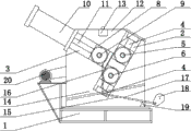
Fig. 1 is front view of the present invention;
Fig. 2 is left view of the present invention;
Fig. 3 is top view of the present invention.
In figure: 1-frame, 2-drive roll groove, 3-driven voller groove, 4-bearing, 5-upper drive roll, 6-lower drive roll, 7 gears, 8-slide block, 9-driven voller, 10-hydraulic jack, 11-piston head, 12-charging aperture, 13-photoelectric induction device, 14-discharging opening, 15-automatic material blocking device, 16-material blocking rod, 17-connecting rod, 18-cam mechanism, 19-support, 20-motor, 21-belt, 22-gearbox.
The specific embodiment
Referring to Fig. 1, Fig. 2, Fig. 3, the present invention is the hot straightener of a kind of cross wedge rolling multi-step shaft parts, have frame 1, particularly: frame 1 each side has the driven voller groove 3 that a groove of the drive roll from the horizontal by 60 ° of angles 2 is vertical with drive roll groove 2 middle parts with, article two, two bearings with bearing 4 of upper and lower symmetry respectively are housed in drive roll groove 2, on the interior corresponding upper bracket 2 of left and right drive roll groove 2, drive roll 5 is housed, lower drive roll 6 is housed on undersetting 2, and described upper and lower drive roll 5 and an end of 6 connect by gear 7 engagements, in described two driven voller grooves 3, a slide block with bearing 8 respectively is housed, on the interior corresponding slide block 8 of left and right driven voller groove 3, driven voller 9 is housed, the upper end of described two slide blocks 8 all is connected with hydraulic cylinder piston head 10, slide block 8 can slide up and down along driven voller groove 3, when slide block 8 is positioned at driven voller groove 3 lowermost end, driven voller 9 and two drive rolls 5 and 6 line between axle center in twos form the equilateral triangle structure, described drive roll 5 and 6, driven voller 9 all are designed to the Step Shaft structure, its Step Shaft structure with treat that the alignment Step Shaft is for the structure of mutually coincideing, that is: the necked part of drive roll 5 and 6, driven voller 9 with treat that the step part of alignment Step Shaft matches, the step part of drive roll, driven voller with treat that the necked part of alignment Step Shaft matches, above frame, position in the middle of corresponding driven voller 9 and upper drive roll 5, be provided with charging aperture 12, charging aperture 12 places are provided with photoelectric induction device 13, the external hydraulic jack controller of photoelectric induction device 13, in frame 1 bottom, the below of three rollers is provided with the discharging opening 14 under oblique, and corresponding workpiece discharging opening 14 places are provided with two automatic material blocking devices 15 in frame 1 bottom, this automatic material blocking device comprises material blocking rod 16, connecting rod 17 and cam mechanism 18, material blocking rod 16 is between lower drive roll 6 and driven voller 9, connecting rod 17 connects material blocking rod 16 and cam mechanism 18, the support 19 of incorporating mill seat 1 bottom is hinged, cam mechanism 18 comprises cam and actuated by cams motor (not shown), the external photoelectric induction device of actuated by cams motor, frame 1 one wing bases are provided with motor 20, and motor 20 connects gearbox 22 by belt 21, and the output shaft of gearbox 22 connects with one of them drive roll 5 or 6.
Gap described in the present embodiment between two drive rolls 5 and 6 peaks is 0.5~1mm.
Drive roll described in the present embodiment 5 and 6 rotating speed are 20~25r/min, and the alignment time of every workpiece is 5~10s, also can be according to the concrete alignment effect proper extension alignment time.
Drive roll 5 described in the present invention and 6 and the structure of driven voller 9 be that the alignment effect is remarkable according to the structure specialized designs for the treatment of the alignment Step Shaft, during the Step Shaft of each production different model, only need to change corresponding drive roll, driven voller gets final product.Step Shaft after the hot straightener alignment of the present invention does not need follow-up cold school more than 80%, can meet the product quality requirement, only less than 20% product because its formation be bent into the axle journal bending that eave tile is curved or spacing is very little, just need to put on a small quantity school, to meet the product quality requirement.Use of the present invention, not only increased substantially the quality of product, also reduced the percent defective of product, also greatly improved production efficiency.
Claims (3)
1. the hot straightener of cross wedge rolling multi-step shaft parts, have frame, it is characterized in that: frame each side has the driven voller groove that a groove of the drive roll from the horizontal by 60 ° of angles is vertical with drive roll groove middle part with, article two, two bearings with bearing of upper and lower symmetry respectively are housed in the drive roll groove, on the interior corresponding upper bracket of left and right drive roll groove, drive roll are housed, lower drive roll is housed on undersetting, an end of described upper and lower drive roll meshes connection by gear, in described two driven voller grooves, a slide block with bearing respectively is housed, on the interior corresponding slide block of left and right driven voller groove, driven voller is housed, the upper end of described two slide blocks all is connected with the hydraulic cylinder piston head, slide block can slide up and down along the driven voller groove, when slide block is positioned at driven voller groove lowermost end, driven voller and two the drive rolls line between axle center in twos form the equilateral triangle structure, described drive roll, driven voller all are designed to the Step Shaft structure, its Step Shaft structure with treat that the alignment Step Shaft is for the structure of mutually coincideing, that is: the necked part of drive roll, driven voller with treat that the step part of alignment Step Shaft matches, the step part of drive roll, driven voller with treat that the necked part of alignment Step Shaft matches, above frame, position in the middle of corresponding driven voller and upper drive roll, be provided with charging aperture, the charging aperture place is provided with photoelectric induction device, the external hydraulic jack controller of photoelectric induction device, in the frame bottom, the below of three rollers is provided with the discharging opening under oblique, and corresponding workpiece discharging opening place is provided with two automatic material blocking devices in the frame bottom, this automatic material blocking device comprises material blocking rod, connecting rod and cam mechanism, material blocking rod is between lower drive roll and driven voller, connecting rod connects material blocking rod and cam mechanism, the support of incorporating mill seat bottom is hinged, cam mechanism comprises cam and actuated by cams motor, the external photoelectric induction device of actuated by cams motor, frame one wing base is provided with motor, and motor connects gearbox by belt, and the output shaft of gearbox connects with one of them drive roll.
2. the hot straightener of a kind of cross wedge rolling multi-step shaft parts according to claim 1, it is characterized in that: the gap between described two drive roll peaks is 0.5~1mm.
3. the hot straightener of a kind of cross wedge rolling multi-step shaft parts according to claim 1, it is characterized in that: the rotating speed of described drive roll is 20~25r/min, the alignment time of every workpiece is 5~10s.
Priority Applications (1)
| Application Number | Priority Date | Filing Date | Title |
|---|---|---|---|
| CN201310469309.0A CN103480699B (en) | 2013-10-10 | 2013-10-10 | The hot straightener of cross wedge rolling multi-step shaft parts |
Applications Claiming Priority (1)
| Application Number | Priority Date | Filing Date | Title |
|---|---|---|---|
| CN201310469309.0A CN103480699B (en) | 2013-10-10 | 2013-10-10 | The hot straightener of cross wedge rolling multi-step shaft parts |
Publications (2)
| Publication Number | Publication Date |
|---|---|
| CN103480699A true CN103480699A (en) | 2014-01-01 |
| CN103480699B CN103480699B (en) | 2015-12-30 |
Family
ID=49821483
Family Applications (1)
| Application Number | Title | Priority Date | Filing Date |
|---|---|---|---|
| CN201310469309.0A Active CN103480699B (en) | 2013-10-10 | 2013-10-10 | The hot straightener of cross wedge rolling multi-step shaft parts |
Country Status (1)
| Country | Link |
|---|---|
| CN (1) | CN103480699B (en) |
Cited By (2)
| Publication number | Priority date | Publication date | Assignee | Title |
|---|---|---|---|---|
| CN105689453A (en) * | 2016-04-25 | 2016-06-22 | 安徽省合肥汽车锻件有限责任公司 | Automatic correcting device and automatic correcting method for shaft hot forging part |
| CN107999571A (en) * | 2017-12-30 | 2018-05-08 | 盛瑞传动股份有限公司 | A kind of camshaft coalignment |
Citations (7)
| Publication number | Priority date | Publication date | Assignee | Title |
|---|---|---|---|---|
| JPH04270012A (en) * | 1991-02-26 | 1992-09-25 | Kawasaki Steel Corp | Straightening machine with width changeable roller |
| CN2410057Y (en) * | 2000-01-17 | 2000-12-13 | 李传斌 | Rolled straightening machine for wedge lateral rolling shafts |
| CN201143530Y (en) * | 2007-11-28 | 2008-11-05 | 朱传宝 | Air-pressure brake heat straightening machine |
| CN201760477U (en) * | 2010-09-15 | 2011-03-16 | 莱芜市金辰楔横轧轴件有限公司 | Cross wedge rolling shaft part straightener with anti-end breaking and anti-seize device |
| CN201791783U (en) * | 2010-09-12 | 2011-04-13 | 赣州汇众精密锻造有限责任公司 | Straightening device of cross wedge rolling shafts |
| CN202045210U (en) * | 2011-01-29 | 2011-11-23 | 河南中轴股份有限公司 | Wedge cross-rolled shaft thermal straightening machine |
| CN203526259U (en) * | 2013-10-10 | 2014-04-09 | 湖北新冶钢汽车零部件有限公司 | Cross wedge rolling multi-stepped-shaft part heat-straightening machine |
-
2013
- 2013-10-10 CN CN201310469309.0A patent/CN103480699B/en active Active
Patent Citations (7)
| Publication number | Priority date | Publication date | Assignee | Title |
|---|---|---|---|---|
| JPH04270012A (en) * | 1991-02-26 | 1992-09-25 | Kawasaki Steel Corp | Straightening machine with width changeable roller |
| CN2410057Y (en) * | 2000-01-17 | 2000-12-13 | 李传斌 | Rolled straightening machine for wedge lateral rolling shafts |
| CN201143530Y (en) * | 2007-11-28 | 2008-11-05 | 朱传宝 | Air-pressure brake heat straightening machine |
| CN201791783U (en) * | 2010-09-12 | 2011-04-13 | 赣州汇众精密锻造有限责任公司 | Straightening device of cross wedge rolling shafts |
| CN201760477U (en) * | 2010-09-15 | 2011-03-16 | 莱芜市金辰楔横轧轴件有限公司 | Cross wedge rolling shaft part straightener with anti-end breaking and anti-seize device |
| CN202045210U (en) * | 2011-01-29 | 2011-11-23 | 河南中轴股份有限公司 | Wedge cross-rolled shaft thermal straightening machine |
| CN203526259U (en) * | 2013-10-10 | 2014-04-09 | 湖北新冶钢汽车零部件有限公司 | Cross wedge rolling multi-stepped-shaft part heat-straightening machine |
Cited By (2)
| Publication number | Priority date | Publication date | Assignee | Title |
|---|---|---|---|---|
| CN105689453A (en) * | 2016-04-25 | 2016-06-22 | 安徽省合肥汽车锻件有限责任公司 | Automatic correcting device and automatic correcting method for shaft hot forging part |
| CN107999571A (en) * | 2017-12-30 | 2018-05-08 | 盛瑞传动股份有限公司 | A kind of camshaft coalignment |
Also Published As
| Publication number | Publication date |
|---|---|
| CN103480699B (en) | 2015-12-30 |
Similar Documents
| Publication | Publication Date | Title |
|---|---|---|
| CN102873511A (en) | Method for radially rolling and forming ring piece with three steps and complicated section | |
| CN105107866A (en) | Thermal shaping method and device of high-strength sharp-corner square rectangular tube | |
| CN104415968A (en) | Hot-rolling high-speed tool steel bar and wire producing process | |
| CN111672902A (en) | Multifunctional test rolling mill capable of rolling special-shaped raw materials | |
| CN103480699B (en) | The hot straightener of cross wedge rolling multi-step shaft parts | |
| CN103230943A (en) | Method for improving bending of head portion of medium plate | |
| CN203526259U (en) | Cross wedge rolling multi-stepped-shaft part heat-straightening machine | |
| CN103433276B (en) | Profile steel rolling production line and production method thereof | |
| CN104722578A (en) | Rolling device for rod piece forging blank and rod piece forming method | |
| CN204620637U (en) | The rolling device of rod member forging blank | |
| CN204620715U (en) | A kind of system being applicable to production in enormous quantities multiple section shaped metal wire rod | |
| CN201150936Y (en) | Novel conveyor roller of aluminum sheet hot milling machine | |
| CN104308544B (en) | Scrap-free machining technology and device for lift truck scissor arm material | |
| CN101215626B (en) | Continuous heat treatment method for angle steel and angle steel manufacturing method | |
| CN203448392U (en) | Section steel rolling production line | |
| CN204584158U (en) | A kind of sheet material compound roll forming machine | |
| CN107470398B (en) | Online automatic correcting device of opening symmetry clod wash section bar | |
| CN209476914U (en) | A kind of high-hardness stainless steel band process units | |
| CN204220617U (en) | A kind of steekle mill production line preparing roughing mill | |
| CN106111724A (en) | Rotary multifunctional shaped device is used in a kind of forging | |
| CN103978350A (en) | Manufacturing method of flange sliding block blank profile | |
| CN205043113U (en) | A apparatus for producing is forged to continuous casting for taking extrude type of moulding | |
| CN207668229U (en) | A few shape steel plate forming equipment | |
| CN203048114U (en) | Novel specially shaped hot steel billet turning device | |
| CN205165687U (en) | Big modulus major diameter roller gear hot rolling shaper |
Legal Events
| Date | Code | Title | Description |
|---|---|---|---|
| C06 | Publication | ||
| PB01 | Publication | ||
| C10 | Entry into substantive examination | ||
| SE01 | Entry into force of request for substantive examination | ||
| C14 | Grant of patent or utility model | ||
| GR01 | Patent grant |