CN103453831A - Rotational clearance measurement system and method of operation - Google Patents
Rotational clearance measurement system and method of operation Download PDFInfo
- Publication number
- CN103453831A CN103453831A CN2013102101731A CN201310210173A CN103453831A CN 103453831 A CN103453831 A CN 103453831A CN 2013102101731 A CN2013102101731 A CN 2013102101731A CN 201310210173 A CN201310210173 A CN 201310210173A CN 103453831 A CN103453831 A CN 103453831A
- Authority
- CN
- China
- Prior art keywords
- probe
- gap
- electrode
- condenser type
- rotating member
- Prior art date
- Legal status (The legal status is an assumption and is not a legal conclusion. Google has not performed a legal analysis and makes no representation as to the accuracy of the status listed.)
- Pending
Links
Images


Classifications
-
- G—PHYSICS
- G01—MEASURING; TESTING
- G01B—MEASURING LENGTH, THICKNESS OR SIMILAR LINEAR DIMENSIONS; MEASURING ANGLES; MEASURING AREAS; MEASURING IRREGULARITIES OF SURFACES OR CONTOURS
- G01B7/00—Measuring arrangements characterised by the use of electric or magnetic techniques
- G01B7/14—Measuring arrangements characterised by the use of electric or magnetic techniques for measuring distance or clearance between spaced objects or spaced apertures
-
- G—PHYSICS
- G01—MEASURING; TESTING
- G01B—MEASURING LENGTH, THICKNESS OR SIMILAR LINEAR DIMENSIONS; MEASURING ANGLES; MEASURING AREAS; MEASURING IRREGULARITIES OF SURFACES OR CONTOURS
- G01B5/00—Measuring arrangements characterised by the use of mechanical techniques
- G01B5/14—Measuring arrangements characterised by the use of mechanical techniques for measuring distance or clearance between spaced objects or spaced apertures
-
- G—PHYSICS
- G01—MEASURING; TESTING
- G01B—MEASURING LENGTH, THICKNESS OR SIMILAR LINEAR DIMENSIONS; MEASURING ANGLES; MEASURING AREAS; MEASURING IRREGULARITIES OF SURFACES OR CONTOURS
- G01B7/00—Measuring arrangements characterised by the use of electric or magnetic techniques
- G01B7/14—Measuring arrangements characterised by the use of electric or magnetic techniques for measuring distance or clearance between spaced objects or spaced apertures
- G01B7/144—Measuring play on bearings
-
- F—MECHANICAL ENGINEERING; LIGHTING; HEATING; WEAPONS; BLASTING
- F01—MACHINES OR ENGINES IN GENERAL; ENGINE PLANTS IN GENERAL; STEAM ENGINES
- F01D—NON-POSITIVE DISPLACEMENT MACHINES OR ENGINES, e.g. STEAM TURBINES
- F01D11/00—Preventing or minimising internal leakage of working-fluid, e.g. between stages
- F01D11/08—Preventing or minimising internal leakage of working-fluid, e.g. between stages for sealing space between rotor blade tips and stator
- F01D11/14—Adjusting or regulating tip-clearance, i.e. distance between rotor-blade tips and stator casing
- F01D11/20—Actively adjusting tip-clearance
Abstract
A radial clearance measurement system is provided. The radial clearance measurement system comprises a radial clearance sensor that is relatively insensitive to axial movement of an object rotating relative to the radial clearance sensor. In one embodiment, the radial clearance sensor includes an electrode having a relatively constant overlap area over the range of axial movement of the object.
Description
Background technology
Various types of rotating machineries be included in the member that rotates in the space limited by static component or shell (such as, blade or movable vane).In this machinery, for various operation reasons, can be interested, spacing or gap that monitoring maintains between rotating member and static component.For example, steam turbine has near the rotation movable vane be configured in carriage.Gap between rotation movable vane and carriage is because the various modes of operation of the oxidation such as temperature variation, movable vane end etc. change.Desirable, maintain space or the gap between rotation movable vane and carriage in steam turbine operating period.
Typically, turbomachinery has the heat growth occurred on rotating member and static component.This expansion can be axially and radially occur on both, and typically, and expectation minimizes for example, gap between rotating member and housing (, shell) (such as, radial play).Yet design and operation change can affect determining of this gap measurement.A kind of is to shut down via soft friction pin utilization the measurement of carrying out during the period (that is, off-line) for the method for determining the minimum clearance value.This off-line measurement can be not suitable for understanding and optimizing the gap in the turbine system moved.
Summary of the invention
In one embodiment, provide a kind of condenser type gap probe.Condenser type gap probe comprises probe body and is engaged in the electrode in probe body.Electrode comprises the rectangle head, and it has the length that is selected to the axially movable scope that is greater than the member rotated with respect to condenser type gap probe.
In yet another embodiment, provide a kind of radial play measuring system.The radial play measuring system comprises being configured in to have
in additionone or more fixed reference feature on the rotating member of continuous surface geometric configuration.Rotating member suffers the axial displacement around the certain limit of the axis of its rotation along rotating member.System also comprises the radial play sensor be configured on the housing relatively static with respect to the rotating member maintenance.The radial play sensor arrangement becomes to generate the signal of the electric capacity between indication radial play sensor and rotating member.The radial play sensor comprises the electrode with rectangle head.The rectangle head is greater than the scope of the axial displacement of rotating member along the length of axis.System also comprises and is configured to processing signals to estimate the processing unit in the gap between rotating member and housing.
In additional embodiment, provide a kind of gap sensor assembly.The gap sensor assembly comprises the radial play sensor that has the probe body that comprises the keyed jointing feature and be engaged in the electrode in probe body, and electrode comprises the rectangle head.The gap sensor assembly also comprises the installation component that is configured to keep the gap sensor probe.Installation component comprises cylinder and mounting structure, and this cylinder comprises that complementary keyed jointing feature makes the restriction probe body be engaged in cylinder, and this mounting structure is configured to attach to the housing of rotary machine assembly.Mounting structure comprises engagement features, and its complementary characteristic with the rotary machine assembly is corresponding, makes when being installed on the rotary machine assembly, and the major axis of the rectangle head of electrode is parallel to the rotation relevant to the rotary machine assembly.
A kind of condenser type gap probe, it comprises: probe body; And being engaged in the electrode in probe body, electrode comprises: electrode head, it has the basically identical overlapping region in the axially movable scope of the member with respect to the probe rotation of condenser type gap.
Preferably, electrode comprises hollow electrode.
Preferably, condenser type gap probe comprises the cable that is connected in probe body.
Preferably, condenser type gap probe comprises the conductor that makes cable be connected in electrode.
Preferably, probe body comprises that electrode is engaged in ceramic head wherein.
Preferably, probe body comprises: two or more metal master parts that are combined together; And the ceramic head parts that are matched with the metal master part, wherein, electrode is engaged in the ceramic head parts.
Preferably, electrode head has and is selected to the width that is less than the corresponding width that is arranged on the fixed reference feature on member.
Preferably, condenser type gap probe comprises the fistulae that the inner chamber that makes probe body is connected with external environment condition.
Preferably, condenser type gap probe sealing with being sealed.
Preferably, condenser type gap probe comprises the installation component that is configured to keep probe body and probe body is installed on to the housing of rotary machine assembly, wherein, installation component is configured to, under the configuration of limited quantity, probe body is installed on to housing, and the major axis of each the constraint electrode head in configuration is parallel to the rotation of rotary machine assembly.
A kind of radial play measuring system, it comprises: one or more fixed reference feature, and it is configured on the rotating member with other continuous surface geometric configuration, wherein, rotating member suffers along the axial displacement of the certain limit of axis, and rotating member rotates around axis; The radial play sensor, it is configured on the housing relatively static with respect to the rotating member maintenance, wherein, the radial play sensor arrangement becomes to generate the signal of the electric capacity between indication radial play sensor and rotating member, the radial play sensor comprises: the electrode with rectangle head, wherein, the rectangle head along the length of axis corresponding to or be greater than the scope of the axial displacement of rotating member; Processing unit, it is configured to processing signals to estimate the gap between rotating member and housing.
Preferably, the radial play sensor arrangement becomes to generate signal when rotating member moves with respect to housing.
Preferably, the radial play measuring system also comprises: driving source, and it is configured to the supply of gap sensor radially pumping signal; And phase detectors, it is configured to detect a plurality of reflected signals and carries out repeatedly phase measurement to determine the phase place between each and the corresponding pumping signal in reflected signal.
Preferably, one or more fixed reference feature comprises the first notch with first degree of depth and the second notch with second degree of depth different from first degree of depth.
Preferably, the radial play measuring system also comprises gap control unit, and it is connected in processing unit and controls the gap between rotating member and housing for the gap based on being estimated by processing unit.
Preferably, the width of rectangle head is less than the corresponding width of one or more fixed reference feature.
A kind of gap sensor assembly, it comprises: the radial play sensor, it comprises: the probe body that comprises the keyed jointing feature; Be engaged in the electrode in probe body, electrode comprises the rectangle head; Be configured to keep the installation component of gap sensor probe, installation component comprises: cylinder, and it comprises complementary keyed jointing feature, makes the restriction probe body be engaged in cylinder; Mounting structure, it is configured to attach to the housing of rotary machine assembly, wherein, mounting structure comprises engagement features, its complementary characteristic with the rotary machine assembly is corresponding, make when being installed on the rotary machine assembly, the major axis of the rectangle head of electrode is parallel to the rotation relevant to the rotary machine assembly.
Preferably, mounting structure comprises flange, and wherein, engagement features comprises and is configured to limit a plurality of bolts hole that installation component is installed on the orientation of rotary machine assembly.
Preferably, installation component comprises two or more separable.
Preferably, installation component comprises the split washer assembly.
The accompanying drawing explanation
When the reference accompanying drawing is read following detailed description, these and other feature of the present invention, aspect and advantage will become better understood, and in this accompanying drawing, same mark spreads all over accompanying drawing and means same parts, wherein:
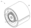
Fig. 1 is the diagram perspective drawing according to the steam turbine with clearance measurement system of aspect of the present disclosure;
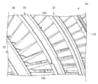
Fig. 2 is the local diagram perspective drawing according to the rotation movable vane of the steam turbine of Fig. 1 of aspect of the present disclosure;
Fig. 3 shows the skeleton view had according to the steam turbine of Fig. 1 for the clearance measurement system of measuring the gap between rotation movable vane and housing of aspect of the present disclosure;
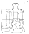
Fig. 4 wherein can be used according to aspect of the present disclosure the sectional view of a part of steam turbine of Fig. 3 of this clearance control technology;
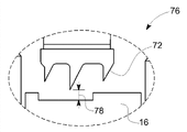
Fig. 5 is the detailed sectional view according to Fig. 4 of aspect of the present disclosure;
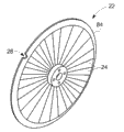
Fig. 6 shows the rotating member level with notch according to aspect of the present disclosure;
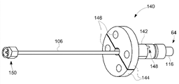
Fig. 7 has described the skeleton view according to the probe end of the radial play sensor of aspect of the present disclosure;
Fig. 8 has described the cut-open view according to the probe end of the radial play sensor of aspect of the present disclosure;
Fig. 9 has described the cut-open view according to the probe end that comprises blow-by tube of aspect of the present disclosure;
Figure 10 has described according to the installation component of aspect of the present disclosure and probe end;
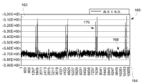
Figure 11 describes the capacitance measurements of passing in time according to aspect of the present disclosure with curve map; And
Figure 12 is the diagram figure according to the clearance measurement system of aspect of the present disclosure.
Embodiment
As discussed in this article, the crucial criterion of the performance of rotary machine (such as, steam turbine) can be the time reached such as the operating conditions of the mode of operation corresponding with generating.In order to minimize this time, can assess axially and/or the radial play data.As discussed in this article, can adopt one or more gap sensor that real-time gap data is provided and allow in during starts monitoring.The data of utilizing gap sensor to obtain can be used for monitoring and purpose of appraisals, and/or can be integrated improved ability to be provided or to improve reliability and efficiency with turbine control system.
For this consideration, the disclosure relates to the use to insensitive one or more condenser type radial play sensor of axial dipole field.Especially, because main overlapping region and the distance between the measured zone of the measure portion based on rotating member and sensor of capacitance measurements, so can cause the gap evaluated error about the uncertainty of overlapping region.For this consideration, the radial play sensor utilization of discussing herein is to the insensitive end of the axial dipole field occurred during normal system operation between rotating member and static component and target geometry.Because the radial play sensor of describing provides the radial play data of the correlated error without the axial dipole field of being attributable to, so can realize the processing of significantly simplifying.In addition, with a plurality of sensing datas wherein, must interrelatedly with other application that obtains gap, compare, the disclosure realizes the independent independent processing of radial play data.
Before the various embodiment that discuss insensitive radial play sensor of axial dipole field, the initial description is suitable for the rotating machinery that uses together with this sensor and the various examples of method for sensing, in order to be convenient to the explanation subsequently of gap sensor and use thereof.As will be recognized, therefore the instantiation of system and equipment only for convenience of explanation and context is provided and provides, and is not intended to the scope of the present disclosure is limited to disclosed example.On the contrary, the gap sensor of discussing herein can be combined with any suitable rotating machinery, wherein, measure the radial play of rotating member with respect to another member, and expectation is insensitive to axially-movable.
As discussed in this article, the embodiment of this sensor and measurement can be used for providing various rotary systems (such as, steam turbine, pump, compressor, generator, turbine engine (for example, aircraft turbine engine), there is the machine of rotating member etc.) in two objects between the accurate measurement of radial play.With reference now to accompanying drawing,, Fig. 1 shows the steam turbine 10 of the clearance measurement system 12 of the radial play between two objects that have for measuring steam turbine 10.In the illustrated embodiment, clearance measurement system 12 is configured to measure rotating member 14 static housing relative to comparing with rotating member when rotating member operates of steam turbine 10 or the radial play between guard shield 16.
Turn to Fig. 2, show the rotating member local diagram perspective drawing of (such as, the rotation movable vane assembly 20 of the steam turbine of Fig. 1).In the illustrated embodiment, rotation movable vane assembly 20 is arranged in housing 16 under having not at the same level 22 configuration.It should be noted that to be configured in the housing 16 of level around 22 not shown, in order to allow the visual of movable vane assembly 20.Level 22 in housing 16 comprises along the mutual longitudinally-spaced a plurality of rotation movable vanes 24 of the length (and rotation) of the steam turbine 10 of Fig. 1.In addition, rotation movable vane 24 is radially spaced (as Fig. 1 is described) with housing 16.In other words, the external diameter of rotation movable vane 24 is less than the internal diameter of housing 16.Therefore, the relative little gap of existence between the inside surface of periphery and the housing 16 of rotation movable vane 24.In addition, except the clearance control feature (for example, notch 28) that discusses in detail below in addition, rotation movable vane 24 forms continuous circular structure (being depicted as herein the blade with isolated notch 28) around the rotation of rotation movable vane 24.In one embodiment, notch 28 can have the axial length length of the direction of rotation (that is, along) of approximate 0.050 inch to 0.200 inch (approximate 1.27mm to 5.08mm).As will be recognized, the configuration of notch 28 can change and can comprise notch wherein have the enforcement of generally linear or straight flange and wherein notch edge and/or turning comprises a certain flexibility that other is implemented, comprise that wherein notch 28 is the embodiment of partial circle.
In this embodiment, clearance measurement system 12 (seeing Fig. 1) is configured to measure for example, radial play between housing 16 (that is, relatively static member) and rotating member 24 (, rotation movable vane).In certain embodiments, clearance measurement system 12 can be used for measuring housing in generator or other rotating machinery and the gap between rotating member.In fact, there is the measurement of the radial play in other rotating machinery of the rotating member be radially spaced with static or other carriage or housing member in the scope of the present disclosure.
As discussed in this article, clearance measurement system 12 is configured to convert time dependent capacitance measurements to based on galvanic capacitance measurements between housing 16 and rotating member 14.At least one fixed reference feature or the structure (for example, notch 28, groove, slit etc.) of clearance measurement system 12 based on distinguishing on the part that stands capacitance measurement of rotating member carried out this conversion.For example, fixed reference feature or structure can be interrupted the continuity of the other continuous surface geometric configuration (for example, continuous circular geometric configuration) of rotating member around rotation.This time dependent capacitance measurements is for estimated rotor member 14 and the radial play between housing 16 on every side, as will be described below in more detail.
Turn to Fig. 3, show rotary machine (such as, steam turbine 10 as shown in Figure 1), it is incorporated to the radial play measuring system 12 of discussing as in this article.Steam turbine 10 comprises the rotating member 14 with the rotor 52 be arranged on axle 54.A plurality of whirling motion blades (for example, movable vane 24) invest rotor 52.In operation, blade suffers the steam 58 of high temperature and high pressure, and this makes blade around axis 60 rotations.Blade (that is, movable vane 24) is rotating in blade radial and the housing 16 of circumferentially locating or guard shield.There is relative little gap between blade and housing 16, so that the rotation of blade in housing 16 also prevents the excessive leakage of working fluid (that is, steam) between blade and housing 16 simultaneously.The sensor of each radial play sensor module 12 or probe end 64 are configured in static guard shield 62 and circumferentially configure around static guard shield 62.In the illustrated embodiment, radial play sensor module 12 comprises capacitance probe.As explanation below, each in sensor module 12 be configured to generate the indication blade at corresponding circumferential position place the signal with respect to the radial position of housing 16.
With reference now to Fig. 4,, the sectional view for the part 70 of the steam turbine 10 of Fig. 3 is shown.In the illustrated embodiment, the blade type seal is shown, wherein, edge or the end 56 of rotating member 14 (such as, level 22) comprise filling tooth in the groove 74 be engaged on the interior week that is arranged on housing 16 or sealing tooth 72.In one embodiment, clearance measurement system 12 (seeing Fig. 1) can be connected in housing 16, for measuring level 22 the circumferential edge of rotating member 14 or the radial play between end 56 and housing 16.Turn to Fig. 5, the detailed sectional view of the part 76 of the housing 16 of the steam turbine 10 of depiction 4 and edge (for example, tooth 72).As shown, the radial play between sealing tooth 72 and housing 16 is meaned by Reference numeral 78.
In certain embodiments, due to the difference of the coefficient of thermal expansion of housing 16 and rotor 52, therefore thereby exist radial play 78 can be reduced to zero possibility that causes sealing the interference between tooth 72 and groove 74.Therefore, in certain embodiments, probe is mounted to recessed a little with respect to the surface of guard shield 62, in order to prevent this interference event (that is, scraping) during movable vane 24 rotations.Similarly, probe (with probe end 64) can be configured to during operation with respect to the past distance configurable or that set of pulling back in the surface of guard shield 62, to prevent this interference event.In this enforcement, probe also can be pulled back with respect to the surface of guard shield 62 is past between erecting stage, so that the placement of the various members of system and connection.
The disclosure allows the on-line measurement of radial play 78, and it can be incorporated in Closed-loop Control Strategy radial play is remained on to the value place in the acceptable limit.Control strategy can comprise for example thermal actuation of housing 16, thereby suitably expands when its gap between housing 16 and sealing tooth 72 is reduced.In this embodiment, thermal actuator utilizes thermal expansion character to produce movement or the expansion of housing 16 with respect to rotation movable vane 24.
The aspect that turns to radial play to measure, as discussed in this article, measure two electric capacity between object.The separation (that is, gap) of this capacitance measurements based between the overlapping of surf zone and two objects both.For example, in one embodiment, the edge 56 of the rotating member (for example, level 22) of the electric capacity between the edge of rotating member 14 or end 56 and housing based on standing to measure and the radial play 78 that is embedded in the sensor in housing 16 or pops one's head between end 64.When rotating member 14 radially expands, along the edge of level 22 or sealing tooth 72 and the radial play between housing 16 78 of end 56, change.These variations of radial play 78 will cause the variation of the electric capacity of measurement.As discussed in this article, the variation of electric capacity can be relevant to radial displacement, and therefore can obtain the radial play measurement.Will be further described below the measurement via the radial play 78 of clearance measurement system 12.
Turn to Fig. 6, for example, for the part (, level 22) of the rotating member 14 that uses at steam turbine, illustrate and there is notch 28 (that is, fixed reference feature or structure).In the illustrated embodiment, rotating part comprises circumferentially connection or attached to form a plurality of blades or the movable vane 24 at the continuous and circular edge 84 around the cardinal principle of rotation.Circumferential edge 84 also comprises one or more notch 28 or interrupts successional other fixed reference feature at other continuous circular edge 84.The example of suitable fixed reference feature comprises recess, such as indenture, notch, groove, slit etc.In other embodiments, can have two or more notches 28 on edge 84, and some notch 28 can have the different qualities degree of depth with respect to the remainder at edge 84.For example, as depicted in Figure 2 and as discuss in example subsequently in this article, edge 84 can be set to have the knive-edge seal along two (or more) notches 28 of circumferential edge 84, wherein, at least two different depths that have with respect to the remainder at edge 84 in notch 28.
In operation, the sensor module 12 (seeing Fig. 3) that attaches to housing 16 generates the signal corresponding with electric capacity in measurement between rotating member 14 (or a specific order 22 of rotating member 14) and housing 16.The electric capacity of being measured by sensor module 12 and then can be processed, to estimate the radial play between housing 16 and rotating member 14 or corresponding stage 22.In certain embodiments, the end 64 of sensor module 12 be configured to rotating member 14 during measuring with respect to housing 16 move axially or displacement basically insensitive.
Especially, as pointed in the above about axial displacement, the measurement result of for example, electric capacity between housing 16 and rotating member 14 (, level 22) is overlapping based between these structures at least in part.On mutual degree between edge in capacitance measurements based on probe end 64 and rotating member 14 or circumferential district, the overlapping region between the edge of probe end 64 and measurement is the factor in capacitance measurement.Therefore, the uncertainty about the overlapping region between probe end 64 and the sensed part of rotating member 14 can cause the gap evaluated error.
For example, in classic method, the sensing of probe end 64 partly can be circular (still also can adopt other non-elongated configuration, such as triangle or trapezoidal probe end).In this enforcement, when the knive-edge seal formed by tooth 72 axially moves with respect to housing 16 during operation, tooth 72 and the overlapping region be configured between the circular probe end in housing change.In other words, tooth 72 will make the effective overlapping region between the edge of circular probe end and rotating member change with respect to the axial displacement of circular probe end.Therefore, the precision of the capacitance measurement corresponding with radial play 78 can suffer axial dipole field or the displacement of rotating member 14, to a certain extent, and the effective overlapping region between the measurement marginal portion of this axially-movable change probe end and rotating member 14.
For this uncertainty in the overlapping region between the part that stands to measure that solves sensor probe end 64 and rotating member 14, some embodiment discussed herein utilizes probe end and target geometry, the uncertainty that it reduces or elimination is relevant with overlapping region and therefore insensitive with respect to axial dipole field or the displacement of housing 14 during operation to rotating member 14.
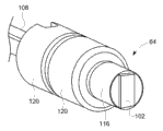
For example, turn to Fig. 7 and Fig. 8, describe the example of an embodiment of the probe end 64 of radial play measuring system 12.In this example, adopt " ailhead " type probe electrode 102 with rectangle end.For example, in one embodiment, the rectangle end of electrode 102 has that about 200 Mills * 100 Mills (, approximate 5.08mm * 2.54mm) size, wherein, long size is (, length) rotation that is parallel to rotating member 14 extends, and for example, extend than the circumferential edge 84 that stands the part measured that narrow dimension (that is, width) is parallel to rotating member (, level 22).In other embodiments, probe end 64 comprises the electrode 102 of 0.400 inch (approximate 10.16mm) length had vertically.In other enforcement, the electrode 102 at probe end 64 places can have about 2.0 inches (approximate 50.8mm) or less axial length.Substantially, the axial length of the notch 28 on rotating member 14 or other fixed reference feature can be from about 1:2 to about 1:8 with the length breadth ratio of the axial length of probe end 64.
The result of this elongation of the head of electrode 102 is, with respect to the part that stands to measure of rotating member 14 (such as, knive-edge seal), provides in the axial direction basically cross section uniformly.Therefore, the edge 84 of rotating member 14 or other parts will have the overlapping region with respect to the substantial constant of electrode 102 with respect to the axial dipole field of the head of electrode 102, thereby cause the axial dipole field relative insensitivity of 12 pairs of rotating members 14 of radial play measuring system.In addition, axial insensitivity due to the clearance measurement system 12 with the end 64 of popping one's head in as described, therefore the variation of the electric capacity of measuring can be most of or individually owing to the variation of radial play 78, this is because the overlapping region maintenance between the monitoring edge 84 of electrode 102 and rotating member 14 is relative constant.In some is implemented, the head of electrode 102 is the same long or longer than it with expection or the potential axial displacement at the edge 84 that stands to measure in the length be parallel on the direction of rotation.Yet in certain embodiments, the head of electrode 102 can slightly be shorter than expection or the potential axial displacement that stands the edge 84 measured being parallel to length on the direction of rotation.In such an embodiment, owing to effectively allowing capacitance probe to monitor the relevant edge field in the zone that is slightly larger than the actual area relevant to electrode 102, therefore electrode 102 still provides effectively constant overlapping region.
In addition, will be appreciated that, although via example, the rectangular electrode head is discussed in this article, can adopt other electrode head shape, effectively constant as long as overlapping region vertically spreads all over the scope of potential axial displacement.For example, at some, other can be configured as square or ellipse in implementing to the head of electrode 102, as long as the overlapping region between the edge 84 of electrode 102 and measurement is effectively constant in the scope of the axial displacement of estimating.
In addition, about other size of the head of electrode 102, notch 28 or other fixed reference feature are arranged in the enforcement on the part that stands to measure (such as, the edge 84 of level 22) of rotating member 14 therein, can be desirable, the width of electrode 102 is less than characteristic of correspondence.For example, notch 28 is arranged in the enforcement on the circumferential edge 84 of rotating member therein, can desirablely be, the width of notch (as radially or upwards measure in week) the certain coefficient of head width in the same direction that surpasses electrode 102 (for example, 20%), make electrode head make progress " cooperation " in week in notch 28 or other architectural feature.In this example, the whole width of electrode head at a time is included in the width of notch 28 or further feature during each rotation of rotating member, guarantees that thus capacitance measurements indication is from electrode 102 to notch 28 or the distance of the bottom surface of further feature.
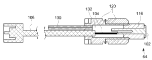
In one embodiment, probe end 64 seals with being sealed, and electrode 102 is hollow electrode with inner hollow diameter (such as, hollow platinum electrode).In other embodiments, electrode 102 can be solid rather than hollow.In fact, the use of hollow electrode can be useful in following application, wherein, expectation reduce to pop one's head between the member of end 64 (such as, at the hard solder junction surface and/or metallized ceramic section locate) structural stress.In addition, in the example of describing, one or more hard solder junction surface is chamfered (seeing the accessory 112 of cutting sth. askew).The hard solder junction surface is for connecting the enforcement of member of the end 64 of pop one's head in therein, and probe can, by hard solder vertically in vacuum drying oven, make gravity and oblique cutting part assist the mobile of liquid solder during manufacture process.
In one embodiment, the cable of connection or line 106 (such as, concentric cable or rigid line) conductor 104 (such as, platinum central electrode) can weld (for example, spot welding 108) in electrode 102.Conductor 104 and cable 106 allows signals to be read and be conveyed to the downstream member from electrode 102, and its processing signals to be to pass in time monitoring electric capacity, as is discussed below.
Via example, utilize platinum center conductor 104, semi-rigid coaxial cable 106 and stainless steel 446 probe body 120 in BAU4 gold nickel hard soldering alloy, 94% molybdenum manganese metal aluminium oxide ceramics (for the ceramic head parts attached), platinum electrode 102, stainless steel sheath 321 to build sensor probe end 64.In some is implemented, can be in ceramic head parts 116 milling groove or other conformal recess, to coordinate the rectangle end of electrode 102.
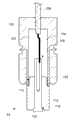
As mentioned in the above, in some is implemented, probe end 64 seals with being sealed.For the airtight sealing on test probe end 64, fistulae 130 (Fig. 9) can be incorporated in the back cavity 132 of probe.In this enforcement, fistulae 130 can be used for vacuumizing for leakproofness to be tested.A this leakproofness thermometrically helium leak rate.For example,, if realize 1 * 10
-8atm cc/ second or lower helium leak rate, leakproofness can be defined as enough.Once complete leak-testing and probe end 64 is defined as sealing with being sealed, fistulae 130 can solderedly seal.
Turn to Figure 10, describe the example of the installation component of the housing 16 for sensor probe being attached to rotary machine.In the embodiment described, installation component 140 is set to split washer.Installation component 140 engages with sensor probe, and provides keyed jointing so that the axial length of rectangular electrode end 102 remains parallel to the axis of turbine rotor.In one embodiment, installation component 140 can be made by the cylinder 142 that is processed with flange 144, and flange 144 has the hole 146 corresponding with threaded hole on housing 16.In one embodiment, thus pair of holes 146 is symmetrical on installation component 140 only to be allowed 0 ° to 180 ° of rotation and prevents that the probe orientation of 90 ° or 270 ° from will not occur.Can arrange with the end 64 of popping one's head on the feature (for example, tab 148) of end of cylinder 142 of complementary characteristic keyed jointing.In one embodiment, probe end 64 is placed on countersunk, and bolt torque provides compressive load on probe end 64.Connector 150 sizes surpass in the enforcement of internal diameter of installation component 140 therein, and installation component 140 can be divided into a plurality of parts (such as, the split washer assembly of describing) and manufacture rather than manufacture integratedly.Alternatively, installation component 150 can be manufactured at first integratedly, but can be such as using electric discharge processing or other suitable method separately.
For the consideration of the aforementioned details about probe and probe end, in some is implemented, as discussed in this article, between housing 16 and rotating member 14, obtain based on galvanic capacitance measurements.As will be recognized, when the radial play between housing 16 and rotating member 14 increases, with the cardinal principle circular edge 84 of rotating member 14 and for example, with the difference between capacitance measurements corresponding to fixed reference feature (, notch 28), will reduce.Similarly, when radial play reduces, this species diversity between capacitance measurements will increase.In other words, the gap between the electric capacity of sensing and housing 16 and rotating member 14 is inversely proportional to.Via example, in one embodiment, if the gap between housing 16 and rotating member 14 doubles, the difference between baseline electric capacity and peak value electric capacity will reduce with 0.5 coefficient.
One or more notch 28 or other fixed reference feature are arranged in the enforcement on the part that stands to measure of rotating member 14 therein, this capacitance measurements can be based on for example, through the pop one's head in fixed reference feature of end 64 or the cycle translation of a plurality of fixed reference feature (, notch 28), being converted to time dependent capacitance measurements.For example, Figure 11 describes the electric capacity 160 of measuring as passed in time by clearance measurement system 12 with curve map, and clearance measurement system 12 has the probe end 64 be embedded in housing 16.The capacitance that the longitudinal axis 162 of capacitance measurement means by sensor module 12 sensings, and transverse axis 164 means the time period.
The baseline 168 of the signal generated by sensor module 12 in the present embodiment, is corresponding to the electric capacity of measuring for the cardinal principle circular edge part 84 of rotating member 14.The peak value of the signal generated by sensor module 12 or raised portion 170, corresponding to the electric capacity of measuring when sensor module 12 is passed through in notch 28 translations, are provided for the interim reference point of the capacitance data 160 of acquisition thus.In some is implemented, as for example, the degree of depth corresponding to fixed reference feature (, notch 28) of the amplitude of the peak value part 170 measured with respect to baseline 168.In other words, difference between the predetermined or known depth of the amplitude of baseline 168 and peak value part 170 and fixed reference feature can be used for determining the gap between rotating machinery operating period (that is, when rotating member rotates with respect to housing) housing 16 and rotating member 14.
In the example of describing, upper curve is described a series of four rotations of the circular edge 84 of the rotating member through being embedded in the probe end 64 in housing 16, and wherein, circular edge 84 comprises two isolated notches 28 with different depth.As will be recognized, the speed of measuring system is by adopting a plurality of notches 28 (or other fixed reference feature) to increase, and this is because for each rotation of rotating member 14, a plurality of differences between the parameter (that is, electric capacity) of acquisition sensing.In certain embodiments, this plurality of difference can be used as the means for self-calibrating clearance measurement system 12.The lower curve of Figure 11 is described the once feature of rotation through the circular edge 84 of the rotating member of probe end 64, and the more detailed view of difference of the electric capacity of observation is provided.The difference of the degree of depth of notch 28 can be observed with the different peak amplitudes 170 relevant from respective slot 28.
For considering above, Figure 12 shows the example of the configuration of the clearance measurement system 12 as discussed in this article.Clearance measurement system 12 comprises the probe with probe end 64, and rectangle or other configuration provided along the electrode 102 of the axial constant overlapping region of rotary machine is provided probe end 64.In addition, signal generator 172 is connected in probe end 64, to probe, to provide input signal.In the illustrated embodiment, signal generator 172 comprises voltage-controlled oscillator (VCO).Come the pumping signal of automatic signal generator 172 to be switched or to be applied to probe end 64 by control in addition by switch 176, but in certain embodiments, switch 176 can not exist.
In addition, amplifier 178 can be connected in signal generator 172, to amplify the input signal received by probe end 64.In the illustrated embodiment, capacitor 180 and phase detectors 174 are connected in probe end 64, for measuring the electric capacity through probe end 64.In addition, directional coupler 190 can be connected in probe end 64, for separating of the incident from corresponding probe end 64 and reflected signal.
In operation, probe end 64 is encouraged with excitation frequency by signal generator 172.Excitation frequency can geometric configuration, static measurement electric capacity and other factors based on line length, electric capacity, probe end 64 be selected.In the present embodiment, phase detectors 174 are configured to detect from the phase differential between the reflected signal of probe end 64 and the pumping signal of carrying out automatic signal generator, with the signal of the electric capacity that generates the representative measurement.Especially, measure the electric capacity through probe end 64 by the phase differential that utilizes capacitor 180 and phase detectors 174 to measure between pumping signal and corresponding reflected signal.
Then, can process the signal generated from probe via processing unit 198.In addition, can follow the tracks of and control via frequency-tracking unit 200 frequency of the pumping signal of automatic signal generator 172.In operation, processing unit 198 receives the signal of the electric capacity of the sensing that representative and rotating member 14 are corresponding with being configured in fixed reference feature on rotating member 14.In addition, the measurement result difference between the electric capacity of processing unit 198 based on for example, from rotating member 14 and fixed reference feature (, notch 28) sensing is estimated the gap between rotating member 12 and housing 16.More specifically, the electric capacity of this sensing is processed, with the pre-sizing based on measurement result difference and fixed reference feature, determines the gap between housing 16 and rotating member 14.
The measurement of the fixed reference feature based on having pre-sizing (for example, notch 28) has reduced the impact of any noise component (noise component) in measurement that the factor by variation of the material character of the drift such as electronic equipment, housing 16 and rotating member 14 etc. causes significantly.In the illustrated embodiment, noise component can show comparably among all measurements, and invalid when estimating the difference of measurement result subsequently.Therefore, in such an embodiment, process the time dependent signal received by processing unit 198, and extract the feature of signal.In this embodiment, the feature of signal comprises baseline values and peak height (corresponding with depth of rebate).In addition, the pre-sizing of the peak height of extraction and notch 28 relatively.Because depending on gap, the notch height of measuring carrys out convergent-divergent, therefore can utilize a kind of definite gap in some methods.Method comprises model or the iunction for curve of look-up table, analysis/based on physics.As described above, can adopt a plurality of this fixed reference features, and processing unit 198 is determined the required gap of convergent-divergent of the measurement that fixed reference feature is provided by the pre-sizing of this fixed reference feature.Therefore, any measuring error (non-temporal evolution or the error slowly changed) of for example within the long time, introducing fixed bias will be eliminated, and this is because utilize the difference of measurement result rather than the absolute value of measurement result to complete processing.
Therefore, by interrupted the continuity of the continuous surface geometric configuration of rotating member 14 by fixed reference feature, clearance measurement system 12 will be converted to time dependent capacitance measurements based on galvanic capacitance measurements between rotating member 14 and housing 16.More particularly, the continuity of interrupting the continuous surface geometric configuration by reference to feature is introduced the spike in the signal produced by capacitance probe, and it can be used for the self-calibrating sensing system and guarantees that measurement result is not affected by signal drift.
As previous discussion, this time dependent capacitance measurements is for estimating the gap between rotating member 14 and housing 16.In certain embodiments, processing unit 198 can adopt look-up table, calibration curve or estimate other technology in gap for the measurement result difference between the electric capacity based on sensing and the pre-sizing that is configured in the reference geometric configuration on rotating member 14.In addition, gap control unit 202 can be connected in processing unit 198, for the gap based on being estimated by processing unit 198, controls the gap between rotating member 14 and housing 16.
The various aspects of method described herein have the practicality in different application.For example, technology described above can be used for measuring rotating member in steam turbine and the gap between stationary member.Technology also can be used at some in other application, for example, and for the static component of measuring generator and the gap between rotating member.As mentioned above, more generally, for at least one fixed reference feature of the continuous surface geometric configuration by based on interrupting rotating member, by based on galvanic capacitance measurements, being converted to time dependent capacitance measurements and providing by sensor for the accurate measurement of the radial play between object between static component and rotating member, method described herein can be favourable.In addition, to even in operation and be provided for the self-calibrating sensing system that the precise gaps of parts is measured within the time period extended, thereby realize the better clearance control of parts when in operation, disclosed embodiment is particularly advantageous.
Although only illustrate in this article and describe some feature of the present invention, those skilled in the art will expect many modifications and variations.Therefore, will understand, the claims intention contains all this modifications and variations that fall in true spirit of the present invention.
Claims (10)
1. pop one's head in a condenser type gap, and it comprises:
Probe body; And
Be engaged in the electrode in described probe body, described electrode comprises:
Electrode head, it has the basically identical overlapping region in the axially movable scope of the member with respect to the probe rotation of described condenser type gap.
2. condenser type according to claim 1 gap probe, is characterized in that, described electrode comprises hollow electrode.
3. condenser type according to claim 1 gap probe, is characterized in that, comprises the cable that is connected in described probe body.
4. condenser type according to claim 3 gap probe, is characterized in that, comprises the conductor that makes described cable be connected in described electrode.
5. condenser type according to claim 1 gap probe, is characterized in that, described probe body comprises that described electrode is engaged in ceramic head wherein.
6. condenser type according to claim 1 gap probe, is characterized in that, described probe body comprises:
Two or more metal master parts that are combined together; And
Be matched with the ceramic head parts of described metal master part, wherein, described electrode is engaged in described ceramic head parts.
7. condenser type according to claim 1 gap probe, is characterized in that, described electrode head has and is selected to the width that is less than the corresponding width that is arranged on the fixed reference feature on described member.
8. condenser type according to claim 1 gap probe, is characterized in that, comprises the fistulae that the inner chamber that makes described probe body is connected with external environment condition.
9. condenser type according to claim 1 gap probe, is characterized in that, the sealing of described condenser type gap probe with being sealed.
10. pop one's head in condenser type according to claim 1 gap, it is characterized in that, comprise the installation component that is configured to keep described probe body and described probe body is installed on to the housing of rotary machine assembly, wherein, described installation component is configured to, under the configuration of limited quantity, described probe body is installed on to described housing, and the major axis that each in described configuration retrains described electrode head is parallel to the rotation of described rotary machine assembly.
Applications Claiming Priority (2)
| Application Number | Priority Date | Filing Date | Title |
|---|---|---|---|
| US13/485617 | 2012-05-31 | ||
| US13/485,617 US8970228B2 (en) | 2012-05-31 | 2012-05-31 | Rotational clearance measurement system and method of operation |
Publications (1)
| Publication Number | Publication Date |
|---|---|
| CN103453831A true CN103453831A (en) | 2013-12-18 |
Family
ID=48607031
Family Applications (1)
| Application Number | Title | Priority Date | Filing Date |
|---|---|---|---|
| CN2013102101731A Pending CN103453831A (en) | 2012-05-31 | 2013-05-31 | Rotational clearance measurement system and method of operation |
Country Status (5)
| Country | Link |
|---|---|
| US (1) | US8970228B2 (en) |
| EP (1) | EP2669621A3 (en) |
| JP (1) | JP6186177B2 (en) |
| CN (1) | CN103453831A (en) |
| RU (1) | RU2013125138A (en) |
Cited By (1)
| Publication number | Priority date | Publication date | Assignee | Title |
|---|---|---|---|---|
| CN110954032A (en) * | 2018-09-26 | 2020-04-03 | 通用电气公司 | System and method for measuring clearance between rotating and stationary components of a turbomachine |
Families Citing this family (19)
| Publication number | Priority date | Publication date | Assignee | Title |
|---|---|---|---|---|
| US9518850B2 (en) * | 2012-09-28 | 2016-12-13 | United Technologies Corporation | Embedded cap probe |
| GB201309580D0 (en) * | 2013-05-29 | 2013-07-10 | Siemens Ag | Rotor tip clearance |
| US9476318B2 (en) * | 2013-09-03 | 2016-10-25 | General Electric Company | Systems and methods to monitor a rotating component |
| US9587511B2 (en) * | 2013-12-13 | 2017-03-07 | General Electric Company | Turbomachine cold clearance adjustment |
| CN103776344B (en) * | 2014-01-03 | 2016-05-25 | 无锡康明斯涡轮增压技术有限公司 | turbocharger gap diagnostic tool |
| US9568301B2 (en) * | 2014-04-11 | 2017-02-14 | General Electric Company | Systems and methods for capacitive proximity sensing |
| US9695705B2 (en) * | 2014-10-29 | 2017-07-04 | General Electric Company | Systems and methods for controlling rotor to stator clearances in a steam turbine |
| GB2546331A (en) | 2016-01-18 | 2017-07-19 | Univ Oxford Innovation Ltd | Reactance measurement |
| JP6629118B2 (en) | 2016-03-30 | 2020-01-15 | 三菱重工業株式会社 | Optical sensor and rotating machine |
| US9988928B2 (en) * | 2016-05-17 | 2018-06-05 | Siemens Energy, Inc. | Systems and methods for determining turbomachine engine safe start clearances following a shutdown of the turbomachine engine |
| US10330455B2 (en) | 2016-09-19 | 2019-06-25 | United Technologies Corporation | Tri-axial capacitance probe with case integrated housing |
| FR3064738B1 (en) * | 2017-03-29 | 2019-04-05 | Safran Aircraft Engines | TURBOMACHINE AND METHOD OF CONTROLLING SEALING WITH CAPACITIVE SENSORS |
| US10641596B2 (en) | 2018-06-19 | 2020-05-05 | United Technologies Corporation | Systems and methods for pseudo-triaxial capacitance probe assemblies |
| GB2579671B (en) * | 2018-12-12 | 2022-12-14 | Weston Aerospace Ltd | A probe for monitoring a moving engine element |
| CN111426262B (en) * | 2020-05-14 | 2021-11-12 | 中国航发湖南动力机械研究所 | High-temperature blade tip clearance sensor |
| CN114001692B (en) * | 2020-07-27 | 2023-04-07 | 长鑫存储技术有限公司 | Method for measuring shortest distance between capacitors and method for evaluating capacitor manufacturing process |
| US11933863B2 (en) | 2020-07-27 | 2024-03-19 | Changxin Memory Technologies, Inc. | Method for measuring shortest distance between capacitances and method for evaluating capacitance manufacture procedure |
| US11719120B2 (en) * | 2021-12-27 | 2023-08-08 | Pratt & Whitney Canada Corp. | Vacuum testing a seal within a gas turbine engine structure |
| CN115575671A (en) * | 2022-09-20 | 2023-01-06 | 中广核核电运营有限公司 | Adjusting device and adjusting method |
Citations (4)
| Publication number | Priority date | Publication date | Assignee | Title |
|---|---|---|---|---|
| US5101165A (en) * | 1990-05-29 | 1992-03-31 | General Electric Company | Electrical capacitance clearanceometer |
| US20060239813A1 (en) * | 2005-04-26 | 2006-10-26 | Shah Minesh A | Displacement sensor system and method of operation |
| CN1892172A (en) * | 2005-06-27 | 2007-01-10 | 通用电气公司 | Clearance measurement system and method of operation |
| CN101046367A (en) * | 2006-03-30 | 2007-10-03 | 通用电气公司 | Multi tip clearance measurement system and method of operation |
Family Cites Families (16)
| Publication number | Priority date | Publication date | Assignee | Title |
|---|---|---|---|---|
| GB1589511A (en) * | 1977-05-27 | 1981-05-13 | Smiths Industries Ltd | Probe assemblies |
| JP3054056B2 (en) * | 1995-04-24 | 2000-06-19 | 株式会社日立製作所 | Soldering method |
| GB9609866D0 (en) * | 1996-05-11 | 1996-07-17 | Morgan John M | Ablation catheter |
| DE19705769A1 (en) | 1997-02-14 | 1998-08-20 | Siemens Ag | Monitoring device for radial and axial clearance between blades and housing of turbo engine |
| FR2793317B1 (en) | 1999-05-06 | 2001-07-13 | Daniel Roux | DEVICE FOR MEASURING THE POSITION VARIATION BETWEEN TWO POSITIONING REFERENCES LOCATED AT DIFFERENT ALTITUDES |
| US6693418B2 (en) * | 2000-01-07 | 2004-02-17 | Bendix Commercial Vehicle Systems Llc | Magnetic wheel speed sensor having one-piece pole and magnetic flux concentrator |
| US6717418B2 (en) | 2001-11-16 | 2004-04-06 | General Electric Company | Method and apparatus for measuring turbine blade tip clearance |
| US7554324B2 (en) | 2003-10-28 | 2009-06-30 | Honeywell International Inc. | Turbine blade proximity sensor and control system |
| US7332915B2 (en) | 2004-09-28 | 2008-02-19 | General Electric Company | Sensor system and method of operating the same |
| US7180305B2 (en) | 2004-12-14 | 2007-02-20 | General Electric Company | Sensor systems and methods of operation |
| US7722310B2 (en) | 2004-12-17 | 2010-05-25 | General Electric Company | System and method for measuring clearance between two objects |
| US8272246B2 (en) | 2008-09-30 | 2012-09-25 | General Electric Company | Electronic self-calibration for sensor clearance |
| US8022715B2 (en) | 2009-01-27 | 2011-09-20 | General Electric Company | Automated sensor specific calibration through sensor parameter download |
| US8121813B2 (en) | 2009-01-28 | 2012-02-21 | General Electric Company | System and method for clearance estimation between two objects |
| GB201004559D0 (en) * | 2010-03-19 | 2010-05-05 | Rolls Royce Plc | Rotating blade analysis |
| US20110240628A1 (en) * | 2010-03-19 | 2011-10-06 | Sandro Goretti | Glow plug with permanent displacement resistant probe tip joint |
-
2012
- 2012-05-31 US US13/485,617 patent/US8970228B2/en not_active Expired - Fee Related
-
2013
- 2013-05-29 JP JP2013112449A patent/JP6186177B2/en not_active Expired - Fee Related
- 2013-05-30 EP EP13169887.0A patent/EP2669621A3/en not_active Withdrawn
- 2013-05-30 RU RU2013125138/06A patent/RU2013125138A/en not_active Application Discontinuation
- 2013-05-31 CN CN2013102101731A patent/CN103453831A/en active Pending
Patent Citations (4)
| Publication number | Priority date | Publication date | Assignee | Title |
|---|---|---|---|---|
| US5101165A (en) * | 1990-05-29 | 1992-03-31 | General Electric Company | Electrical capacitance clearanceometer |
| US20060239813A1 (en) * | 2005-04-26 | 2006-10-26 | Shah Minesh A | Displacement sensor system and method of operation |
| CN1892172A (en) * | 2005-06-27 | 2007-01-10 | 通用电气公司 | Clearance measurement system and method of operation |
| CN101046367A (en) * | 2006-03-30 | 2007-10-03 | 通用电气公司 | Multi tip clearance measurement system and method of operation |
Cited By (2)
| Publication number | Priority date | Publication date | Assignee | Title |
|---|---|---|---|---|
| CN110954032A (en) * | 2018-09-26 | 2020-04-03 | 通用电气公司 | System and method for measuring clearance between rotating and stationary components of a turbomachine |
| CN110954032B (en) * | 2018-09-26 | 2023-01-31 | 通用电气公司 | System and method for measuring clearance between rotating and stationary components of a turbomachine |
Also Published As
| Publication number | Publication date |
|---|---|
| US8970228B2 (en) | 2015-03-03 |
| EP2669621A3 (en) | 2014-02-26 |
| JP6186177B2 (en) | 2017-08-23 |
| US20130321000A1 (en) | 2013-12-05 |
| EP2669621A2 (en) | 2013-12-04 |
| JP2013250266A (en) | 2013-12-12 |
| RU2013125138A (en) | 2014-12-10 |
Similar Documents
| Publication | Publication Date | Title |
|---|---|---|
| CN103453831A (en) | Rotational clearance measurement system and method of operation | |
| US7333913B2 (en) | Clearance measurement system and method of operation | |
| US7215129B1 (en) | Multi tip clearance measurement system and method of operation | |
| US7722310B2 (en) | System and method for measuring clearance between two objects | |
| JP4221210B2 (en) | Method and apparatus for measuring turbine blade tip clearance | |
| US8591188B2 (en) | Displacement sensor system and method of operation | |
| GB2531892B (en) | Linkage assembly for sensor assembly and method of detecting angular position of a target through multiple structures | |
| JPH07104125B2 (en) | Electric capacitance gap meter | |
| US9395171B2 (en) | Capacitive sensor with orthogonal fields | |
| EP3569826B1 (en) | Determination of a clearance and a position of a target | |
| US9341462B2 (en) | Sensor for measuring blade tip clearance in gas turbines | |
| US9562440B2 (en) | Sensor assembly for detecting position of target surface based on a reference portion of target surface and method | |
| CN105466329A (en) | Non-contact engine turbine blade tip radial gap measurement method | |
| US9606024B2 (en) | Sensor assembly and method of detecting position of a target through multiple structures | |
| GB2533188A (en) | Sensor assembly for detecting position of spring-loaded target surface and method of detecting position through multiple structures | |
| EP2881746B1 (en) | Rotation speed detection device | |
| KR20200002952A (en) | Blade vibration monitoring device, blade vibration monitoring system, rotor blade, and rotary machine | |
| EP2012086A1 (en) | Displacement measurement arrangement | |
| CN107923257A (en) | Drive ring offset sensing system, compressor and gas turbine | |
| CA2555480C (en) | Clearance measurement system and method of operation | |
| RU2358238C2 (en) | System and method of measuring clearance | |
| US20120126825A1 (en) | Sensor assembly and methods of measuring the proximity of a component to an emitter | |
| Perz et al. | Turbojet engine blades health/maintenance monitoring using a microwave probe | |
| Parrish | Dynamic Tip Clearance Measurements in Axial Flow Compressors |
Legal Events
| Date | Code | Title | Description |
|---|---|---|---|
| C06 | Publication | ||
| PB01 | Publication | ||
| C10 | Entry into substantive examination | ||
| SE01 | Entry into force of request for substantive examination | ||
| WD01 | Invention patent application deemed withdrawn after publication | ||
| WD01 | Invention patent application deemed withdrawn after publication |
Application publication date: 20131218 |