EP2012086A1 - Displacement measurement arrangement - Google Patents
Displacement measurement arrangement Download PDFInfo
- Publication number
- EP2012086A1 EP2012086A1 EP08251983A EP08251983A EP2012086A1 EP 2012086 A1 EP2012086 A1 EP 2012086A1 EP 08251983 A EP08251983 A EP 08251983A EP 08251983 A EP08251983 A EP 08251983A EP 2012086 A1 EP2012086 A1 EP 2012086A1
- Authority
- EP
- European Patent Office
- Prior art keywords
- target
- displacement measurement
- measurement arrangement
- movement
- arrangement
- Prior art date
- Legal status (The legal status is an assumption and is not a legal conclusion. Google has not performed a legal analysis and makes no representation as to the accuracy of the status listed.)
- Withdrawn
Links
Images

Classifications
-
- G—PHYSICS
- G01—MEASURING; TESTING
- G01B—MEASURING LENGTH, THICKNESS OR SIMILAR LINEAR DIMENSIONS; MEASURING ANGLES; MEASURING AREAS; MEASURING IRREGULARITIES OF SURFACES OR CONTOURS
- G01B7/00—Measuring arrangements characterised by the use of electric or magnetic techniques
- G01B7/14—Measuring arrangements characterised by the use of electric or magnetic techniques for measuring distance or clearance between spaced objects or spaced apertures
-
- G—PHYSICS
- G01—MEASURING; TESTING
- G01B—MEASURING LENGTH, THICKNESS OR SIMILAR LINEAR DIMENSIONS; MEASURING ANGLES; MEASURING AREAS; MEASURING IRREGULARITIES OF SURFACES OR CONTOURS
- G01B11/00—Measuring arrangements characterised by the use of optical techniques
- G01B11/14—Measuring arrangements characterised by the use of optical techniques for measuring distance or clearance between spaced objects or spaced apertures
-
- G—PHYSICS
- G01—MEASURING; TESTING
- G01B—MEASURING LENGTH, THICKNESS OR SIMILAR LINEAR DIMENSIONS; MEASURING ANGLES; MEASURING AREAS; MEASURING IRREGULARITIES OF SURFACES OR CONTOURS
- G01B15/00—Measuring arrangements characterised by the use of electromagnetic waves or particle radiation, e.g. by the use of microwaves, X-rays, gamma rays or electrons
-
- G—PHYSICS
- G01—MEASURING; TESTING
- G01B—MEASURING LENGTH, THICKNESS OR SIMILAR LINEAR DIMENSIONS; MEASURING ANGLES; MEASURING AREAS; MEASURING IRREGULARITIES OF SURFACES OR CONTOURS
- G01B7/00—Measuring arrangements characterised by the use of electric or magnetic techniques
- G01B7/003—Measuring arrangements characterised by the use of electric or magnetic techniques for measuring position, not involving coordinate determination
-
- G—PHYSICS
- G01—MEASURING; TESTING
- G01B—MEASURING LENGTH, THICKNESS OR SIMILAR LINEAR DIMENSIONS; MEASURING ANGLES; MEASURING AREAS; MEASURING IRREGULARITIES OF SURFACES OR CONTOURS
- G01B7/00—Measuring arrangements characterised by the use of electric or magnetic techniques
- G01B7/14—Measuring arrangements characterised by the use of electric or magnetic techniques for measuring distance or clearance between spaced objects or spaced apertures
- G01B7/144—Measuring play on bearings
-
- G—PHYSICS
- G01—MEASURING; TESTING
- G01P—MEASURING LINEAR OR ANGULAR SPEED, ACCELERATION, DECELERATION, OR SHOCK; INDICATING PRESENCE, ABSENCE, OR DIRECTION, OF MOVEMENT
- G01P3/00—Measuring linear or angular speed; Measuring differences of linear or angular speeds
- G01P3/42—Devices characterised by the use of electric or magnetic means
- G01P3/44—Devices characterised by the use of electric or magnetic means for measuring angular speed
- G01P3/48—Devices characterised by the use of electric or magnetic means for measuring angular speed by measuring frequency of generated current or voltage
- G01P3/481—Devices characterised by the use of electric or magnetic means for measuring angular speed by measuring frequency of generated current or voltage of pulse signals
- G01P3/483—Devices characterised by the use of electric or magnetic means for measuring angular speed by measuring frequency of generated current or voltage of pulse signals delivered by variable capacitance detectors
-
- G—PHYSICS
- G01—MEASURING; TESTING
- G01P—MEASURING LINEAR OR ANGULAR SPEED, ACCELERATION, DECELERATION, OR SHOCK; INDICATING PRESENCE, ABSENCE, OR DIRECTION, OF MOVEMENT
- G01P3/00—Measuring linear or angular speed; Measuring differences of linear or angular speeds
- G01P3/42—Devices characterised by the use of electric or magnetic means
- G01P3/44—Devices characterised by the use of electric or magnetic means for measuring angular speed
- G01P3/48—Devices characterised by the use of electric or magnetic means for measuring angular speed by measuring frequency of generated current or voltage
- G01P3/481—Devices characterised by the use of electric or magnetic means for measuring angular speed by measuring frequency of generated current or voltage of pulse signals
- G01P3/486—Devices characterised by the use of electric or magnetic means for measuring angular speed by measuring frequency of generated current or voltage of pulse signals delivered by photo-electric detectors
-
- G—PHYSICS
- G01—MEASURING; TESTING
- G01P—MEASURING LINEAR OR ANGULAR SPEED, ACCELERATION, DECELERATION, OR SHOCK; INDICATING PRESENCE, ABSENCE, OR DIRECTION, OF MOVEMENT
- G01P3/00—Measuring linear or angular speed; Measuring differences of linear or angular speeds
- G01P3/42—Devices characterised by the use of electric or magnetic means
- G01P3/44—Devices characterised by the use of electric or magnetic means for measuring angular speed
- G01P3/48—Devices characterised by the use of electric or magnetic means for measuring angular speed by measuring frequency of generated current or voltage
- G01P3/481—Devices characterised by the use of electric or magnetic means for measuring angular speed by measuring frequency of generated current or voltage of pulse signals
- G01P3/488—Devices characterised by the use of electric or magnetic means for measuring angular speed by measuring frequency of generated current or voltage of pulse signals delivered by variable reluctance detectors
-
- G—PHYSICS
- G01—MEASURING; TESTING
- G01P—MEASURING LINEAR OR ANGULAR SPEED, ACCELERATION, DECELERATION, OR SHOCK; INDICATING PRESENCE, ABSENCE, OR DIRECTION, OF MOVEMENT
- G01P3/00—Measuring linear or angular speed; Measuring differences of linear or angular speeds
- G01P3/42—Devices characterised by the use of electric or magnetic means
- G01P3/44—Devices characterised by the use of electric or magnetic means for measuring angular speed
- G01P3/49—Devices characterised by the use of electric or magnetic means for measuring angular speed using eddy currents
Definitions
- the present invention relates to a displacement measurement arrangement, suitable for measuring clearances in gas turbine engines.
- FIG. 1 shows a typical arrangement of probes 7, 8 used for discontinuous or slotted targets 9 and a signal output 6 has amplitude that is calibrated with separation.
- Such probes and measurement systems may be obtained from Thermocoax and Fogale Nanotech both of France.
- This current type of probe and target is applied to discs, shafts, seals etc of gas turbine engines and requires the installation of two probes 7, 8 to separately measure axial and radial movements of the target 9. Difficulty is experienced in installing both probes 7, 9 and their leads in confined and hot areas of a gas turbine engine for example.
- a gas turbine engine for measuring the movement of a body, the arrangement comprising a target located on the body and a probe having an observation axis, characterised in that the target comprises at least one projection of varying width relative to the intersection path of the observation axis and measurement of the movement of the body is made in more than one direction simultaneously.
- the target is formed by a configuration of the body.
- the target comprises a general two dimensional shape from any one of the group comprising a triangle or trapezoid.
- the target comprises an arcuate side.
- the target comprises an annular array of projections.
- a method of measuring the displacement of a body comprising a displacement measurement arrangement as set out in the preceding paragraphs, the method comprises the steps of a) rotating the body at a first speed and rotating the body at a second speed wherein the body displaces in at least one of a radial or axial direction, b) recording the output of the probe as the target passes along the two paths as an amplitude and timing variation, c) calibrating radial movement of the target with the amplitude variation and axial movement of the target with a timing variation; thereby measuring the movement of the body in more than one direction simultaneously.
- a ducted fan gas turbine engine generally indicated at 10 has a principal and rotational axis 11.
- the engine 10 comprises, in axial flow series, an air intake 12, a propulsive fan 13, an intermediate pressure compressor 14, a high-pressure compressor 15, combustion equipment 16, a high-pressure turbine 17, and intermediate pressure turbine 18, a low-pressure turbine 19 and a core engine exhaust nozzle 20.
- a nacelle 21 generally surrounds the engine 10 and defines the intake 12, a bypass duct 22 and a bypass exhaust nozzle 23.
- the gas turbine engine 10 works in the conventional manner so that air entering the intake 11 is accelerated by the fan 13 to produce two air flows: a first air flow into the intermediate pressure compressor 14 and a second air flow which passes through a bypass duct 22 to provide propulsive thrust.
- the intermediate pressure compressor 14 compresses the air flow directed into it before delivering that air to the high pressure compressor 15 where further compression takes place.
- the compressed air exhausted from the high-pressure compressor 15 is directed into the combustion equipment 16 where it is mixed with fuel and the mixture combusted.
- the resultant hot combustion products then expand through, and thereby drive the high, intermediate and low-pressure turbines 17, 18, 19 before being exhausted through the nozzle 20 to provide additional propulsive thrust.
- the high, intermediate and low-pressure turbines 17, 18, 19 respectively drive the high and intermediate pressure compressors 15, 14 and the fan 13 by suitable interconnecting shafts.
- Each compressor and turbine has at least one rotor stage that comprises a rotor disc having an annular array of radially extending blades attached in convention fashion thereto.
- the blades rotate within a casing 24 and it is preferable to have a minimal gap or clearance between the tips of the blades and the casing to prevent over-tip leakage and therefore efficiency loss.
- thermal and mechanical forces affect the tip clearances.
- the present invention is a displacement measuring arrangement 38 embodied by a circular or cylindrical target 40, rotating about axis 30 and having projections 42 which vary in width 41 in the axial direction.
- the projections 42 provide a discontinuous target, 40 to a probe 36 that varies geometrically in the axial direction.
- the probe 36 has an observation axis 37 and is orientated in a radial direction, the target 40 being attached to or formed as an integral part of the disc or component to be measured such that it rotates with the disc about the same axis 30. In use the disc rotates and the target 40 travels passed the probe 36.
- the projections 42 are V-shaped teeth and the resulting signal will contain both radial and axial displacement information.
- This distance measuring arrangement 38 is installed more easily and cheaper than the prior art arrangement due to the requirement to only fit one probe 36 and its leads.
- tooth shapes could be used to the same effect, but each must comprise a variable width and as such has at least one angled side 44. It is important also that the axial extent 46 of the target 40 is larger than the range of movement of the body it is located on (a disc in this example).
- One preferred example is a compressor disc having a target 40 defining zigzag like projections 42 having an apex angle ⁇ 90°, where both sides 44, 45 are equally angled.
- Radial movement of the disc and therefore target 40 leads to an output having amplitude 51 variation as seen between lines 48 and 50.
- Axial movement of the disc leads to the probe 36 generating a timing variation as seen between lines 52 and 54, i.e. the gap 56 to tooth 58 ratio changes.
- the present invention is advantageous because it reduces the number of probes and is therefore cheaper requires less design time and requires fewer wires enabling easier and quicker installation. Furthermore, the present invention allows two dimensional measurements where there is only space for one probe 36.
- the present invention is adaptable to particular applications where the target is located on a body which is subject to greater movement in one direction that another.
- the projection profiles are adjusted by varying the included angle o to adjust relative sensitivity to axial or radial movements. Furthermore, accuracy may be increased in the more critical direction where the axial extent of the projections was increased for example.
- the probe 36 may be any one of the types including capacitance, eddy current, inductive, microwave and optical.
- the present invention is applicable to non-contact displacement or position measurement in any rotating or reciprocating machinery, for example other engines in general, electrical motors / generators, optical storage devices such as compact discs or digital video discs, shafts and machine tools.
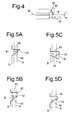
- FIGS 5A-D various configurations of projections 42 of the novel target 40 are shown. Dashed lines A and B indicate the paths along which the observation axis intersects the projections between different axial positions arising from variation in engine operating conditions. It should be appreciated that target features already present in engine components which exhibit these types of profiles may be used.
- the projection 42 comprises an angled side 44 that meets at an apex a side 45 normal to the direction of rotation of the target 40, therefore the width increases from paths A to B.
- the projection 42 comprises an angled side 44 and a side 45 normal to the direction of rotation of the target 40 and which are spaced apart by a width 47.
- the projection 42 comprises a reversely angled side 44 that meets at a width 47 with a side 45 normal to the direction of rotation of the target 40, therefore the width decreases from paths A to B.
- the projection 42 comprises at least one arcuate side 44.
- the curve increases the width of the projection corresponding to a non-linear rotor response.
- the displacement measurement arrangement 38 for measuring the movement of a body 14 will also provide an indication of the rotational speed of the body. In certain applications axial and/or radial speed may also be easily calculated.
Abstract
A displacement measurement arrangement (38) for measuring the movement of a body (14), the arrangement (38) comprising a target (40) located on the body (14) and a probe (36) having an observation axis (37), characterised in that the target (40) comprises at least one projection (42) of varying width (41) relative to the intersection path (A, B) of the observation axis (37) and measurement of the movement of the body (14) is made in more than one direction simultaneously.
Description
- The present invention relates to a displacement measurement arrangement, suitable for measuring clearances in gas turbine engines.
- Currently a widely used method of displacement or clearance measurement uses a measurement of capacitance between a probe and a target where capacitance is inversely proportional to the separation (Capacitance = Area /separation).
Figure 2 shows a typical arrangement ofprobes slotted targets 9 and asignal output 6 has amplitude that is calibrated with separation. Such probes and measurement systems may be obtained from Thermocoax and Fogale Nanotech both of France. - This current type of probe and target is applied to discs, shafts, seals etc of gas turbine engines and requires the installation of two
probes target 9. Difficulty is experienced in installing bothprobes - Therefore it is an object of the present invention to provide a displacement measurement arrangement that reduces the number of probes and is therefore cheaper, requires less design time and requires fewer wires enabling easier and quicker installation.
- In accordance with the present invention a gas turbine engine is provided a displacement measurement arrangement for measuring the movement of a body, the arrangement comprising a target located on the body and a probe having an observation axis, characterised in that the target comprises at least one projection of varying width relative to the intersection path of the observation axis and measurement of the movement of the body is made in more than one direction simultaneously.
- Normally, the body is rotating.
- Alternatively, the target is formed by a configuration of the body.
- Preferably, the target comprises a general two dimensional shape from any one of the group comprising a triangle or trapezoid.
- Alternatively, the target comprises an arcuate side. Preferably, the target comprises an annular array of projections.
- Another aspect of the present invention is provided by a method of measuring the displacement of a body comprising a displacement measurement arrangement as set out in the preceding paragraphs, the method comprises the steps of a) rotating the body at a first speed and rotating the body at a second speed wherein the body displaces in at least one of a radial or axial direction, b) recording the output of the probe as the target passes along the two paths as an amplitude and timing variation, c) calibrating radial movement of the target with the amplitude variation and axial movement of the target with a timing variation; thereby measuring the movement of the body in more than one direction simultaneously.
- The present invention will be more fully described by way of example with reference to the accompanying drawings in which:
-
Figure 1 is a schematic section of part of a ducted fan gas turbine engine; -
Figure 2 is a prior art displacement measurement arrangement including two probes and a target; -
Figure 3 is a displacement measurement arrangement comprising a single probe and novel target in accordance with the present invention; -
Figure 4 is a second embodiment of the displacement measurement arrangement in accordance with the present invention. -
Figures 5A-D show further embodiments of the target in accordance with the present invention. - With reference to
Figure 1 , a ducted fan gas turbine engine generally indicated at 10 has a principal androtational axis 11. Theengine 10 comprises, in axial flow series, anair intake 12, apropulsive fan 13, an intermediate pressure compressor 14, a high-pressure compressor 15,combustion equipment 16, a high-pressure turbine 17, andintermediate pressure turbine 18, a low-pressure turbine 19 and a coreengine exhaust nozzle 20. Anacelle 21 generally surrounds theengine 10 and defines theintake 12, a bypass duct 22 and abypass exhaust nozzle 23. - The
gas turbine engine 10 works in the conventional manner so that air entering theintake 11 is accelerated by thefan 13 to produce two air flows: a first air flow into the intermediate pressure compressor 14 and a second air flow which passes through a bypass duct 22 to provide propulsive thrust. The intermediate pressure compressor 14 compresses the air flow directed into it before delivering that air to thehigh pressure compressor 15 where further compression takes place. - The compressed air exhausted from the high-
pressure compressor 15 is directed into thecombustion equipment 16 where it is mixed with fuel and the mixture combusted. The resultant hot combustion products then expand through, and thereby drive the high, intermediate and low-pressure turbines nozzle 20 to provide additional propulsive thrust. The high, intermediate and low-pressure turbines intermediate pressure compressors 15, 14 and thefan 13 by suitable interconnecting shafts. - Each compressor and turbine has at least one rotor stage that comprises a rotor disc having an annular array of radially extending blades attached in convention fashion thereto. The blades rotate within a casing 24 and it is preferable to have a minimal gap or clearance between the tips of the blades and the casing to prevent over-tip leakage and therefore efficiency loss. During engine operation thermal and mechanical forces affect the tip clearances. To ensure the minimal clearances, it is desirable to know the range of movement a rotor disc and its blades undergo. It is common for casings and rotors to be cooled and scheduling of this cooling can control the thermal movements and therefore the tip clearances.
- Referring now to
Figure 3 , the present invention is adisplacement measuring arrangement 38 embodied by a circular orcylindrical target 40, rotating aboutaxis 30 and havingprojections 42 which vary inwidth 41 in the axial direction. Theprojections 42 provide a discontinuous target, 40 to aprobe 36 that varies geometrically in the axial direction. - The
probe 36 has anobservation axis 37 and is orientated in a radial direction, thetarget 40 being attached to or formed as an integral part of the disc or component to be measured such that it rotates with the disc about thesame axis 30. In use the disc rotates and thetarget 40 travels passed theprobe 36. - Preferably, the
projections 42 are V-shaped teeth and the resulting signal will contain both radial and axial displacement information. Thisdistance measuring arrangement 38 is installed more easily and cheaper than the prior art arrangement due to the requirement to only fit oneprobe 36 and its leads. - A variety of tooth shapes could be used to the same effect, but each must comprise a variable width and as such has at least one
angled side 44. It is important also that theaxial extent 46 of thetarget 40 is larger than the range of movement of the body it is located on (a disc in this example). One preferred example is a compressor disc having atarget 40 defining zigzag likeprojections 42 having an apex angle ø 90°, where bothsides - Radial movement of the disc and therefore
target 40 leads to anoutput having amplitude 51 variation as seen betweenlines probe 36 generating a timing variation as seen betweenlines gap 56 totooth 58 ratio changes. These signal variations with radial and axial displacements are calibrated, therefore allowing radial and axial displacements to be identified. - In
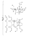
Figure 3 , where thetarget 40 hasprojections 42 which vary inwidth 41 in the axial direction, theprobe 36 is oriented with itslongitudinal axis 37 in the radial direction. An alternative orientation is where the target has projections which vary in width in the radial direction, in which case the probe axis would be situated in the axial direction as shown inFigure 4 . In this configuration, axial movement would produce a variation in signal amplitude as seen inlines lines - The present invention is advantageous because it reduces the number of probes and is therefore cheaper requires less design time and requires fewer wires enabling easier and quicker installation. Furthermore, the present invention allows two dimensional measurements where there is only space for one
probe 36. - The present invention is adaptable to particular applications where the target is located on a body which is subject to greater movement in one direction that another. Here the projection profiles are adjusted by varying the included angle o to adjust relative sensitivity to axial or radial movements. Furthermore, accuracy may be increased in the more critical direction where the axial extent of the projections was increased for example.
- It should be appreciated that the
probe 36 may be any one of the types including capacitance, eddy current, inductive, microwave and optical. - The present invention is applicable to non-contact displacement or position measurement in any rotating or reciprocating machinery, for example other engines in general, electrical motors / generators, optical storage devices such as compact discs or digital video discs, shafts and machine tools.
- In
Figures 5A-D various configurations ofprojections 42 of thenovel target 40 are shown. Dashed lines A and B indicate the paths along which the observation axis intersects the projections between different axial positions arising from variation in engine operating conditions. It should be appreciated that target features already present in engine components which exhibit these types of profiles may be used. - In
Figure 5A , theprojection 42 comprises anangled side 44 that meets at an apex aside 45 normal to the direction of rotation of thetarget 40, therefore the width increases from paths A to B. InFigure 5B , theprojection 42 comprises anangled side 44 and aside 45 normal to the direction of rotation of thetarget 40 and which are spaced apart by awidth 47. - In
Figure 5C , theprojection 42 comprises a reverselyangled side 44 that meets at awidth 47 with aside 45 normal to the direction of rotation of thetarget 40, therefore the width decreases from paths A to B. - In
Figure 5D , theprojection 42 comprises at least onearcuate side 44. Here the curve increases the width of the projection corresponding to a non-linear rotor response. - In
Figures 5A-D is should be appreciated thatside 45 may be angled or arcuate. - It should be appreciated that the
displacement measurement arrangement 38 for measuring the movement of a body 14 will also provide an indication of the rotational speed of the body. In certain applications axial and/or radial speed may also be easily calculated.
Claims (7)
- A displacement measurement arrangement (38) for measuring the movement of a body (14), the arrangement (38) comprising a target (40) located on the body (14) and a probe (36) having an observation axis (37), characterised in that the target (40) comprises at least one projection (42) of varying width (41) relative to the intersection path (A, B) of the observation axis (37) and measurement of the movement of the body (14) is made in more than one direction simultaneously.
- A displacement measurement arrangement (38) as claimed in claim 1 wherein the body (14) is rotating.
- A displacement measurement arrangement (38) as claimed in any one of claims 1-2 wherein the target (40) is formed by a configuration of the body (14).
- A displacement measurement arrangement (38) as claimed in any one of claims 1-3 wherein the target (40) comprises a general two dimensional shape from any one of the group comprising a triangle or trapezoid.
- A displacement measurement arrangement (38) as claimed in any one of claims 1-4 wherein the target (40) comprises an arcuate side.
- A displacement measurement arrangement (38) as claimed in any one of claims 1-5 wherein the target (40) comprises an annular array of projections (42).
- A method of measuring the displacement of a body (14) comprising a displacement measurement arrangement (38) as claimed in claim 1, the method comprises the steps ofa) rotating the body at a first speed and rotating the body at a second speed wherein the body displaces in at least one of a radial or axial direction,b) recording the output of the probe as the target passes along the two paths (A, B) as an amplitude and timing variation,c) calibrating radial movement of the target (40) with the amplitude (48, 50) variation and axial movement of the target with a timing variation (52, 54),
thereby measuring the movement of the body (14) in more than one direction simultaneously.
Applications Claiming Priority (1)
| Application Number | Priority Date | Filing Date | Title |
|---|---|---|---|
| GBGB0713108.9A GB0713108D0 (en) | 2007-07-06 | 2007-07-06 | Displacement measurement arrangement |
Publications (1)
| Publication Number | Publication Date |
|---|---|
| EP2012086A1 true EP2012086A1 (en) | 2009-01-07 |
Family
ID=38440483
Family Applications (1)
| Application Number | Title | Priority Date | Filing Date |
|---|---|---|---|
| EP08251983A Withdrawn EP2012086A1 (en) | 2007-07-06 | 2008-06-06 | Displacement measurement arrangement |
Country Status (2)
| Country | Link |
|---|---|
| EP (1) | EP2012086A1 (en) |
| GB (1) | GB0713108D0 (en) |
Cited By (5)
| Publication number | Priority date | Publication date | Assignee | Title |
|---|---|---|---|---|
| GB2465575A (en) * | 2008-11-21 | 2010-05-26 | Rolls Royce Plc | Displacement measurement / rotor blade pitch measurement arrangement |
| EP3671106A1 (en) * | 2018-12-20 | 2020-06-24 | Rolls-Royce plc | Shaft monitoring system |
| EP3674654A1 (en) * | 2018-12-20 | 2020-07-01 | Rolls-Royce Deutschland Ltd & Co KG | Shaft monitoring system |
| EP4040101A1 (en) * | 2018-06-19 | 2022-08-10 | Raytheon Technologies Corporation | Systems and methods for pseudo-triaxial capacitance probe assemblies |
| EP4152009A1 (en) * | 2021-09-20 | 2023-03-22 | TE Connectivity Germany GmbH | Sensor and method to measure the speed and axial displacement of a rotating target and to control a continuously variable transmission |
Citations (6)
| Publication number | Priority date | Publication date | Assignee | Title |
|---|---|---|---|---|
| US3488581A (en) * | 1967-10-03 | 1970-01-06 | Reliance Electric & Eng Co | Surface interruption calibrated non-contact transducer system |
| GB2062875A (en) * | 1979-11-03 | 1981-05-28 | Lucas Industries Ltd | Rotation and axial displacement transducers |
| US4820980A (en) * | 1987-05-04 | 1989-04-11 | Dodson Edgars Darryl | Gap, wear and tram measurement system and method for grinding machines |
| EP0334441A1 (en) * | 1988-03-25 | 1989-09-27 | Thermocoax | Capacitive transducer |
| EP0443514A2 (en) * | 1990-02-20 | 1991-08-28 | Nikkiso Co., Ltd. | Apparatus for monitoring a bearing |
| US5469055A (en) * | 1994-05-04 | 1995-11-21 | Honeywell Inc. | Engine shaft with integrally formed complementary targets |
-
2007
- 2007-07-06 GB GBGB0713108.9A patent/GB0713108D0/en not_active Ceased
-
2008
- 2008-06-06 EP EP08251983A patent/EP2012086A1/en not_active Withdrawn
Patent Citations (6)
| Publication number | Priority date | Publication date | Assignee | Title |
|---|---|---|---|---|
| US3488581A (en) * | 1967-10-03 | 1970-01-06 | Reliance Electric & Eng Co | Surface interruption calibrated non-contact transducer system |
| GB2062875A (en) * | 1979-11-03 | 1981-05-28 | Lucas Industries Ltd | Rotation and axial displacement transducers |
| US4820980A (en) * | 1987-05-04 | 1989-04-11 | Dodson Edgars Darryl | Gap, wear and tram measurement system and method for grinding machines |
| EP0334441A1 (en) * | 1988-03-25 | 1989-09-27 | Thermocoax | Capacitive transducer |
| EP0443514A2 (en) * | 1990-02-20 | 1991-08-28 | Nikkiso Co., Ltd. | Apparatus for monitoring a bearing |
| US5469055A (en) * | 1994-05-04 | 1995-11-21 | Honeywell Inc. | Engine shaft with integrally formed complementary targets |
Cited By (6)
| Publication number | Priority date | Publication date | Assignee | Title |
|---|---|---|---|---|
| GB2465575A (en) * | 2008-11-21 | 2010-05-26 | Rolls Royce Plc | Displacement measurement / rotor blade pitch measurement arrangement |
| EP4040101A1 (en) * | 2018-06-19 | 2022-08-10 | Raytheon Technologies Corporation | Systems and methods for pseudo-triaxial capacitance probe assemblies |
| EP3671106A1 (en) * | 2018-12-20 | 2020-06-24 | Rolls-Royce plc | Shaft monitoring system |
| EP3674654A1 (en) * | 2018-12-20 | 2020-07-01 | Rolls-Royce Deutschland Ltd & Co KG | Shaft monitoring system |
| US11561235B2 (en) | 2018-12-20 | 2023-01-24 | Rolls-Royce Plc | Shaft monitoring system |
| EP4152009A1 (en) * | 2021-09-20 | 2023-03-22 | TE Connectivity Germany GmbH | Sensor and method to measure the speed and axial displacement of a rotating target and to control a continuously variable transmission |
Also Published As
| Publication number | Publication date |
|---|---|
| GB0713108D0 (en) | 2007-08-15 |
Similar Documents
| Publication | Publication Date | Title |
|---|---|---|
| US7688081B2 (en) | Apparatus to measure the clearance between a first component and a second component | |
| CN102252642B (en) | Relevant method is calculated to the tip clearance in turbine engine | |
| US7341426B2 (en) | Gas turbine engine blade tip clearance apparatus and method | |
| EP1795861B1 (en) | Multi-range clearance measurement system and method of operation | |
| EP2591238B1 (en) | Axial displacement and rotational speed monitoring | |
| EP2012086A1 (en) | Displacement measurement arrangement | |
| US11156119B2 (en) | Relative position measurement | |
| US10126208B2 (en) | Sensor system having a sensor supported by a mast for use within fluid flows | |
| EP3712057A1 (en) | Blade angle position feedback system with extended markers | |
| EP3686606B1 (en) | Shaft monitoring system | |
| EP3766776A1 (en) | Blade angle position feedback system with magnetic shield | |
| EP3744951A1 (en) | Proximity vane angle measurement | |
| Chana et al. | The development of a hot section eddy current sensor for turbine tip clearance measurement | |
| CN107923257A (en) | Drive ring offset sensing system, compressor and gas turbine | |
| EP2574734B1 (en) | Systems and methods for mode shape identification | |
| JP2016524080A (en) | Turbine and friction detection method | |
| EP4303406A1 (en) | System and method for determining rotor whirl displacement | |
| Gill et al. | Turbine tip clearance measurement system evaluation on an industrial gas turbine | |
| Batman | Design and Development of a Family of Natural Gas Compressors for a 3000-Hp Gas Turbine Engine |
Legal Events
| Date | Code | Title | Description |
|---|---|---|---|
| PUAI | Public reference made under article 153(3) epc to a published international application that has entered the european phase |
Free format text: ORIGINAL CODE: 0009012 |
|
| AK | Designated contracting states |
Kind code of ref document: A1 Designated state(s): AT BE BG CH CY CZ DE DK EE ES FI FR GB GR HR HU IE IS IT LI LT LU LV MC MT NL NO PL PT RO SE SI SK TR |
|
| AX | Request for extension of the european patent |
Extension state: AL BA MK RS |
|
| AKX | Designation fees paid |
Designated state(s): DE FR GB |
|
| STAA | Information on the status of an ep patent application or granted ep patent |
Free format text: STATUS: THE APPLICATION IS DEEMED TO BE WITHDRAWN |
|
| 18D | Application deemed to be withdrawn |
Effective date: 20090708 |