CN103306753A - Cooling water system for turboset and cooling water supplying method - Google Patents
Cooling water system for turboset and cooling water supplying method Download PDFInfo
- Publication number
- CN103306753A CN103306753A CN201310208998XA CN201310208998A CN103306753A CN 103306753 A CN103306753 A CN 103306753A CN 201310208998X A CN201310208998X A CN 201310208998XA CN 201310208998 A CN201310208998 A CN 201310208998A CN 103306753 A CN103306753 A CN 103306753A
- Authority
- CN
- China
- Prior art keywords
- water
- steam turbine
- power generation
- generation unit
- turbine power
- Prior art date
- Legal status (The legal status is an assumption and is not a legal conclusion. Google has not performed a legal analysis and makes no representation as to the accuracy of the status listed.)
- Granted
Links
Classifications
-
- Y—GENERAL TAGGING OF NEW TECHNOLOGICAL DEVELOPMENTS; GENERAL TAGGING OF CROSS-SECTIONAL TECHNOLOGIES SPANNING OVER SEVERAL SECTIONS OF THE IPC; TECHNICAL SUBJECTS COVERED BY FORMER USPC CROSS-REFERENCE ART COLLECTIONS [XRACs] AND DIGESTS
- Y02—TECHNOLOGIES OR APPLICATIONS FOR MITIGATION OR ADAPTATION AGAINST CLIMATE CHANGE
- Y02E—REDUCTION OF GREENHOUSE GAS [GHG] EMISSIONS, RELATED TO ENERGY GENERATION, TRANSMISSION OR DISTRIBUTION
- Y02E20/00—Combustion technologies with mitigation potential
- Y02E20/14—Combined heat and power generation [CHP]
Landscapes
- Turbine Rotor Nozzle Sealing (AREA)
- Engine Equipment That Uses Special Cycles (AREA)
- Control Of Turbines (AREA)
Abstract
The invention provides a cooling water system for a turboset, which includes a first turbine generator set and a second turbine generator set, wherein cooling equipment is arranged inside the second turbine generator set; and the cooling water system further includes a second turbine generator set water reuse system, a second turbine generator set forebay, and a second turbine generator set machine room. The cooling water system adopting the first turbine generator set and the second turbine generator set provides two paths of water sources to cool the cooling equipment, enables the two paths of water sources to be alternatively used during heat supply, solves the problems that the cooling equipment cannot be cooled completely and the loss of a cold source is huge in a big generator set for generation in case of winter heat supply, maintains the operation efficiency in summer for generation at the same time, and has the characteristics of simple structure, reasonable design, convenience for mounting and operation, low construction cost, remarkable energy-saving effect and the like.
Description
Technical field
The present invention relates to a kind of cooling water system, relate to particularly a kind of steam turbine set cooling water system, the invention still further relates to a kind of Supply Method, relate to particularly a kind of chilled(cooling) water supply (CWS) method.
Background technique
Along with improving constantly of living standards of the people, area of heat-supply service is constantly developed, and heating load constantly increases, and as the heat supply work of one of government's " people's livelihood " engineering, relates to huge numbers of families' quality of life, is day by day paid attention to.Become the good exploration that ensures reliability of heat-supply system so develop new heat supply process, have important social effect.At present China's heat supply present situation is take extraction for heat supply and little unit rough vacuum back pressure heat supply process as main, and the minority region has and utilizes earth source heat pump to implement for the cold-peace heat supply.Because the continuous expansion of area of heat-supply service and Plant reconstruction plant modernization lag behind, and the boiler heat supplying mode that occupies a narrow space still exists, this heat-supplying mode not only environmental pollution is serious, and the Economy extreme difference in addition.
The heat supply of large-scale unit back pressure is current better heat-supplying mode, but the unit of operation only has an example in this way, and just rest in the disposable transformation that low pressure rotor and corresponding dividing plate carry out, cause non-heat supply phase Economy extreme difference, make annual economic benefit unsatisfactory.Extraction for heat supply is to use at present maximum heat-supplying modes, and utilization ratio is hanged down and the larger phenomenon of cold source energy but its existence is drawn gas.Although little unit rough vacuum back pressure heat supply process cold source energy is zero, but because little unit operation parameter is lower, generation load and boiler caloric receptivity ratio are less, limited generation load, economic benefit is still undesirable, because little unit heat capacity is limited, can't satisfy extensive heat demand simultaneously.
For this reason, seek that a kind of cold source energy is minimum, generation load and the boiler ratio heat supply mode higher, that satisfy extensive heat demand simultaneously that recepts the caloric is the task of top priority.Prove according to theory and practice, the back pressure heat supply of large unit high parameter can achieve the above object.But, in large unit heating system, steam turbine set inside arranges the in time equipment of cooling of a large amount of needs, such as air cooling device, generator etc., traditional type of cooling is often because the cooling water flow of single large unit is inadequate or pressure is inadequate, for example in Chinese patent CN1916506A, provide a kind of single; Chilled(cooling) water supply (CWS) system and method for supplying, this single cooling water system can not cool off fully to cooling equipments numerous in the large unit, thereby causes these device operations overheated and accidents caused.
Summary of the invention
In order to solve the problems of the technologies described above, the invention provides a kind of steam turbine set cooling water system, it comprises the first steam turbine power generation unit and the second steam turbine power generation unit, in the second steam turbine power generation unit, be provided with cooling equipment, wherein the female pipe of the first steam turbine power generation unit and the first circulating water water inlet and the second circulating water female pipe of intaking is connected, the female pipe of the first circulating water water inlet and the female pipe of the second circulating water water inlet extend respectively the first branch road and the second branch road, the first branch road and the second branch road merge into cooling water and replenish branch road, this cooling water system also comprises the second steam turbine power generation unit circulation, the second steam turbine power generation unit forebay and the second steam turbine power generation unit machine room, between the second steam turbine power generation unit and the second steam turbine power generation unit forebay, be connected with the female pipe of the 3rd circulating water water inlet, between the second steam turbine power generation unit forebay and the second steam turbine power generation unit machine room, be connected with the first main water inlet tube and the second main water inlet tube, be provided with cooling waterpump and the 3rd gate valve at the first main water inlet tube, wherein be disposed with one-way valve at the second main water inlet tube, circulating water pump and the 4th gate valve, cooling water replenishes branch road and converges mutually with the first main water inlet tube, point is between cooling waterpump on the first main water inlet tube and the 3rd gate valve, the second steam turbine power generation unit machine room also is connected with return pipe, and this return pipe is connected to cooling column.
Preferably, the intake the other end of female pipe of the female pipe of the first circulating water water inlet and the second circulating water is connected to the first steam turbine power generation unit circulation by the first steam turbine power generation unit forebay jointly.
Preferably, be respectively arranged with the first gate valve and the second gate valve at the first branch road and the second branch road.
Preferably, cooling waterpump is near the second steam turbine power generation unit machine room one side, and wherein one-way valve is near the second steam turbine power generation unit machine room one side.
Preferably, this cooling equipment comprises air cooler of generators, oil cooler, cooling water machine, feed water pump oil cooler and water supply pump motor air cooling device.
The present invention also provides a kind of above-mentioned each steam turbine set chilled(cooling) water supply (CWS) method of cooling water system that adopts, can adopt the two-way water source to be used alternatingly during the phase in heat supply, thereby the cooling equipment in the second steam turbine power generation unit machine room is cooled off, wherein one the tunnel is to open when the first gate valve and the second gate valve, when the 3rd gate valve and the 4th gate valve are closed, circulating water from the first steam turbine power generation unit circulation, this circulating water is managed by the first circulating water water inlet mother respectively and the second circulating water is intake, and female pipe enters into the first branch road and the second branch road, then converge and enter the additional branch road of cooling water, then entering the supercooling water pump of going forward side by side in the first main water inlet tube boosts, the final second steam turbine power generation unit machine room that arrives, drain into cooling column by return pipe at last, drain back to the first steam turbine power generation unit forebay by diversion gate; Another road be when the first gate valve and the second gate valve is closed and, the 3rd gate valve is opened, when the 4th gate valve is closed, enter the second steam turbine power generation unit forebay from the cooling water of the second steam turbine power generation unit circulation through the 3rd circulating water female pipe of intaking, then boost by the first main water inlet tube and through cooling waterpump and arrive the second steam turbine power generation unit machine room, the abundant cooled water of cooling equipment was advanced return pipe drained into cooling column, drained in the water reservoir by the circulation waste pipe below the cooling column;
In non-heat supply during the phase, the first gate valve, the second gate valve and the 3rd gate valve are closed, the 4th gate valve is opened, enter the second steam turbine power generation unit forebay from the cooling water of the second steam turbine power generation unit circulation through the 3rd circulating water female pipe of intaking, then enter into the second steam turbine power generation unit machine room by the second main water inlet tube through circulating water pump and one-way valve, cooled water drains into cooling column through return pipe.
The present invention also provides a kind of heat supply running method, it carries out heat supply by the heating system that comprises above-mentioned each cooling water system, this heating system is carried out heat supply by the first steam turbine power generation unit and the second steam turbine power generation unit, and concrete heat supply running method is:
(1) normally moves take the second steam turbine power generation unit heat supply heating system as basic mode, add small turbine operation, add the first steam turbine power generation unit heat supply and draw gas and be supplementary heating;
When (2) second steam turbine power generation units are shut down, with the first steam turbine power generation unit heat supply heating circulation water for heating operation of drawing gas, excise the operation of the second steam turbine power generation unit heat supply heater, open the second steam turbine power generation unit machine heat supply heater by-pass power door operation, the circulation water for heating by-passing, according to circumstances excise the second steam turbine power generation station unit condenser operation, open heat supply vapour condenser bypass power door operation, the circulation water for heating by-passing;
(3) the first steam turbine power generation unit heat supplies interruption of drawing gas is opened for hot heater water side bypass power door operation, and excision first, second is for the hot heater operation, and excision first, second small turbine and first, second small turbine are for the hot heater operation;
(4) second steam turbine power generation unit heat supply heaters have a fault need excise operation, should according to the second steam turbine power generation unit heat supply heater circulation water for heating inlet/outlet pressure reduction, open the second steam turbine power generation unit heat supply heater by-pass power door operation and be adjusted at suitable aperture.
Preferably, before using the heat supply small turbine, test in the following way:
(1) check that each table of small turbine counts whole verification qualified, each point position is correct, and controller, electronic actuators, tachometer send electricity, the bearing seat oil tank oil level meets the requirements, open the lubricant oil cooler cock, cooling water is unimpeded, and small turbine heater water side drops into normal;
(2) check that each parts of small turbine are perfect, the moving element flexible movements, without the bite phenomenon, jiggering is light, and the clamping bolt non-loosening is closed pump inlet/outlet door;
(3) hand is clapped the dropout pinch bar on the emergency trip connecting rod, repeats once, uses telecontrol again, presses and makes the lock button, and its hook and flexible movements are tested in action twice;
(4) open steam discharge door and all draining valves, open the steam supply power door operation, hydrophobic 20 minutes of heating coil, and check that initial steam pressure, temperature should meet the requirements, heating coil is hydrophobic complete, the draining valve of blinding off a line;
(5) controller is in the rotating speed state, and manual/auto button is in manual state, predetermined current 4MA, and main stop valve is in full-shut position, and the emergency trip connecting rod is in trip status;
(6) clockwise rotate the main inlet throttle-stop valve handwheel, until the rotating shaft of steam valve assembly move hang up hook after, check that the emergency trip connecting rod is in tensioning state;
(7) rotate counterclockwise the main inlet throttle-stop valve handwheel main inlet throttle-stop valve is opened gradually, open simultaneously packing, after the rotor impulsion, maintain 500-600r/min and carry out warming-up, approximately close draining valve after 30 minutes;
(8) confirm that small turbine is normal after, with 300r/min speed raising speed to 1200r/min;
(9) standard-sized sheet main inlet throttle-stop valve, press the basis weight controller raising speed and observe normal follow-up speed of continuing rising to rated speed 1650r/min to rated speed 1500r/min., emergency governor, overspeed governor should move, as be failure to actuate, rotating speed rises to 1700r/min and answers manual shut-down, adjusts, until pass the test, after for the first time trip test is qualified, carry out again 1-2 retrial;
(10) the small turbine overspeed test is qualified, and the contact thermal control is done the low 0.3MPa of initial steam pressure and the high 0.6MPa warning of exhaust steam pressure test with pressure short circuit method respectively, and pass the test according to circumstances drops into the small turbine operation or stops the small turbine operation, performs record.
Preferably, the investing method of the first steam turbine power generation station unit condenser water side is as follows:
(1) second steam turbine power generation unit vapour condenser circulation water for heating bypass door is in the enable possition, circulation water for heating water supplying pump pressure stability;
(2) close the second steam turbine power generation unit condenser water and be sidelong water valve, open the second steam turbine power generation unit condenser water and be sidelong air gate;
(3) crack the second steam turbine power generation unit vapour condenser circulation water for heating first, second both sides access doors is carried out water-filling; After being sidelong the air gate water breakthrough, the second steam turbine power generation unit condenser water closes;
(4) door is imported and exported in standard-sized sheet the second steam turbine power generation unit vapour condenser circulation water for heating first, second both sides, closes the second steam turbine power generation unit vapour condenser circulation water for heating bypass door; The second steam turbine power generation unit condenser water side puts into operation.
Preferably, the use step of hot heater is as follows:
(1) heater water side bypass door was opened in advance before the circulation water for heating pump was opened, and circulating water is imported and exported door and kept closing; When circulation water for heating water supplying pump pressure stability, heater water is sidelong air, slowly opens out water valve, and water is sidelong and is closed after air gate emits water, and heater circulating water intake door is closed bypass door;
(2) close attention is not more than 0.2 MPa for hot heater water inlet and outlet pressure reduction;
(3) as dropping into two for hot heater, two heater water inlet and outlet pressure divergences must not be greater than 0.2 MPa;
(4) behind the water side normal operation, the report value is long, requires heat supply unit steam supply, after the long heating coil order of the value of receiving, opens steam main draining valve on the way, and steam extraction head begins heating coil;
(5) after steam main is fully hydrophobic, again the heat supply heater system is checked comprehensively, confirm for hot heater water side normal operation;
(6) open heat supply heater condensate bypass door, open the Condensate recovery device sewage door, open for hot heater vapour and be sidelong air gate, open the admission power door operation, open for the hot heater water of condensation and adjust the forward and backward isolating door of door, the crack hot heater water of condensation that supplies is adjusted door; After seeing vapour, heater vapour side air gate closes;
(7) vapor (steam) temperature turns down gradually until close the heat supply pipeline draining valve, contact heat supply unit adjustment extraction for heat supply fast valve more than 120 ℃;
(8) slowly open for the hot heater admission and adjust door, controlled circulation water temperature lifting speed must not be greater than 5 ℃/h, and drops into automatically according to situations such as water temperatures;
(9) according to heat supply heater water level and Condensate recovery device water level situation, after water quality is slightly good, when namely free from admixture and color are more clear, open water of condensation recycle-water pipeline draining valve on the way;
(10) after chemical examination water quality was qualified, the report value was long, and after the value of the receiving long life order, the contact squad leader drops into the operation of heat supply tramp iron separator, opens the water of condensation recycle-water to oxygen-eliminating device hand operated door and pitch;
(11) open the Condensate recovery device outlet portal, heat supply condensate pump access doors, variable frequency starting heat supply condensate pump is opened outlet portal, drops into the operation of heat supply condensate pump;
(12) the heat supply coagulation hydroenergy backwater is finished to the oxygen-eliminating device condensing water conduit is hydrophobic, closes draining valve, regulates heat supply Condensate Pump Frequency Conversion device, makes heat supply condensate pump outlet pressure reach 1.0MPa;
(13) check each circulation water for heating pump, heat supply condensate pump, Condensate recovery device normal operation, each power door operation, safety valve, pressure gauge, thermometer are all normal, and protection and interlocking drop into normal, and long, the relevant leader of report value is for the hot heater normal operation.
The cooling water system that employing the present invention relates to and chilled(cooling) water supply (CWS) method, the problem that cooling equipment when solving the Winter heat supply generating in the large unit can not be sufficiently cooled and cold source energy is larger, kept simultaneously the efficient of summer during generator operation, have simple in structure, reasonable in design, the characteristics such as fitting operation is convenient, and cost is low, and energy-saving effect is remarkable.It is lower that the heat supply running method that the present invention relates to has solved in the past little unit heating system Operational Limits, generation load and boiler caloric receptivity ratio are less, generation load is limited, the problem that economic benefit is undesirable, also solved simultaneously because little unit heat capacity is limited, can't satisfy the present situation of extensive heat demand.
Description of drawings
Fig. 1 be according to the present invention in the steam turbine set of an exemplary embodiment with the schematic diagram of cooling water system.
Embodiment
A detailed exemplary embodiment is described among the 1 couple of the present invention below with reference to the accompanying drawings.
Fig. 1 shows a kind of cooling water system, it comprises the first steam turbine power generation unit 1 and the second steam turbine power generation unit 2, in the second steam turbine power generation unit 2, be provided with cooling equipment 3, this cooling equipment 3 comprises air cooler of generators, oil cooler, cooling water machine, feed water pump oil cooler and water supply pump motor air cooling device, wherein the first steam turbine power generation unit 1 is connected with the female pipe 6 of the second circulating water water inlet with the female pipe 5 of the first circulating water water inlet, wherein, the other end of the female pipe 6 of the female pipe of the first circulating water water inlet the 5 and second circulating water water inlet is connected to the first steam turbine power generation unit circulation 8 by the first steam turbine power generation unit forebay 7 jointly, the female pipe 6 of the female pipe of the first circulating water water inlet the 5 and second circulating water water inlet extends respectively the first branch road 9 and the second branch road 10, be respectively arranged with the first gate valve 11 and the second gate valve 12 at the first branch road 9 and the second branch road 10, the first branch road 9 and the second branch road 10 merge into cooling water and replenish branch road 13, this cooling water system also comprises the second steam turbine power generation unit circulation 14, the second steam turbine power generation unit forebay 15 and the second steam turbine power generation unit machine room, the second steam turbine power generation unit 2 is positioned at machine room, between the second steam turbine power generation unit circulation 14 and the second steam turbine power generation unit forebay 15, be connected with the female pipe 16 of the 3rd circulating water water inlet, between the second steam turbine power generation unit forebay 15 and the second steam turbine power generation unit machine room, be connected with the first main water inlet tube 17 and the second main water inlet tube 18, be provided with cooling waterpump 19 and the 3rd gate valve 20 at the first main water inlet tube 17, wherein, cooling waterpump 19 is near the second steam turbine power generation unit machine room one side, be disposed with one-way valve 21 at the second main water inlet tube 18, circulating water pump 22 and the 4th gate valve 23, wherein one-way valve 21 is near the second steam turbine power generation unit machine room one side, cooling water replenishes branch road 13 and converges mutually with the first main water inlet tube 17, point is between cooling waterpump 19 on the first main water inlet tube 17 and the 3rd gate valve 20, the second steam turbine power generation unit machine room also is connected with return pipe 24, and this return pipe 24 is connected to cooling column 25.
Like this, can adopt the two-way water source to be used alternatingly during the phase in heat supply, thereby the cooling equipment 3 in the second steam turbine power generation unit machine room is cooled off, wherein one the tunnel is to open when the first gate valve 11 and the second gate valve 12, when the 3rd gate valve 20 and the 4th gate valve 23 are closed, circulating water from the first steam turbine power generation unit circulation 8, this circulating water enters into the first branch road 11 and the second branch road 12 by the female pipe 6 of the female pipe of the first circulating water water inlet the 5 and second circulating water water inlet respectively, then converge and enter the additional branch road 13 of cooling water, then entering the supercooling water pump 19 of going forward side by side in the first main water inlet tube 17 boosts, the final second steam turbine power generation unit machine room that arrives, drain into cooling column 25 by return pipe 24 at last, drain back to the first steam turbine power generation unit forebay 7 by diversion gate; Another road be when the first gate valve 11 and the second gate valve 12 is closed and, the 3rd gate valve 20 is opened, when the 4th gate valve 23 is closed, cooling water from the second steam turbine power generation unit circulation 14 enters the second steam turbine power generation unit forebay 15 through the female pipe 16 of the 3rd circulating water water inlet, then boost by the first main water inlet tube 17 and through cooling waterpump 19 and arrive the second steam turbine power generation unit machine room, cooling equipment 3 abundant cooled water were advanced return pipe 24 drain into cooling column 25, the circulation waste pipe by cooling column 25 belows drains in the water reservoir.
In non-heat supply during the phase, the first gate valve 11, the second gate valve 12 and the 3rd gate valve 20 are closed, the 4th gate valve 23 is opened, cooling water from the second steam turbine power generation unit circulation 14 enters the second steam turbine power generation unit forebay 15 through the female pipe 16 of the 3rd circulating water water inlet, then enter into the second steam turbine power generation unit machine room by the second main water inlet tube 18 through circulating water pump 22 and one-way valve 21, cooled water drains into cooling column 25 through return pipe 24.
Above forebay refers to that circulating water is gathered together first before entering steam turbine set, be used for adjust flux water reservoir.
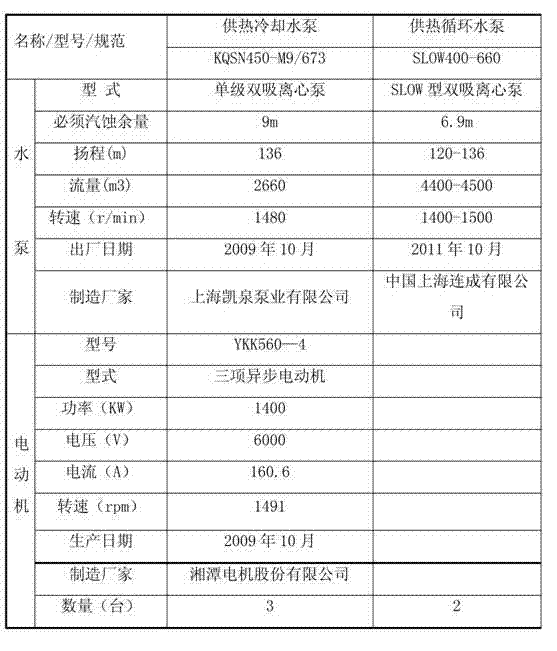
As shown in table 1 below, cooling waterpump wherein and circulating water pump adopt following technical parameter:
Wherein, can adopt following methods for the operation of circulation water for heating pump:
1, after supervisor's net is filled with water, close the second steam turbine power generation unit vapour condenser circulation water for heating first, second both sides and import and export door, open the second steam turbine power generation unit vapour condenser circulation water for heating bypass door.Close each for hot heater water-in and water-out door, open for hot heater circulating-water bypass road door.Open circulation water for heating pump inlet door, open for the hot recycle pump door of dropping a hint, the pump housing drops a hint and cuts out after the water outlet, starts the circulation water for heating pump.Open circulation water for heating pump discharge power door operation, drop into frequency conversion, frequency variator manually is set, according to circumstances slow raising speed.Check that comprehensively each parts of circulation water for heating pump are good.
2, increase gradually circulating water pump and exert oneself, when frequency converter frequency near power frequency, supervisor's net flow does not still reach requirement, should start other circulation water for heating pump, to increase supervisor's net flow.Regulate first frequency conversion circulating water pump and arrange, keep water main pipe pressure to be no more than 1.5MPa.
3, according to the pressure condition of confession, water return pipeline, report squad leader, value length.
4, circulating water pump protection interlocking should place " input " position.
The present invention is concrete to use by adopting above-mentioned cooling water system, is carrying out heat supply by the first steam turbine power generation unit and the second steam turbine power generation unit, and concrete heat supply running mode is:
1, normally moves take the second steam turbine power generation unit heat supply heating system as basic mode, add small turbine operation, add the first steam turbine power generation unit heat supply and draw gas and be supplementary heating.
When 2, the second steam turbine power generation unit is shut down, with the first steam turbine power generation unit heat supply heating circulation water for heating operation of drawing gas.Excise the operation of the second steam turbine power generation unit heat supply heater, open the second steam turbine power generation unit machine heat supply heater by-pass power door operation, the circulation water for heating by-passing.According to circumstances excise the second steam turbine power generation station unit condenser operation in good time, open heat supply vapour condenser bypass power door operation, the circulation water for heating by-passing.
3, the first steam turbine power generation unit heat supply interruption of drawing gas is opened for hot heater water side bypass power door operation, and excision first, second is for the hot heater operation, and the little machine of the excision little machine of first, second and first, second is for the hot heater operation.
4, the second steam turbine power generation unit heat supply heater has a fault need excise operation, should according to the second steam turbine power generation unit heat supply heater circulation water for heating inlet/outlet pressure reduction, open the second steam turbine power generation unit heat supply heater by-pass power door operation and be adjusted at suitable aperture.
Mainly detect data such as table 2 at run duration:
Table 2 main monitoring data in service
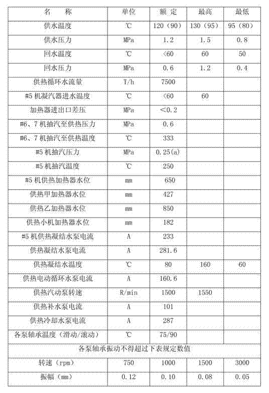
The heating equipment Operational Limits is as shown in table 3, table 3 heating equipment Operational Limits
The Operational Limits of wherein said small turbine is as shown in table 4:
Table 4 small turbine standard
Before using the heat supply small turbine, test in the following way:
1, check that each table of little machine counts whole verification qualified, each point position is correct.Controller, electronic actuators, tachometer send electricity.The bearing seat oil tank oil level meets the requirements.Open the lubricant oil cooler cock, cooling water is unimpeded.Little machine heater water side drops into normal.
2, check that each parts of little machine are perfect, the moving element flexible movements are without the bite phenomenon.Jiggering is light, the clamping bolt non-loosening.Close pump inlet/outlet door.
3, hand is clapped the dropout pinch bar on the emergency trip connecting rod, repeats once.Use telecontrol again, press and make the lock button, its hook and flexible movements are tested in action twice.
4, open steam discharge door and all draining valves.Open the steam supply power door operation, hydrophobic 20 minutes of heating coil, and check that initial steam pressure, temperature should meet the requirements.Heating coil is hydrophobic complete, the draining valve of blinding off a line.
5, controller is in the rotating speed state, and manual/auto button is in manual state, predetermined current 4MA, and main stop valve is in full-shut position, and the emergency trip connecting rod is in trip status.
6, clockwise rotate the main inlet throttle-stop valve handwheel, until the rotating shaft of steam valve assembly move hang up hook after, check that the emergency trip connecting rod is in tensioning state.
7, rotate counterclockwise the main inlet throttle-stop valve handwheel main inlet throttle-stop valve is opened gradually, open simultaneously packing.After the rotor impulsion, maintain 500-600r/min and carry out warming-up, approximately close draining valve after 30 minutes.
8, confirm that little machine is normal after, with 300r/min speed raising speed to 1200r/min.
9, standard-sized sheet main inlet throttle-stop valve is pressed the basis weight controller raising speed and is observed normal follow-up speed of continuing rising to rated speed 1650r/min to rated speed 1500r/min., and emergency governor, overspeed governor should move.As be failure to actuate, rotating speed rises to 1700r/min and answers manual shut-down.Adjust, until pass the test.After for the first time trip test is qualified, carry out again 1-2 retrial.
10, little machine overspeed test is qualified, and the contact thermal control is done the low 0.3MPa of initial steam pressure and the high 0.6MPa warning of exhaust steam pressure test with pressure short circuit method respectively.Pass the test according to circumstances drops into little machine operation or stops little machine operation, performs record.
The investing method of the first steam turbine power generation station unit condenser water side is as follows:
1, the second steam turbine power generation unit vapour condenser circulation water for heating bypass door is in the enable possition, circulation water for heating water supplying pump pressure stability.
2, close the second steam turbine power generation unit condenser water and be sidelong water valve, open the second steam turbine power generation unit condenser water and be sidelong air gate.
3, crack the second steam turbine power generation unit vapour condenser circulation water for heating first, second both sides access doors is carried out water-filling; After being sidelong the air gate water breakthrough, the second steam turbine power generation unit condenser water closes.
4, door is imported and exported in standard-sized sheet the second steam turbine power generation unit vapour condenser circulation water for heating first, second both sides, closes the second steam turbine power generation unit vapour condenser circulation water for heating bypass door; The second steam turbine power generation unit condenser water side puts into operation.
Use as follows for the step of hot heater:
1, heater water side bypass door was opened in advance before the circulation water for heating pump was opened, and circulating water is imported and exported door and kept closing; When circulation water for heating water supplying pump pressure stability, heater water is sidelong air, slowly opens out water valve, and water is sidelong and is closed after air gate emits water, and heater circulating water intake door is closed bypass door.
2, close attention is not more than 0.2 MPa for hot heater water inlet and outlet pressure reduction.
3, as dropping into two for hot heater, two heater water inlet and outlet pressure divergences must not be greater than 0.2 MPa.
4, behind the water side normal operation, the report value is long.Require heat supply unit steam supply.After the long heating coil order of the value of receiving, open steam main draining valve on the way, steam extraction head begins heating coil.
5, after steam main is fully hydrophobic, again the heat supply heater system is checked comprehensively, confirm for hot heater water side normal operation.
6, open heat supply heater condensate bypass door, open the Condensate recovery device sewage door, open for hot heater vapour and be sidelong air gate, open the admission power door operation, open for the hot heater water of condensation and adjust the forward and backward isolating door of door, the crack hot heater water of condensation that supplies is adjusted door; After seeing vapour, heater vapour side air gate closes.
7, vapor (steam) temperature turns down gradually until close the heat supply pipeline draining valve, contact heat supply unit adjustment extraction for heat supply fast valve more than 120 ℃.
8, slowly open for the hot heater admission and adjust door, controlled circulation water temperature lifting speed must not be greater than 5 ℃/h, and drops into automatically according to situations such as water temperatures.
9, according to heat supply heater water level and Condensate recovery device water level situation, (initial start-up after putting into operation for the first time or stopping transport for a long time will be carried out the blowdown flushing) water quality slightly good rear (when free from admixture and color are more clear) is opened water of condensation recycle-water pipeline draining valve on the way.
10, after chemical examination water quality was qualified, the report value was long.After the value of the receiving long life order, the contact squad leader drops into the operation of heat supply tramp iron separator, opens the water of condensation recycle-water to oxygen-eliminating device hand operated door and pitch.
11, open the Condensate recovery device outlet portal, heat supply condensate pump access doors, variable frequency starting heat supply condensate pump is opened outlet portal, drops into the operation of heat supply condensate pump.
12, the heat supply coagulation hydroenergy backwater is finished to the oxygen-eliminating device condensing water conduit is hydrophobic, closes draining valve, regulates heat supply Condensate Pump Frequency Conversion device, makes heat supply condensate pump outlet pressure reach 1.0MPa.
13, check each circulation water for heating pump, heat supply condensate pump, Condensate recovery device normal operation, each power door operation, safety valve, pressure gauge, thermometer are all normal, and protection and interlocking drop into normal, and long, the relevant leader of report value is for the hot heater normal operation.
An exemplary embodiment of the present invention has obtained detailed description with reference to accompanying drawing.These detailed descriptions further believe content only for those skilled in the art, being used for implementing preferred aspect of the present invention, and can not limit scope of the present invention.Only have the right requirement for determining protection scope of the present invention.Therefore, the feature in aforementioned detailed description and step in conjunction with dispensable in the broadest scope, implementing the present invention, and replacedly only the exemplary embodiment of special detailed description of the present invention is provided instruction.In addition, use embodiment in order to obtain of the present invention being attached with, in specification, provide the in several ways combination of various feature of instruction, yet these modes are not exemplified out especially.
Claims (10)
1. steam turbine set cooling water system, it comprises the first steam turbine power generation unit and the second steam turbine power generation unit, in the second steam turbine power generation unit, be provided with cooling equipment, wherein the female pipe of the first steam turbine power generation unit and the first circulating water water inlet and the second circulating water female pipe of intaking is connected, the female pipe of the first circulating water water inlet and the female pipe of the second circulating water water inlet extend respectively the first branch road and the second branch road, the first branch road and the second branch road merge into cooling water and replenish branch road, this cooling water system also comprises the second steam turbine power generation unit circulation, the second steam turbine power generation unit forebay and the second steam turbine power generation unit machine room, between the second steam turbine power generation unit and the second steam turbine power generation unit forebay, be connected with the female pipe of the 3rd circulating water water inlet, between the second steam turbine power generation unit forebay and the second steam turbine power generation unit machine room, be connected with the first main water inlet tube and the second main water inlet tube, be provided with cooling waterpump and the 3rd gate valve at the first main water inlet tube, wherein be disposed with one-way valve at the second main water inlet tube, circulating water pump and the 4th gate valve, cooling water replenishes branch road and converges mutually with the first main water inlet tube, point is between cooling waterpump on the first main water inlet tube and the 3rd gate valve, the second steam turbine power generation unit machine room also is connected with return pipe, and this return pipe is connected to cooling column.
2. steam turbine set cooling water system as claimed in claim 1 is characterized in that: the intake the other end of female pipe of the female pipe of the first circulating water water inlet and the second circulating water is connected to the first steam turbine power generation unit circulation by the first steam turbine power generation unit forebay jointly.
3. steam turbine set cooling water system as claimed in claim 2 is characterized in that: be respectively arranged with the first gate valve and the second gate valve at the first branch road and the second branch road.
4. steam turbine set cooling water system as claimed in claim 3 is characterized in that: close the second steam turbine power generation unit machine room one side of cooling waterpump, wherein close the second steam turbine power generation unit machine room one side of one-way valve.
5. such as each described steam turbine set cooling water system among the claim 1-4, it is characterized in that: this cooling equipment comprises air cooler of generators, oil cooler, cooling water machine, feed water pump oil cooler and water supply pump motor air cooling device.
Among an employing such as the claim 1-5 each described steam turbine set with the chilled(cooling) water supply (CWS) method of cooling water system, it is characterized in that: can adopt the two-way water source to be used alternatingly during the phase in heat supply, thereby the cooling equipment in the second steam turbine power generation unit machine room is cooled off, wherein one the tunnel is to open when the first gate valve and the second gate valve, when the 3rd gate valve and the 4th gate valve are closed, circulating water from the first steam turbine power generation unit circulation, this circulating water is managed by the first circulating water water inlet mother respectively and the second circulating water is intake, and female pipe enters into the first branch road and the second branch road, then converge and enter the additional branch road of cooling water, then entering the supercooling water pump of going forward side by side in the first main water inlet tube boosts, the final second steam turbine power generation unit machine room that arrives, drain into cooling column by return pipe at last, drain back to the first steam turbine power generation unit forebay by diversion gate; Another road be when the first gate valve and the second gate valve is closed and, the 3rd gate valve is opened, when the 4th gate valve is closed, enter the second steam turbine power generation unit forebay from the cooling water of the second steam turbine power generation unit circulation through the 3rd circulating water female pipe of intaking, then boost by the first main water inlet tube and through cooling waterpump and arrive the second steam turbine power generation unit machine room, the abundant cooled water of cooling equipment was advanced return pipe drained into cooling column, drained in the water reservoir by the circulation waste pipe below the cooling column;
In non-heat supply during the phase, the first gate valve, the second gate valve and the 3rd gate valve are closed, the 4th gate valve is opened, enter the second steam turbine power generation unit forebay from the cooling water of the second steam turbine power generation unit circulation through the 3rd circulating water female pipe of intaking, then enter into the second steam turbine power generation unit machine room by the second main water inlet tube through circulating water pump and one-way valve, cooled water drains into cooling column through return pipe.
7. heat supply running method, it carries out heat supply by the heating system that comprises each described cooling water system among the claims 1-5, this heating system is carried out heat supply by the first steam turbine power generation unit and the second steam turbine power generation unit, and concrete heat supply running method is:
(1) normally moves take the second steam turbine power generation unit heat supply heating system as basic mode, add small turbine operation, add the first steam turbine power generation unit heat supply and draw gas and be supplementary heating;
When (2) second steam turbine power generation units are shut down, with the first steam turbine power generation unit heat supply heating circulation water for heating operation of drawing gas, excise the operation of the second steam turbine power generation unit heat supply heater, open the second steam turbine power generation unit machine heat supply heater by-pass power door operation, the circulation water for heating by-passing, according to circumstances excise the second steam turbine power generation station unit condenser operation, open heat supply vapour condenser bypass power door operation, the circulation water for heating by-passing;
(3) the first steam turbine power generation unit heat supplies interruption of drawing gas is opened for hot heater water side bypass power door operation, and excision first, second is for the hot heater operation, and excision first, second small turbine and first, second small turbine are for the hot heater operation;
(4) second steam turbine power generation unit heat supply heaters have a fault need excise operation, should according to the second steam turbine power generation unit heat supply heater circulation water for heating inlet/outlet pressure reduction, open the second steam turbine power generation unit heat supply heater by-pass power door operation and be adjusted at suitable aperture.
8. heat supply running method as claimed in claim 7 is characterized in that: before using the heat supply small turbine, test in the following way:
(1) check that each table of small turbine counts whole verification qualified, each point position is correct, and controller, electronic actuators, tachometer send electricity, the bearing seat oil tank oil level meets the requirements, open the lubricant oil cooler cock, cooling water is unimpeded, and small turbine heater water side drops into normal;
(2) check that each parts of small turbine are perfect, the moving element flexible movements, without the bite phenomenon, jiggering is light, and the clamping bolt non-loosening is closed pump inlet/outlet door;
(3) hand is clapped the dropout pinch bar on the emergency trip connecting rod, repeats once, uses telecontrol again, presses and makes the lock button, and its hook and flexible movements are tested in action twice;
(4) open steam discharge door and all draining valves, open the steam supply power door operation, hydrophobic 20 minutes of heating coil, and check that initial steam pressure, temperature should meet the requirements, heating coil is hydrophobic complete, the draining valve of blinding off a line;
(5) controller is in the rotating speed state, and manual/auto button is in manual state, predetermined current 4MA, and main stop valve is in full-shut position, and the emergency trip connecting rod is in trip status;
(6) clockwise rotate the main inlet throttle-stop valve handwheel, until the rotating shaft of steam valve assembly move hang up hook after, check that the emergency trip connecting rod is in tensioning state;
(7) rotate counterclockwise the main inlet throttle-stop valve handwheel main inlet throttle-stop valve is opened gradually, open simultaneously packing, after the rotor impulsion, maintain 500-600r/min and carry out warming-up, approximately close draining valve after 30 minutes;
(8) confirm that small turbine is normal after, with 300r/min speed raising speed to 1200r/min;
(9) standard-sized sheet main inlet throttle-stop valve, press the basis weight controller raising speed and observe normal follow-up speed of continuing rising to rated speed 1650r/min to rated speed 1500r/min., emergency governor, overspeed governor should move, as be failure to actuate, rotating speed rises to 1700r/min and answers manual shut-down, adjusts, until pass the test, after for the first time trip test is qualified, carry out again 1-2 retrial;
(10) the small turbine overspeed test is qualified, and the contact thermal control is done the low 0.3MPa of initial steam pressure and the high 0.6MPa warning of exhaust steam pressure test with pressure short circuit method respectively, and pass the test according to circumstances drops into the small turbine operation or stops the small turbine operation, performs record.
9. heat supply running method as claimed in claim 8, it is characterized in that: the investing method of the first steam turbine power generation station unit condenser water side is as follows:
(1) second steam turbine power generation unit vapour condenser circulation water for heating bypass door is in the enable possition, circulation water for heating water supplying pump pressure stability;
(2) close the second steam turbine power generation unit condenser water and be sidelong water valve, open the second steam turbine power generation unit condenser water and be sidelong air gate;
(3) crack the second steam turbine power generation unit vapour condenser circulation water for heating first, second both sides access doors is carried out water-filling; After being sidelong the air gate water breakthrough, the second steam turbine power generation unit condenser water closes;
(4) door is imported and exported in standard-sized sheet the second steam turbine power generation unit vapour condenser circulation water for heating first, second both sides, closes the second steam turbine power generation unit vapour condenser circulation water for heating bypass door; The second steam turbine power generation unit condenser water side puts into operation.
10. heat supply running method as claimed in claim 1, it is characterized in that: the step for hot heater is as follows:
(1) heater water side bypass door was opened in advance before the circulation water for heating pump was opened, and circulating water is imported and exported door and kept closing; When circulation water for heating water supplying pump pressure stability, heater water is sidelong air, slowly opens out water valve, and water is sidelong and is closed after air gate emits water, and heater circulating water intake door is closed bypass door;
(2) close attention is not more than 0.2 MPa for hot heater water inlet and outlet pressure reduction;
(3) as dropping into two for hot heater, two heater water inlet and outlet pressure divergences must not be greater than 0.2 MPa;
(4) behind the water side normal operation, the report value is long, requires heat supply unit steam supply, after the long heating coil order of the value of receiving, opens steam main draining valve on the way, and steam extraction head begins heating coil;
(5) after steam main is fully hydrophobic, again the heat supply heater system is checked comprehensively, confirm for hot heater water side normal operation;
(6) open heat supply heater condensate bypass door, open the Condensate recovery device sewage door, open for hot heater vapour and be sidelong air gate, open the admission power door operation, open for the hot heater water of condensation and adjust the forward and backward isolating door of door, the crack hot heater water of condensation that supplies is adjusted door; After seeing vapour, heater vapour side air gate closes;
(7) vapor (steam) temperature turns down gradually until close the heat supply pipeline draining valve, contact heat supply unit adjustment extraction for heat supply fast valve more than 120 ℃;
(8) slowly open for the hot heater admission and adjust door, controlled circulation water temperature lifting speed must not be greater than 5 ℃/h, and drops into automatically according to situations such as water temperatures;
(9) according to heat supply heater water level and Condensate recovery device water level situation, after water quality is slightly good, when namely free from admixture and color are more clear, open water of condensation recycle-water pipeline draining valve on the way;
(10) after chemical examination water quality was qualified, the report value was long, and after the value of the receiving long life order, the contact squad leader drops into the operation of heat supply tramp iron separator, opens the water of condensation recycle-water to oxygen-eliminating device hand operated door and pitch;
(11) open the Condensate recovery device outlet portal, heat supply condensate pump access doors, variable frequency starting heat supply condensate pump is opened outlet portal, drops into the operation of heat supply condensate pump;
(12) the heat supply coagulation hydroenergy backwater is finished to the oxygen-eliminating device condensing water conduit is hydrophobic, closes draining valve, regulates heat supply Condensate Pump Frequency Conversion device, makes heat supply condensate pump outlet pressure reach 1.0MPa;
(13) check each circulation water for heating pump, heat supply condensate pump, Condensate recovery device normal operation, each power door operation, safety valve, pressure gauge, thermometer are all normal, and protection and interlocking drop into normal, and long, the relevant leader of report value is for the hot heater normal operation.
Priority Applications (1)
| Application Number | Priority Date | Filing Date | Title |
|---|---|---|---|
| CN201310208998.XA CN103306753B (en) | 2013-05-24 | 2013-05-30 | A kind of steam turbine set cooling water system and chilled(cooling) water supply (CWS) method |
Applications Claiming Priority (4)
| Application Number | Priority Date | Filing Date | Title |
|---|---|---|---|
| CN201310197546 | 2013-05-24 | ||
| CN201310197546.6 | 2013-05-24 | ||
| CN2013101975466 | 2013-05-24 | ||
| CN201310208998.XA CN103306753B (en) | 2013-05-24 | 2013-05-30 | A kind of steam turbine set cooling water system and chilled(cooling) water supply (CWS) method |
Publications (2)
| Publication Number | Publication Date |
|---|---|
| CN103306753A true CN103306753A (en) | 2013-09-18 |
| CN103306753B CN103306753B (en) | 2015-08-12 |
Family
ID=49092840
Family Applications (14)
| Application Number | Title | Priority Date | Filing Date |
|---|---|---|---|
| CN201320301712.8U Expired - Fee Related CN203374326U (en) | 2013-05-24 | 2013-05-29 | Optimized rear cylinder water spray system |
| CN201320301482.5U Expired - Fee Related CN203374324U (en) | 2013-05-24 | 2013-05-29 | Low-pressure circulating component |
| CN201310206163.0A Expired - Fee Related CN103291391B (en) | 2013-05-24 | 2013-05-29 | A kind of steam turbine power generation heating system with double-mode |
| CN201310206097.7A Expired - Fee Related CN103292383B (en) | 2013-05-24 | 2013-05-29 | A kind of operation control operation method of circulating water heating unit |
| CN201320301790.8U Expired - Fee Related CN203374322U (en) | 2013-05-24 | 2013-05-29 | Low-pressure separating board for steam turbine double-rotor exchanging circulating water heat supply |
| CN201320301788.0U Expired - Fee Related CN203374321U (en) | 2013-05-24 | 2013-05-29 | Moving blade of low-pressure rotor |
| CN201310206093.9A Expired - Fee Related CN103306758B (en) | 2013-05-24 | 2013-05-29 | A kind of control method of monitored parameter under high back pressure supplies thermal condition |
| CN201320301786.1U Expired - Fee Related CN203374325U (en) | 2013-05-24 | 2013-05-29 | Connecting structure between condenser throat portion and steam turbine exhaust port |
| CN201320301505.2U Expired - Fee Related CN203374320U (en) | 2013-05-24 | 2013-05-29 | Low-pressure rotor for steam turbine double-rotor exchanging circulating water heat supply |
| CN201320301484.4U Expired - Fee Related CN203374323U (en) | 2013-05-24 | 2013-05-29 | Low-pressure front-back shaft sealing parts |
| CN201310208998.XA Expired - Fee Related CN103306753B (en) | 2013-05-24 | 2013-05-30 | A kind of steam turbine set cooling water system and chilled(cooling) water supply (CWS) method |
| CN201310208872.2A Expired - Fee Related CN103382860B (en) | 2013-05-24 | 2013-05-30 | Steam turbine power generation heating system controlling method |
| CN201320355671.0U Expired - Fee Related CN203374328U (en) | 2013-05-24 | 2013-06-21 | Clapboard combination structure for steam turbine |
| CN201320355675.9U Expired - Fee Related CN203374329U (en) | 2013-05-24 | 2013-06-21 | Low pressure through-flow structure |
Family Applications Before (10)
| Application Number | Title | Priority Date | Filing Date |
|---|---|---|---|
| CN201320301712.8U Expired - Fee Related CN203374326U (en) | 2013-05-24 | 2013-05-29 | Optimized rear cylinder water spray system |
| CN201320301482.5U Expired - Fee Related CN203374324U (en) | 2013-05-24 | 2013-05-29 | Low-pressure circulating component |
| CN201310206163.0A Expired - Fee Related CN103291391B (en) | 2013-05-24 | 2013-05-29 | A kind of steam turbine power generation heating system with double-mode |
| CN201310206097.7A Expired - Fee Related CN103292383B (en) | 2013-05-24 | 2013-05-29 | A kind of operation control operation method of circulating water heating unit |
| CN201320301790.8U Expired - Fee Related CN203374322U (en) | 2013-05-24 | 2013-05-29 | Low-pressure separating board for steam turbine double-rotor exchanging circulating water heat supply |
| CN201320301788.0U Expired - Fee Related CN203374321U (en) | 2013-05-24 | 2013-05-29 | Moving blade of low-pressure rotor |
| CN201310206093.9A Expired - Fee Related CN103306758B (en) | 2013-05-24 | 2013-05-29 | A kind of control method of monitored parameter under high back pressure supplies thermal condition |
| CN201320301786.1U Expired - Fee Related CN203374325U (en) | 2013-05-24 | 2013-05-29 | Connecting structure between condenser throat portion and steam turbine exhaust port |
| CN201320301505.2U Expired - Fee Related CN203374320U (en) | 2013-05-24 | 2013-05-29 | Low-pressure rotor for steam turbine double-rotor exchanging circulating water heat supply |
| CN201320301484.4U Expired - Fee Related CN203374323U (en) | 2013-05-24 | 2013-05-29 | Low-pressure front-back shaft sealing parts |
Family Applications After (3)
| Application Number | Title | Priority Date | Filing Date |
|---|---|---|---|
| CN201310208872.2A Expired - Fee Related CN103382860B (en) | 2013-05-24 | 2013-05-30 | Steam turbine power generation heating system controlling method |
| CN201320355671.0U Expired - Fee Related CN203374328U (en) | 2013-05-24 | 2013-06-21 | Clapboard combination structure for steam turbine |
| CN201320355675.9U Expired - Fee Related CN203374329U (en) | 2013-05-24 | 2013-06-21 | Low pressure through-flow structure |
Country Status (1)
| Country | Link |
|---|---|
| CN (14) | CN203374326U (en) |
Cited By (8)
| Publication number | Priority date | Publication date | Assignee | Title |
|---|---|---|---|---|
| CN103711677A (en) * | 2013-12-25 | 2014-04-09 | 大唐贵州发耳发电有限公司 | Cooling water pipe structure of generator set |
| CN105134308A (en) * | 2015-07-22 | 2015-12-09 | 赵连新 | High-temperature and high-pressure water energy accumulation steam power generation system |
| CN109539433A (en) * | 2018-10-15 | 2019-03-29 | 平安科技(深圳)有限公司 | Cooling water train, loop control scheme and storage medium |
| CN110362893A (en) * | 2019-06-28 | 2019-10-22 | 浙江大学 | A kind of heat supply pipeline heat preservation property and hydrophobic monitoring diagnosis system based on Internet of Things |
| CN110656986A (en) * | 2019-10-15 | 2020-01-07 | 中国电建集团山东电力建设第一工程有限公司 | Circulating cooling water system of steam turbine and operation method thereof |
| CN111156497A (en) * | 2020-01-02 | 2020-05-15 | 神华神东电力有限责任公司 | Steam turbine unit system and control method thereof |
| CN112459854A (en) * | 2020-11-16 | 2021-03-09 | 湖南华润电力鲤鱼江有限公司 | Circulating cooling water system and cooling method for steam turbine set |
| CN113864007A (en) * | 2021-09-13 | 2021-12-31 | 华能南京金陵发电有限公司 | Auxiliary cooling equipment for steam-electric double-drive steam turbine |
Families Citing this family (44)
| Publication number | Priority date | Publication date | Assignee | Title |
|---|---|---|---|---|
| CN103790643B (en) * | 2014-02-11 | 2015-08-19 | 上海电气电站设备有限公司 | A kind of method improving turbine discharge parameter |
| CN103806955A (en) * | 2014-02-25 | 2014-05-21 | 华电国际电力股份有限公司山东分公司 | Through-flow structure of steam turbine |
| CN104018888A (en) * | 2014-06-23 | 2014-09-03 | 中国船舶重工集团公司第七0四研究所 | Wrapping fir type blade root for circumferentially installing blades |
| CN104633638B (en) * | 2014-09-01 | 2017-03-01 | 国家电网公司 | The integrated control method of the shutdown not blowing out function of power plant FCB |
| CN105823110A (en) * | 2015-01-04 | 2016-08-03 | 沈阳扬波科技能源工程有限公司 | Thermal power plant cold source loss recovery heat supply system |
| CN105298555B (en) * | 2015-11-04 | 2018-01-09 | 山东翰飞电力科技有限公司 | Pure condensate-high back pressure circulating water heating double mode single rotor steam turbine and its system |
| CN105587350A (en) * | 2016-01-14 | 2016-05-18 | 大唐(北京)能源管理有限公司 | Structure and method for adjusting stress and displacement of condenser |
| CN105953600A (en) * | 2016-04-26 | 2016-09-21 | 南京遒涯信息技术有限公司 | Indirect cooling system based on heat pipe and used for indirect air cooling unit |
| CN105888744B (en) * | 2016-04-27 | 2017-06-16 | 华北电力大学(保定) | The thermal power plant unit control method of main steam pressure deviation is compensated using heat supply network accumulation of energy |
| CN105910454A (en) * | 2016-05-17 | 2016-08-31 | 山东泓奥电力科技有限公司 | Direct high back pressure heat supply system of indirect air cooling unit |
| CN106640235A (en) * | 2016-12-30 | 2017-05-10 | 华润电力投资有限公司北方分公司 | Subcritical direct air cooling unit cold starting method |
| CN107060904B (en) * | 2017-05-05 | 2023-07-07 | 大唐东北电力试验研究所有限公司 | Double-rotor interchange precision guaranteeing system for high back pressure transformation of steam turbine |
| CN107202355A (en) * | 2017-06-06 | 2017-09-26 | 大唐东北电力试验研究所有限公司 | High back pressure birotor electric heating unit heating system |
| CN107218091B (en) * | 2017-06-14 | 2018-08-07 | 联合瑞升(北京)科技有限公司 | A kind of energy saving therrmodynamic system of thermal power plant's cold end and operation method |
| CN107355540B (en) * | 2017-08-18 | 2023-07-14 | 国网湖南省电力公司 | Gap self-adaptive adjusting sealing structure |
| CN107315405B (en) * | 2017-08-28 | 2023-12-12 | 山东中实易通集团有限公司 | Internet-based remote diagnosis system and method for unit self-starting control process |
| CN107630722A (en) * | 2017-09-01 | 2018-01-26 | 杭州汽轮机股份有限公司 | A kind of feed pump turbine |
| CN108049920A (en) * | 2017-11-21 | 2018-05-18 | 华电电力科学研究院 | Cut off the cooling system and method for work of low pressure (LP) cylinder heat supply |
| CN107725119B (en) * | 2017-12-06 | 2024-01-12 | 中国船舶重工集团公司第七0三研究所 | Nested vapor seal balance structure of high-pressure chamber |
| CN110164081B (en) * | 2018-02-13 | 2021-01-15 | 大唐国际发电股份有限公司陡河发电厂 | Auxiliary early warning system for generator set |
| CN108301882B (en) * | 2018-03-12 | 2024-03-05 | 西安热工研究院有限公司 | Three-stage series-parallel bypass system of generator set and adjusting method thereof |
| CN109098795A (en) * | 2018-09-03 | 2018-12-28 | 哈尔滨汽轮机厂有限责任公司 | A kind of low-pressure final stage, penult cast iron assembling diaphragm |
| CN109339873B (en) * | 2018-09-30 | 2022-01-14 | 东方电气集团东方汽轮机有限公司 | Steam turbine last-stage blade protection device for high back pressure heat supply |
| CN109441568B (en) * | 2018-11-16 | 2024-04-19 | 华电电力科学研究院有限公司 | High-efficiency low-pressure baffle plate sleeve device and assembly method thereof |
| CN109579108B (en) * | 2018-12-04 | 2023-08-29 | 华电电力科学研究院有限公司 | High-backpressure coupling large-temperature-difference heating system for air cooling unit and operation method |
| CN109538303A (en) * | 2019-01-04 | 2019-03-29 | 安徽誉特双节能技术有限公司 | A kind of through-flow structure of modified steam turbine |
| CN109882256B (en) * | 2019-04-09 | 2023-12-01 | 哈尔滨汽轮机厂有限责任公司 | 135MW ultrahigh-pressure backpressure heat supply transformation steam turbine |
| CN110185633A (en) * | 2019-06-20 | 2019-08-30 | 山东京博石油化工有限公司 | A kind of change method of catalytic unit and compressor and working conditions of compressor |
| CN110578556B (en) * | 2019-09-25 | 2024-03-26 | 西安陕鼓动力股份有限公司 | Moving blade with long and short wings and rotor |
| CN110732761B (en) * | 2019-11-01 | 2021-07-20 | 中国神华能源股份有限公司国华电力分公司 | Last stage blade on-line cutting method of steam turbine |
| CN110986615B (en) * | 2019-12-23 | 2021-07-16 | 东方电气集团东方汽轮机有限公司 | Low-pressure inner cylinder ground steam turbine unit condenser throat structure |
| CN110966229A (en) * | 2019-12-23 | 2020-04-07 | 东方电气集团东方汽轮机有限公司 | Coaxial integrated radial-axial mixed flow wet air turbine compressor rotor structure |
| CN111412025B (en) * | 2020-03-26 | 2022-08-02 | 华润电力技术研究院有限公司 | Method and system for monitoring state of high-side system of steam turbine |
| CN111425274A (en) * | 2020-04-16 | 2020-07-17 | 京能(赤峰)能源发展有限公司 | Combined heat and power generation system capable of meeting resident and industrial heat supply requirements during deep peak shaving |
| CN112412554A (en) * | 2020-11-23 | 2021-02-26 | 东方电气集团东方汽轮机有限公司 | Three-cylinder three-exhaust steam turbine capable of switching circulating water heat supply and switching method thereof |
| CN113153456B (en) * | 2021-04-16 | 2023-05-12 | 西安交通大学 | Steam turbine stationary blade heating and dehumidifying test system |
| CN113217119A (en) * | 2021-05-11 | 2021-08-06 | 中国大唐集团科学技术研究院有限公司中南电力试验研究院 | Stability judgment method for steam turbine speed regulating system |
| CN113458685B (en) * | 2021-06-18 | 2022-07-12 | 中国能源建设集团天津电力建设有限公司 | Condenser separator plate combination installation method |
| CN113323730A (en) * | 2021-07-16 | 2021-08-31 | 哈尔滨汽轮机厂有限责任公司 | Novel 100MW reaction type steam extraction condensing steam turbine |
| CN114135348B (en) * | 2021-11-11 | 2024-01-19 | 河北国源电气股份有限公司 | Adjustable integrated type holding ring for steam turbine |
| CN114608343B (en) * | 2022-03-02 | 2023-12-15 | 华电渠东发电有限公司 | Circulating water energy-saving balancing device and method |
| CN114704338B (en) * | 2022-03-09 | 2023-12-08 | 中国船舶重工集团公司第七0三研究所 | Vertical assembly positioning structure of dynamic and static parts of steam turbine |
| CN115013084B (en) * | 2022-04-20 | 2024-01-26 | 华北电力科学研究院有限责任公司 | Low-pressure cylinder zero-output-based coal-fired unit monitoring method and device |
| CN115218267B (en) * | 2022-06-07 | 2024-04-05 | 北京京能科技有限公司 | High back pressure heat supply method with cooling water tower participating in regulation |
Citations (7)
| Publication number | Priority date | Publication date | Assignee | Title |
|---|---|---|---|---|
| JPS5218842B1 (en) * | 1971-07-14 | 1977-05-24 | ||
| US20030046933A1 (en) * | 2001-09-10 | 2003-03-13 | Pg&E National Energy Group Company | Cooling systems and methods of cooling |
| JP2007064546A (en) * | 2005-08-31 | 2007-03-15 | Hitachi Eng Co Ltd | Waste heat recovery facility |
| CN101666249A (en) * | 2008-07-31 | 2010-03-10 | 通用电气公司 | System and method for use in a combined or rankine cycle power plant |
| CN101821483A (en) * | 2007-05-16 | 2010-09-01 | Rwe动力股份公司 | Method for operating a steam turbine power plant and also device for generating steam |
| CN201917234U (en) * | 2010-12-31 | 2011-08-03 | 东莞理文造纸厂有限公司 | Circulating water pump system additionally provided with frequency converters |
| CN102331023A (en) * | 2011-07-20 | 2012-01-25 | 双良节能系统股份有限公司 | Recycled water parallel heat supply system for recycling condensation waste heat of auxiliary machine in thermal power plant |
Family Cites Families (12)
| Publication number | Priority date | Publication date | Assignee | Title |
|---|---|---|---|---|
| JPS57124003A (en) * | 1981-01-27 | 1982-08-02 | Toshiba Corp | Geothermal turbine |
| US4870823A (en) * | 1988-11-30 | 1989-10-03 | Westinghouse Electric Corp. | Low load operation of steam turbines |
| RU2174610C2 (en) * | 1999-10-05 | 2001-10-10 | Ульяновский государственный технический университет | Thermal power station operating process |
| CN100494642C (en) * | 2004-08-31 | 2009-06-03 | 天津市电力科技发展公司 | Method and device for controlling heat electricity linked production of condensing steam turbine with three low cylinder and three-exhauster |
| CN101191682A (en) * | 2006-11-20 | 2008-06-04 | 尤相武 | Heat pump set cool-heat combined supply synchronous operation devices and methods therefor |
| CN101672203B (en) * | 2009-10-15 | 2012-05-30 | 华北电力大学 | Adjusting method for heating steam of cogeneration system |
| LT5778B (en) * | 2010-02-24 | 2011-10-25 | Genadij Pavlovskij | Centralized heat and hot water supply system |
| CN201747416U (en) * | 2010-06-29 | 2011-02-16 | 中国长江动力公司(集团) | Steam turbine changed from condensing steam type into back pressure type |
| CN101963075A (en) * | 2010-09-10 | 2011-02-02 | 山东泓奥电力科技有限公司 | Method for changing pure condensation into back pressure heat supply |
| CN102506451B (en) * | 2011-10-23 | 2014-02-19 | 国网重庆市电力公司 | Heat and power cogeneration system comprising wind power and fuel gas combined-cycle unit , and heat and power cogeneration method |
| CN102900478B (en) * | 2012-09-29 | 2014-10-29 | 华北电力大学 | Novel heat supply steam turbine system and regulation method thereof |
| CN102967464B (en) * | 2012-12-07 | 2015-08-05 | 山东电力集团公司电力科学研究院 | The improved method of evaluating performance of condensing turbine high back pressure |
-
2013
- 2013-05-29 CN CN201320301712.8U patent/CN203374326U/en not_active Expired - Fee Related
- 2013-05-29 CN CN201320301482.5U patent/CN203374324U/en not_active Expired - Fee Related
- 2013-05-29 CN CN201310206163.0A patent/CN103291391B/en not_active Expired - Fee Related
- 2013-05-29 CN CN201310206097.7A patent/CN103292383B/en not_active Expired - Fee Related
- 2013-05-29 CN CN201320301790.8U patent/CN203374322U/en not_active Expired - Fee Related
- 2013-05-29 CN CN201320301788.0U patent/CN203374321U/en not_active Expired - Fee Related
- 2013-05-29 CN CN201310206093.9A patent/CN103306758B/en not_active Expired - Fee Related
- 2013-05-29 CN CN201320301786.1U patent/CN203374325U/en not_active Expired - Fee Related
- 2013-05-29 CN CN201320301505.2U patent/CN203374320U/en not_active Expired - Fee Related
- 2013-05-29 CN CN201320301484.4U patent/CN203374323U/en not_active Expired - Fee Related
- 2013-05-30 CN CN201310208998.XA patent/CN103306753B/en not_active Expired - Fee Related
- 2013-05-30 CN CN201310208872.2A patent/CN103382860B/en not_active Expired - Fee Related
- 2013-06-21 CN CN201320355671.0U patent/CN203374328U/en not_active Expired - Fee Related
- 2013-06-21 CN CN201320355675.9U patent/CN203374329U/en not_active Expired - Fee Related
Patent Citations (7)
| Publication number | Priority date | Publication date | Assignee | Title |
|---|---|---|---|---|
| JPS5218842B1 (en) * | 1971-07-14 | 1977-05-24 | ||
| US20030046933A1 (en) * | 2001-09-10 | 2003-03-13 | Pg&E National Energy Group Company | Cooling systems and methods of cooling |
| JP2007064546A (en) * | 2005-08-31 | 2007-03-15 | Hitachi Eng Co Ltd | Waste heat recovery facility |
| CN101821483A (en) * | 2007-05-16 | 2010-09-01 | Rwe动力股份公司 | Method for operating a steam turbine power plant and also device for generating steam |
| CN101666249A (en) * | 2008-07-31 | 2010-03-10 | 通用电气公司 | System and method for use in a combined or rankine cycle power plant |
| CN201917234U (en) * | 2010-12-31 | 2011-08-03 | 东莞理文造纸厂有限公司 | Circulating water pump system additionally provided with frequency converters |
| CN102331023A (en) * | 2011-07-20 | 2012-01-25 | 双良节能系统股份有限公司 | Recycled water parallel heat supply system for recycling condensation waste heat of auxiliary machine in thermal power plant |
Cited By (12)
| Publication number | Priority date | Publication date | Assignee | Title |
|---|---|---|---|---|
| CN103711677A (en) * | 2013-12-25 | 2014-04-09 | 大唐贵州发耳发电有限公司 | Cooling water pipe structure of generator set |
| CN103711677B (en) * | 2013-12-25 | 2016-03-30 | 大唐贵州发耳发电有限公司 | A kind of generator unit cooling water pipe structure |
| CN105134308A (en) * | 2015-07-22 | 2015-12-09 | 赵连新 | High-temperature and high-pressure water energy accumulation steam power generation system |
| CN109539433A (en) * | 2018-10-15 | 2019-03-29 | 平安科技(深圳)有限公司 | Cooling water train, loop control scheme and storage medium |
| CN110362893A (en) * | 2019-06-28 | 2019-10-22 | 浙江大学 | A kind of heat supply pipeline heat preservation property and hydrophobic monitoring diagnosis system based on Internet of Things |
| CN110656986A (en) * | 2019-10-15 | 2020-01-07 | 中国电建集团山东电力建设第一工程有限公司 | Circulating cooling water system of steam turbine and operation method thereof |
| WO2021073556A1 (en) * | 2019-10-15 | 2021-04-22 | 中国电建集团山东电力建设第一工程有限公司 | Steam turbine circulating cooling water system and operating method therefor |
| CN110656986B (en) * | 2019-10-15 | 2024-01-19 | 中国电建集团山东电力建设第一工程有限公司 | Circulating cooling water system of steam turbine and operation method thereof |
| CN111156497A (en) * | 2020-01-02 | 2020-05-15 | 神华神东电力有限责任公司 | Steam turbine unit system and control method thereof |
| CN111156497B (en) * | 2020-01-02 | 2021-11-26 | 神华神东电力有限责任公司 | Steam turbine unit system and control method thereof |
| CN112459854A (en) * | 2020-11-16 | 2021-03-09 | 湖南华润电力鲤鱼江有限公司 | Circulating cooling water system and cooling method for steam turbine set |
| CN113864007A (en) * | 2021-09-13 | 2021-12-31 | 华能南京金陵发电有限公司 | Auxiliary cooling equipment for steam-electric double-drive steam turbine |
Also Published As
| Publication number | Publication date |
|---|---|
| CN203374321U (en) | 2014-01-01 |
| CN103292383B (en) | 2016-03-23 |
| CN203374329U (en) | 2014-01-01 |
| CN203374326U (en) | 2014-01-01 |
| CN203374324U (en) | 2014-01-01 |
| CN103382860B (en) | 2015-12-02 |
| CN203374322U (en) | 2014-01-01 |
| CN203374325U (en) | 2014-01-01 |
| CN203374323U (en) | 2014-01-01 |
| CN103306758A (en) | 2013-09-18 |
| CN103306758B (en) | 2016-06-01 |
| CN103291391A (en) | 2013-09-11 |
| CN203374320U (en) | 2014-01-01 |
| CN103306753B (en) | 2015-08-12 |
| CN103292383A (en) | 2013-09-11 |
| CN103291391B (en) | 2016-08-10 |
| CN203374328U (en) | 2014-01-01 |
| CN103382860A (en) | 2013-11-06 |
Similar Documents
| Publication | Publication Date | Title |
|---|---|---|
| CN103306753B (en) | A kind of steam turbine set cooling water system and chilled(cooling) water supply (CWS) method | |
| CN103713607A (en) | Circulating water system for thermal power plant and operation method thereof | |
| CN209129693U (en) | A kind of novel lubricating petrol station system | |
| KR101707822B1 (en) | Thermal compensation control system of seasonal balance for geothermal energy by using air thermal heat pump on the normal system | |
| CN106523303A (en) | Interaction heat dissipation device and method used for wind power generation reduction gear box | |
| CN103884037A (en) | Circulating water heat exchange system of heating network | |
| CN102967074B (en) | Steam waste heat recycling device and control method thereof | |
| CN104729178B (en) | Power plant's seawater direct-current cooling system | |
| CN106286790B (en) | A kind of heat dissipating method of combined radiating device for wind-power electricity generation reduction gear box | |
| CN203928130U (en) | The unattended intelligence control system of heat exchange station | |
| CN203386481U (en) | Nuclear power station essential service water system | |
| CN203099961U (en) | Circulating water heat-supply system of thermal power plant | |
| CN203745866U (en) | Thermal power plant circulating water system | |
| CN107060928B (en) | System and method for supplying electric energy and heat energy by utilizing process waste heat | |
| CN201486817U (en) | Residual heat water heating device of air compressor | |
| CN202692493U (en) | Highly-integrated non-pressure operation confined water tank | |
| CN105221361A (en) | A kind of wind power plant constituent | |
| CN203756246U (en) | Novel auxiliary machine cooling water system used for indirect air cooling unit | |
| CN204851350U (en) | Utilize living water heating system of power plant's exhaust steam waste heat | |
| CN104606907B (en) | Complete oily recovery of circulatory system | |
| CN203704106U (en) | Heating heat supply network circulating water heat exchange system | |
| CN103398506A (en) | Mining combined cold-and-heat-supplying sewage-source cold and hot water unit and controlling method thereof | |
| CN203685358U (en) | Waste gas and waste heat recycling system of ship subsidiary generator | |
| CN209801455U (en) | Low-pressure drainage optimization structure of 600MW unit | |
| CN203052636U (en) | Condensate water circulation system of power plant |
Legal Events
| Date | Code | Title | Description |
|---|---|---|---|
| C06 | Publication | ||
| PB01 | Publication | ||
| C10 | Entry into substantive examination | ||
| SE01 | Entry into force of request for substantive examination | ||
| C14 | Grant of patent or utility model | ||
| GR01 | Patent grant | ||
| CF01 | Termination of patent right due to non-payment of annual fee |
Granted publication date: 20150812 Termination date: 20160530 |