CN103303385A - Quadrilateral rolling robot with variable step length - Google Patents
Quadrilateral rolling robot with variable step length Download PDFInfo
- Publication number
- CN103303385A CN103303385A CN2013102765944A CN201310276594A CN103303385A CN 103303385 A CN103303385 A CN 103303385A CN 2013102765944 A CN2013102765944 A CN 2013102765944A CN 201310276594 A CN201310276594 A CN 201310276594A CN 103303385 A CN103303385 A CN 103303385A
- Authority
- CN
- China
- Prior art keywords
- bar group
- corner member
- stomidium
- square end
- follower link
- Prior art date
- Legal status (The legal status is an assumption and is not a legal conclusion. Google has not performed a legal analysis and makes no representation as to the accuracy of the status listed.)
- Granted
Links
Images


Abstract
A quadrilateral rolling robot with variable step length comprises four rod sets from the first to the fourth (A, B, C, D), eight protection spherical shells (15) and a rolling driving motor (12) and seven counter weights (13), wherein the rolling driving motor (12) and the seven counter weights (13) are connected with the eight protection spherical shells (15) and the four rod sets; the outline of the robot is a parallelogram, and the four rod sets are taken as four sides of the parallelogram respectively; each of the first rod set (A) and the third rod set (C) comprises a driving shearing forking unit (a), a driven shearing forking unit (b), four corner components and connecting pieces for being connected with the driving shearing forking unit, the driven shearing forking unit and the four corner components; the second rod set (B) and the fourth rod set (D) comprise two driven shearing and forking units (b), four corner components and connecting pieces for being connected with the two driven shearing and forking units and the four corner components; the rolling driving motor (12) realizes the rolling function of the robot through changing the angle of inner angles of the parallelogram; a variable step length driving motor (11) of each driving shearing and forking unit (a) controls the side length variation of the parallelogram to realize the step length varying function.
Description
Technical field
The present invention relates to a kind of robot, be specifically related to the variable quadrangle rolling robot of a kind of step-length.
Background technology
The application of planar linkage mechanism is very extensive, and its advantage is to realize the requirement of the multiple characteristics of motion and path of motion, and simple in structure, reliable operation, load-carrying capacity are strong.In planar linkage, the most common by the four-bar linkage that four rod members are formed.Four-bar linkage not only is widely used, and is the basis of forming multi-bar linkage.Chinese patent CN 2789106Y has proposed a kind of single action power rolling four-bar mechanism, this mechanism relies on the control of a drive motor, advance by the distortion of parallelogram and the motional inertia realization rolling of mechanism self, simple in structure, has certain locomitivity, but the length of side of the progressive step personal attendant of this mechanism parallelogram and fixing, mode of motion is single.Chinese patent CN 102058982B has proposed a kind of single action power rolling polygon mechanism, and this mechanism drives control by a motor, realizes the change of " snowflake " profile, thereby changes the center-of-gravity position of mechanism, realizes tumbling motion.
Summary of the invention
The technical problem to be solved in the present invention: the general rolling mechanism step-length of advancing in motion process does not change, and is poor to the adaptive capacity of ground environment and surrounding space environment.
Technical scheme of the present invention: the variable quadrangle rolling robot of step-length comprises first to fourth bar group, eight protections spherical shell and a roll drive motor and seven counterweights.The profile of robot is a parallelogram, and four bar groups are respectively as the four edges of parallelogram.Wherein, the first bar group and the 3rd bar group comprise that separately an active cuts fork unit, driven four major axis and two minor axises of cutting fork unit, four corner members and being connected them; The second bar group comprises two driven four major axis and two minor axises of cutting fork unit, four corner members and being connected them with the 4th bar group.
The variable step drive motor is fixed by screw and motor cabinet connecting rod, and the interstitial hole of motor cabinet connecting rod and motor shaft connecting rod is passed in its rotating shaft, and jackscrew is fixed the rotating shaft of motor by the top wire hole of motor shaft connecting rod, has constituted and has initiatively cut the fork unit.
The interstitial hole of first follower link is connected by major axis with the interstitial hole of second follower link, and carries out axial restraint with jump ring, has constituted the driven fork unit of cutting.
The thick stomidium of initiatively cutting the motor cabinet connecting rod in the fork unit is connected by major axis with a driven stomidium of cutting first follower link in the fork unit, and carry out axial restraint with jump ring, the thin stomidium of motor cabinet connecting rod is connected by minor axis with the arc stomidium of first second corner member, and carry out axial restraint with jump ring, another stomidium of first follower link is connected by major axis with the arc stomidium of first first corner member, and carry out axial restraint with jump ring, a stomidium of initiatively cutting motor shaft connecting rod in the fork unit is connected by major axis with the driven thick stomidium of cutting second follower link in the fork unit, and carry out axial restraint with jump ring, another stomidium of motor shaft connecting rod is connected by major axis with the arc stomidium of second first corner member, and carry out axial restraint with jump ring, the thin stomidium of second follower link is connected by minor axis with the arc stomidium of second second corner member, and carry out axial restraint with jump ring, constituted the first bar group.The structure of the 3rd bar group and connection mode are identical with the first bar group.
A first driven stomidium of cutting first follower link in the fork unit is connected by major axis with the second driven thick stomidium of cutting second follower link in the fork unit, and carry out axial restraint with jump ring, another stomidium of first follower link is connected by major axis with the arc stomidium of first method of three turning angles member, and carry out axial restraint with jump ring, the thin stomidium of second follower link is connected by minor axis with the arc stomidium of first the 4th corner member, and carries out axial restraint with jump ring; The first driven thick stomidium of cutting second follower link in the fork unit is connected by major axis with second a driven stomidium of cutting first follower link in the fork unit, and carry out axial restraint with jump ring, the thin stomidium of second follower link is connected by minor axis with the arc stomidium of second the 4th corner member, and carry out axial restraint with jump ring, first follower link is connected by major axis with the arc stomidium of second method of three turning angles member, and carry out axial restraint with jump ring, constituted the second bar group.The structure of the 4th bar group and connection mode are identical with the second bar group.
First to fourth bar group, a roll drive motor and seven counterweights constitute parallelogram, wherein, the first bar group and the 3rd bar group) arrange that as the opposite side of parallelogram the second bar group and the 4th bar group are arranged as the opposite side of parallelogram.
Roll drive motor and first counterweight link together the first bar group and the second bar group; Second counterweight and the 3rd counterweight link together the second bar group and the 3rd bar group; The 4th counterweight and the 5th counterweight link together the 3rd bar group and the 4th bar group; The 6th counterweight and the 7th counterweight link together the 4th bar group and the first bar group.
There are two turnings at each place, summit of the quadrangle that assembling is finished, all the protection spherical shell need be installed, and the spherical shell mounting means at place, four summits of this quadrangle is identical.The mounting means at one of them place, summit: the thread end of first guide rod is fixed on the neutral threaded hole of the 4th corner member, and the screw hole that screw passes on the second corner member is fixed on the tapped bore of protection spherical shell; The thread end of second guide rod is fixed on the neutral threaded hole of the first corner member, and the screw hole that screw passes method of three turning angles member is fixed on the tapped bore of protection spherical shell.
Beneficial effect of the present invention: the quadrangle rolling robot that step-length of the present invention is variable, the length of side by two variable step drive motor control parallelogram changes, realize robot variable step function, variation by a roll drive electric machine control parallelogram interior angle angle, realize the rolling function of robot, and make robot have certain obstacle climbing ability.This mechanism structure is simple, and is with low cost, is easy to make and Project Realization.For students in middle and primary schools provide the understanding to geometrical body and travel mechanism, can be used for making toy, teaching aid, also can be used for making military sniffing robot.
Description of drawings
The whole graphics of the quadrangle rolling robot that Fig. 1 step-length is variable
Fig. 2 is not with the whole graphics of the variable quadrangle rolling robot of step-length of protection spherical shell
The whole graphics of Fig. 3 first bar group (A) and the 3rd bar group (C)
The whole graphics of Fig. 4 second bar group (B) and the 4th bar group (D)
Fig. 5 initiatively cuts the whole graphics of fork unit (a)
The driven whole graphics of cutting fork unit (b) of Fig. 6
Fig. 7 protects the erection plan of spherical shell
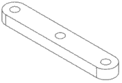
The graphics of Fig. 8 first follower link
The graphics of Fig. 9 second follower link
The graphics of Figure 10 motor shaft connecting rod
The graphics of Figure 11 motor cabinet connecting rod
The graphics of Figure 12 first corner member
The graphics of Figure 13 second corner member
The graphics of Figure 14 method of three turning angles member
The graphics of Figure 15 the 4th corner member
The graphics of Figure 16 spherical shell
The graphics of Figure 17 guide rod
Figure 18 a, Figure 18 b, Figure 18 c are the step change exploded drawings of the variable quadrangle rolling robot of step-length:
Figure 18 a minimum edge long status
Figure 18 b intermediate length state
Figure 18 c maximal side state
Figure 19 a, Figure 19 b, Figure 19 c, Figure 19 d are the variable quadrangle rolling robot craspedodrome gait exploded drawings of step-length:
The initial pose of Figure 19 a craspedodrome gait
The centre-of gravity shift action of Figure 19 b craspedodrome gait
The rolling action of Figure 19 c craspedodrome gait
The pose recovery action of Figure 19 d craspedodrome gait
Among the figure: fork unit a, driven fork unit b, the first bar group A, the second bar group B, the 3rd bar group C, the 4th bar group D of cutting are cut in first follower link 1, motor shaft connecting rod 2, second follower link 3, motor cabinet connecting rod 4, major axis 5, minor axis 6, the first corner member 7, method of three turning angles member 8, the second corner member 9, the 4th corner member 10, variable step drive motor 11, roll drive motor 12, counterweight 13, guide rod 14, protection spherical shell 15, screw 16, active.
The specific embodiment
Below in conjunction with accompanying drawing the present invention is described in further details.
The variable quadrangle rolling robot of step-length as shown in Figure 1, comprise first to fourth bar group (A, B, C, D), eight protections spherical shell (15) and a roll drive motor (12) and seven counterweights (13), wherein, the first bar group (A) and the 3rd bar group (C) comprise that separately an active cuts fork unit (a), driven four major axis and two minor axises of cutting fork unit (b), four corner members and being connected them; The second bar group (B) comprises two driven four major axis and two minor axises of cutting fork unit (b), four corner members and being connected them with the 4th bar group (D).
Embodiments of the present invention:
As Fig. 5, variable step drive motor (11) is fixing by screw and motor cabinet connecting rod (4), the interstitial hole of motor cabinet connecting rod (4) and motor shaft connecting rod (2) is passed in its rotating shaft, jackscrew is fixed the rotating shaft of motor by the top wire hole of motor shaft connecting rod (2), constitutes initiatively to cut fork unit (a).
As Fig. 6, the interstitial hole of first follower link (1) is connected by major axis (5) with the interstitial hole of second follower link (3), and carries out axial restraint with jump ring, constitutes the driven fork unit (b) of cutting.
As Fig. 3, the thick stomidium of initiatively cutting the motor cabinet connecting rod (4) in the fork unit (a) is connected by major axis (5) with a driven stomidium of cutting first follower link (1) in the fork unit (b), and carry out axial restraint with jump ring, the thin stomidium of motor cabinet connecting rod (4) is connected by minor axis (6) with the arc stomidium of first second corner member (9), and carry out axial restraint with jump ring, another stomidium of first follower link (1) is connected by major axis (5) with the arc stomidium of first first corner member (7), and carry out axial restraint with jump ring, a stomidium of initiatively cutting motor shaft connecting rod (2) in the fork unit (a) is connected by major axis (5) with the driven thick stomidium of cutting second follower link (3) in the fork unit (b), and carry out axial restraint with jump ring, another stomidium of motor shaft connecting rod (2) is connected by major axis (5) with the arc stomidium of second first corner member (7), and carry out axial restraint with jump ring, the thin stomidium of second follower link (3) is connected by minor axis (6) with the arc stomidium of second second corner member (9), and carry out axial restraint with jump ring, constitute the first bar group (A).
Structure and the connection mode of the 3rd bar group (C) are identical with the first bar group (A).
As Fig. 4, a first driven stomidium of cutting first follower link (1) in the fork unit (b) is connected by major axis (5) with the second driven thick stomidium of cutting second follower link (3) in the fork unit (b), and carry out axial restraint with jump ring, another stomidium of first follower link (1) is connected by major axis (5) with the arc stomidium of first method of three turning angles member (8), and carry out axial restraint with jump ring, the thin stomidium of second follower link (3) is connected by minor axis (6) with the arc stomidium of first the 4th corner member (10), and carries out axial restraint with jump ring; The first driven thick stomidium of cutting second follower link (3) in the fork unit (b) is connected by major axis (5) with second a driven stomidium of cutting first follower link (1) in the fork unit (b), and carry out axial restraint with jump ring, the thin stomidium of second follower link (3) is connected by minor axis (6) with the arc stomidium of second the 4th corner member (10), and carry out axial restraint with jump ring, first follower link (1) is connected by major axis (5) with the arc stomidium of second method of three turning angles member (8), and carry out axial restraint with jump ring, constitute the second bar group (B).
Structure and the connection mode of the 4th bar group (D) are identical with the second bar group (B);
As Fig. 2, the first bar group (A), the second bar group (B), the 3rd bar group (C), the 4th bar group (D), a roll drive motor (12) and seven counterweights (13) constitute parallelogram, wherein, the first bar group (A) and the 3rd bar group (C) arrange that as the opposite side of parallelogram the second bar group (B) and the 4th bar group (D) are arranged as the opposite side of parallelogram.
Roll drive motor (12) is fixed by screw with second second corner member (9) in the first bar group (A), the square end hole of second second corner member (9) in the first bar group (A) and the square end hole of second the 4th corner member (10) in the second bar group (B) are passed in the rotating shaft of roll drive motor (12), jackscrew is fixed the rotating shaft of motor by the top wire hole of the 4th corner member (10)
First counterweight (13) is fixing by first the first corner member (7) in screw and the first bar group (A), it passes the square end hole of first the first corner member (7) in the first bar group (A) and the square end hole of first method of three turning angles member (8) in the second bar group (B)
Second counterweight (13) is fixing by second first corner member (7) in screw and the 3rd bar group (C), it passes the square end hole of second first corner member (7) in the 3rd bar group (C) and the square end hole of second method of three turning angles member (8) in the second bar group (B)
The 3rd counterweight (13) is fixing by first the second corner member (9) in screw and the 3rd bar group (C), it passes the square end hole of first the second corner member (9) in the 3rd bar group (C) and the square end hole of first the 4th corner member (10) in the second bar group (B)
The 4th counterweight (13) is fixing by second second corner member (9) in screw and the 3rd bar group (C), it passes the square end hole of second second corner member (9) in the 3rd bar group (C) and the square end hole of second the 4th corner member (10) in the 4th bar group (D)
The 5th counterweight (13) is fixing by first the first corner member (7) in screw and the 3rd bar group (C), it passes the square end hole of first the first corner member (7) in the 3rd bar group (C) and the square end hole of first method of three turning angles member (8) in the 4th bar group (D)
The 6th counterweight (13) is fixing by second first corner member (7) in screw and the first bar group (A), it passes the square end hole of second first corner member (7) in the first bar group (A) and the square end hole of second method of three turning angles member (8) in the 4th bar group (D)
The 7th counterweight (13) is fixing by first the second corner member (9) in screw and the first bar group (A), and it passes the square end hole of first the second corner member (9) in the first bar group (A) and the square end hole of first the 4th corner member (10) in the 4th bar group (D).
As Fig. 1, the similar parallelogram of quadrangle rolling robot profile that step-length is variable, two protection spherical shells need be installed in each summit, and the mounting means at each place, summit is identical.One of them place, summit, the thread end of first guide rod (14) is fixed on the neutral threaded hole of the 4th corner member (10), and the screw hole that screw (16) passes on the second corner member (9) is fixed on the tapped bore of protection spherical shell (15); The thread end of second guide rod (14) is fixed on the neutral threaded hole of the first corner member (7), and the screw hole that screw (16) passes method of three turning angles member (8) is fixed on the tapped bore of protection spherical shell (15).
Arc stomidium on the described first corner member (7), the second corner member (9), method of three turning angles member (8) and the 4th corner member (10) and the axis in square end hole are orthogonal.
Concrete using method:
The variable quadrangle rolling robot of step-length can be realized the variable step function.The variable quadrangle rolling robot of step-length is in the minimum edge long status shown in the accompanying drawing 18a, at this moment, drive the variable step drive motor on the first bar group and the 3rd bar group, make tetragonal limit extend, the intermediate length state of arrival shown in accompanying drawing 18b, continue control variable step drive motor, it is the longest to make that tetragonal limit is elongated to, and arrives the maximal side state shown in accompanying drawing 18c.So just realized the step change process of the quadrangle rolling robot of variable step, Figure 18 a, Figure 18 b, Figure 18 c are the step change exploded drawingss of the variable quadrangle rolling robot of step-length.
The variable quadrangle rolling robot of step-length can be realized the gait of keeping straight on.At first the variable quadrangle rolling robot of step-length is in the initial pose of the craspedodrome gait shown in accompanying drawing 19a, holding the tetragonal limit of row level with both hands with direct of travel is bearing surface, by control roll drive motor, the angle that changes the parallelogram interior angle changes, the craspedodrome gait centre-of gravity shift action of realization shown in accompanying drawing 19b, because action of inertia, the variable quadrangle rolling robot of step-length rolls, this moment, the another side as the parallelogram that supports landed, the craspedodrome gait rolling action of realization shown in accompanying drawing 19c, control the motion of roll drive motor again, change the angle of parallelogram interior angle, the attitude of the craspedodrome gait appearance of realization shown in accompanying drawing 19d is recovered action, and the variable quadrangle rolling robot of step-length returns to incipient state.So just realized a complete craspedodrome gait of robot, the variable quadrangle rolling robot of step-length is finished this process repeatedly and just can be realized advancing forward of robot.Figure 19 a, Figure 19 b, Figure 19 c, Figure 19 d are the exploded drawingss of the variable quadrangle rolling robot craspedodrome gait of step-length.
Claims (3)
1. the variable quadrangle rolling robot of step-length, it is characterized in that: the variable quadrangle rolling robot of step-length comprises first to fourth bar group (A, B, C, D), eight protections spherical shell (15) and a roll drive motor (12) and seven counterweights (13), wherein, the first bar group (A) and the 3rd bar group (C) comprise that separately an active cuts fork unit (a), driven four major axis and two minor axises of cutting fork unit (b), four corner members and being connected them; The second bar group (B) comprises two driven four major axis and two minor axises of cutting fork unit (b), four corner members and being connected them with the 4th bar group (D);
Described active is cut in the fork unit (a), variable step drive motor (11) is fixing by screw and motor cabinet connecting rod (4), the interstitial hole of motor cabinet connecting rod (4) and motor shaft connecting rod (2) is passed in its rotating shaft, and jackscrew is fixed the rotating shaft of motor by the top wire hole of motor shaft connecting rod (2);
Described driven cutting in the fork unit (b), the interstitial hole of first follower link (1) is connected by major axis (5) with the interstitial hole of second follower link (3), and carries out axial restraint with jump ring;
In the described first bar group (A), the thick stomidium of initiatively cutting the motor cabinet connecting rod (4) in the fork unit (a) is connected by major axis (5) with a driven stomidium of cutting first follower link (1) in the fork unit (b), and carry out axial restraint with jump ring, the thin stomidium of motor cabinet connecting rod (4) is connected by minor axis (6) with the arc stomidium of first second corner member (9), and carry out axial restraint with jump ring, another stomidium of first follower link (1) is connected by major axis (5) with the arc stomidium of first first corner member (7), and carry out axial restraint with jump ring, a stomidium of initiatively cutting motor shaft connecting rod (2) in the fork unit (a) is connected by major axis (5) with the driven thick stomidium of cutting second follower link (3) in the fork unit (b), and carry out axial restraint with jump ring, another stomidium of motor shaft connecting rod (2) is connected by major axis (5) with the arc stomidium of second first corner member (7), and carry out axial restraint with jump ring, the thin stomidium of second follower link (3) is connected by minor axis (6) with the arc stomidium of second second corner member (9), and carries out axial restraint with jump ring;
Structure and the connection mode of the 3rd bar group (C) are identical with the first bar group (A);
In the described second bar group (B), a first driven stomidium of cutting first follower link (1) in the fork unit (b) is connected by major axis (5) with the second driven thick stomidium of cutting second follower link (3) in the fork unit (b), and carry out axial restraint with jump ring, another stomidium of first follower link (1) is connected by major axis (5) with the arc stomidium of first method of three turning angles member (8), and carry out axial restraint with jump ring, the thin stomidium of second follower link (3) is connected by minor axis (6) with the arc stomidium of first the 4th corner member (10), and carries out axial restraint with jump ring; The first driven thick stomidium of cutting second follower link (3) in the fork unit (b) is connected by major axis (5) with second a driven stomidium of cutting first follower link (1) in the fork unit (b), and carry out axial restraint with jump ring, the thin stomidium of second follower link (3) is connected by minor axis (6) with the arc stomidium of second the 4th corner member (10), and carry out axial restraint with jump ring, first follower link (1) is connected by major axis (5) with the arc stomidium of second method of three turning angles member (8), and carries out axial restraint with jump ring;
Structure and the connection mode of the 4th bar group (D) are identical with the second bar group (B);
The first bar group (A), the second bar group (B), the 3rd bar group (C), the 4th bar group (D), a roll drive motor (12) and seven counterweights (13) constitute parallelogram, wherein, the first bar group (A) and the 3rd bar group (C) arrange that as the opposite side of parallelogram the second bar group (B) and the 4th bar group (D) are arranged as the opposite side of parallelogram;
Roll drive motor (12) is fixed by screw with second second corner member (9) in the first bar group (A), the square end hole of second second corner member (9) in the first bar group (A) and the square end hole of second the 4th corner member (10) in the second bar group (B) are passed in the rotating shaft of roll drive motor (12), jackscrew is fixed the rotating shaft of motor by the top wire hole of the 4th corner member (10)
First counterweight (13) is fixing by first the first corner member (7) in screw and the first bar group (A), it passes the square end hole of first the first corner member (7) in the first bar group (A) and the square end hole of first method of three turning angles member (8) in the second bar group (B)
Second counterweight (13) is fixing by second first corner member (7) in screw and the 3rd bar group (C), it passes the square end hole of second first corner member (7) in the 3rd bar group (C) and the square end hole of second method of three turning angles member (8) in the second bar group (B)
The 3rd counterweight (13) is fixing by first the second corner member (9) in screw and the 3rd bar group (C), it passes the square end hole of first the second corner member (9) in the 3rd bar group (C) and the square end hole of first the 4th corner member (10) in the second bar group (B)
The 4th counterweight (13) is fixing by second second corner member (9) in screw and the 3rd bar group (C), it passes the square end hole of second second corner member (9) in the 3rd bar group (C) and the square end hole of second the 4th corner member (10) in the 4th bar group (D)
The 5th counterweight (13) is fixing by first the first corner member (7) in screw and the 3rd bar group (C), it passes the square end hole of first the first corner member (7) in the 3rd bar group (C) and the square end hole of first method of three turning angles member (8) in the 4th bar group (D)
The 6th counterweight (13) is fixing by second first corner member (7) in screw and the first bar group (A), it passes the square end hole of second first corner member (7) in the first bar group (A) and the square end hole of second method of three turning angles member (8) in the 4th bar group (D)
The 7th counterweight (13) is fixing by first the second corner member (9) in screw and the first bar group (A), and it passes the square end hole of first the second corner member (9) in the first bar group (A) and the square end hole of first the 4th corner member (10) in the 4th bar group (D).
2. the variable quadrangle rolling robot of step-length as claimed in claim 1, it is characterized in that: the similar parallelogram of quadrangle rolling robot profile that step-length is variable, two protection spherical shells are installed on each summit of parallelogram, and the mounting means at each place, summit is similar, one of them place, summit, the thread end of first guide rod (14) is fixed on the neutral threaded hole of the 4th corner member (10), and the screw hole that screw (16) passes on the second corner member (9) is fixed on the tapped bore of protection spherical shell (15); The thread end of second guide rod (14) is fixed on the neutral threaded hole of the first corner member (7), and the screw hole that screw (16) passes method of three turning angles member (8) is fixed on the tapped bore of protection spherical shell (15).
3. the variable quadrangle rolling robot of step-length as claimed in claim 1, it is characterized in that: the arc stomidium on the first corner member (7), the second corner member (9), method of three turning angles member (8) and the 4th corner member (10) and the axis in square end hole are orthogonal.
Priority Applications (1)
| Application Number | Priority Date | Filing Date | Title |
|---|---|---|---|
| CN201310276594.4A CN103303385B (en) | 2013-07-03 | 2013-07-03 | The quadrangle rolling robot that step-length is variable |
Applications Claiming Priority (1)
| Application Number | Priority Date | Filing Date | Title |
|---|---|---|---|
| CN201310276594.4A CN103303385B (en) | 2013-07-03 | 2013-07-03 | The quadrangle rolling robot that step-length is variable |
Publications (2)
| Publication Number | Publication Date |
|---|---|
| CN103303385A true CN103303385A (en) | 2013-09-18 |
| CN103303385B CN103303385B (en) | 2015-08-05 |
Family
ID=49129205
Family Applications (1)
| Application Number | Title | Priority Date | Filing Date |
|---|---|---|---|
| CN201310276594.4A Active CN103303385B (en) | 2013-07-03 | 2013-07-03 | The quadrangle rolling robot that step-length is variable |
Country Status (1)
| Country | Link |
|---|---|
| CN (1) | CN103303385B (en) |
Cited By (2)
| Publication number | Priority date | Publication date | Assignee | Title |
|---|---|---|---|---|
| CN107215370A (en) * | 2017-05-23 | 2017-09-29 | 安溪县智睿电子商务有限公司 | A kind of handling device with cat ladder function for smart home |
| FR3126905A1 (en) * | 2021-09-15 | 2023-03-17 | Nimble One | New mobile robotic system architecture |
Citations (5)
| Publication number | Priority date | Publication date | Assignee | Title |
|---|---|---|---|---|
| US5161631A (en) * | 1989-11-27 | 1992-11-10 | Uragami Fukashi | Suction device capable of moving along a surface |
| GB2292355A (en) * | 1994-08-06 | 1996-02-21 | Thomas Leith Taig | A machine for moving over vertical and horizontal surfaces |
| CN2789106Y (en) * | 2005-04-08 | 2006-06-21 | 北京交通大学 | Single-power rolling four-bar mechanism |
| CN101462561A (en) * | 2009-01-13 | 2009-06-24 | 北京交通大学 | Rolling triangular robot |
| CN102615649A (en) * | 2012-04-11 | 2012-08-01 | 北京交通大学 | Rolling double four-parallelogram robot |
-
2013
- 2013-07-03 CN CN201310276594.4A patent/CN103303385B/en active Active
Patent Citations (5)
| Publication number | Priority date | Publication date | Assignee | Title |
|---|---|---|---|---|
| US5161631A (en) * | 1989-11-27 | 1992-11-10 | Uragami Fukashi | Suction device capable of moving along a surface |
| GB2292355A (en) * | 1994-08-06 | 1996-02-21 | Thomas Leith Taig | A machine for moving over vertical and horizontal surfaces |
| CN2789106Y (en) * | 2005-04-08 | 2006-06-21 | 北京交通大学 | Single-power rolling four-bar mechanism |
| CN101462561A (en) * | 2009-01-13 | 2009-06-24 | 北京交通大学 | Rolling triangular robot |
| CN102615649A (en) * | 2012-04-11 | 2012-08-01 | 北京交通大学 | Rolling double four-parallelogram robot |
Cited By (3)
| Publication number | Priority date | Publication date | Assignee | Title |
|---|---|---|---|---|
| CN107215370A (en) * | 2017-05-23 | 2017-09-29 | 安溪县智睿电子商务有限公司 | A kind of handling device with cat ladder function for smart home |
| FR3126905A1 (en) * | 2021-09-15 | 2023-03-17 | Nimble One | New mobile robotic system architecture |
| WO2023041592A1 (en) | 2021-09-15 | 2023-03-23 | Nimble One | New architecture for a mobile robotic system |
Also Published As
| Publication number | Publication date |
|---|---|
| CN103303385B (en) | 2015-08-05 |
Similar Documents
| Publication | Publication Date | Title |
|---|---|---|
| CN102615649B (en) | Rolling double four-parallelogram robot | |
| CN102514645B (en) | Spherical rolling robot | |
| CN102632936B (en) | Rollingly-marching robot with two wheel-like hexagonal mechanisms | |
| CN103129735B (en) | Three sections of twofold wings | |
| CN204998759U (en) | Collapsible undercarriage of moving away to avoid possible earthquakes | |
| CN102380771B (en) | High-rigidity redundantly-actuated three-degree-of-freedom parallel mechanism | |
| CN107639649B (en) | Permanent magnet variable-rigidity flexible joint for robot | |
| CN102058982B (en) | Single-power rolling polygonal mechanism | |
| CN103737209A (en) | Welding robot with symmetrical mechanisms | |
| CN103737208A (en) | Multi-degree-of-freedom welding robot | |
| CN105314109B (en) | A kind of wing drive mechanism of flapping wing aircraft | |
| CN107472389B (en) | Bouncing robot capable of actively adjusting posture before landing | |
| CN103522279A (en) | Full symmetric space three-rotational-freedom parallel mechanism | |
| CN102672707B (en) | Differential seven-connecting-rod robot traveling in rolling way | |
| CN103303385A (en) | Quadrilateral rolling robot with variable step length | |
| CN102673669A (en) | Polyhedral rolling mechanism | |
| CN102126216A (en) | Symmetrical-structure parallel mechanism having two-turn-one-shift three degrees of freedom | |
| CN109531558B (en) | Single-power mobile five-rod robot | |
| CN102615644A (en) | Novel posture adjustment mechanism capable of achieving three-rotation one-translation degree of freedom | |
| CN103144691B (en) | Six degree of freedom rolling mechanism | |
| CN104589309A (en) | Multi-freedom-degree parallel mechanism type controllable mobile welding robot | |
| CN205220850U (en) | Multi -functional robot that hinders more | |
| US8460050B2 (en) | Transmission mechanism for remote-controlled toy helicopter | |
| CN204973019U (en) | 6 -degree of freedom game station base device | |
| RU167129U1 (en) | COMBINED SPHERAL WORK |
Legal Events
| Date | Code | Title | Description |
|---|---|---|---|
| C06 | Publication | ||
| PB01 | Publication | ||
| C10 | Entry into substantive examination | ||
| SE01 | Entry into force of request for substantive examination | ||
| C14 | Grant of patent or utility model | ||
| GR01 | Patent grant |