CN1031212C - Control method and microcomputer automatic control system of rotary drill - Google Patents
Control method and microcomputer automatic control system of rotary drill Download PDFInfo
- Publication number
- CN1031212C CN1031212C CN 92106897 CN92106897A CN1031212C CN 1031212 C CN1031212 C CN 1031212C CN 92106897 CN92106897 CN 92106897 CN 92106897 A CN92106897 A CN 92106897A CN 1031212 C CN1031212 C CN 1031212C
- Authority
- CN
- China
- Prior art keywords
- drilling tool
- drilling
- axial compression
- rig
- vibration
- Prior art date
- Legal status (The legal status is an assumption and is not a legal conclusion. Google has not performed a legal analysis and makes no representation as to the accuracy of the status listed.)
- Expired - Fee Related
Links
Images


Abstract
A control method and a microcomputer automatic control system of a roller-bit drill relate to the control technology of the drilling process and the leveling operation of the roller-bit drill and the automatic recording of the lithology of the drilled hole. The invention provides a control method and a microcomputer automatic control system for the drilling process of a roller-bit drill, which can ensure that the drill is optimally matched with the rotating speed and the axial pressure of a drilling tool according to the change of a drilled rock stratum, and ensure that the drill is in an excellent drilling state. The basis of the invention is a rock drillability index for cone drilling, which characterizes the degree of resistance of the rock to bit crushing during cone drilling. The system utilizes a unique control model that relates the rotational speed and axial pressure of the drilling tool to the properties of the rock formation being drilled, the rotational torque, and the amount of overrun in the drill vibration.
Description
The present invention is a kind of control method and microcomputer automatic control system of rotary drill, and it relates to the automatic record of the control technology and the boring lithology of rotary drill boring procedure and leveling operation.Can make rig realize the optimization coupling of drilling tool rotating speed and drilling tool axial compression making rig be in the good state that creeps into according to the variation of drilled rock drilling layer.
Rotary drill is the advanced efficient rig that present domestic and international big-and-middle-sized surface mine widely uses, and is undertaking the boring amount of surface mine ore deposit rock exploitation total amount more than 80%, occupies extremely important status in the mine produces.For the high-quality big gun hole of giving a farfetched interpretation, rig need have complete operation sequence and the adjustment process of a cover.At first will be rig leveling on rough work plane, could hole then, must take low rotating speed and low axial compression to creep into during perforate, when in case drill bit contacts hard rock stratum, will increase the speed of gyration and the axial pressure of drilling tool, obtaining higher rate of penetration, might not be that the best of rig is crept into state but apply greatest axis pressure and speed of gyration.According to rock-cracking mechanism, when the axial pressure of rock bit makes cutter teeth contact the contact pressure that is produced with rock to be equal to or greater than the ultimate strength of rock, rock just produces effective volume fragmentation, broken rock solid impurity particle is big, be equipped with suitable speed of gyration and stronger deslagging ability again, just can reach higher penetration rate.This shows in drilling process, a problem that realizes optimizing coupling drilling tool rotating speed and drilling tool axial compression according to the variation of rock stratum is arranged.The rotary drill drilling parameter has drilling tool rotation speed n, drilling tool axial compression P, rate of penetration V, revolution to move square M, rig vibration λ, delivery of bailing air Q and pressure of bailing air P
FDeng, wherein drilling tool rotation speed n, drilling tool axial compression P and delivery of bailing air Q are basic drilling parameters.The delivery of bailing air Q of rig is non-adjustable at present, and therefore, the basic adjustment parameter of drilling process is drilling tool rotation speed n and drilling tool axial compression P.The method of representational in the past adjusting drilling tool rotating speed and drilling tool axial compression has two kinds: (1) asks extremum method to benefit criterion N=(V/n)/(M/P)=PV/nM.Wherein power is crept in the PV representative, nM representative revolution power.The physical meaning of criterion N is for creeping into the ratio of power and revolution power, and the Optimum Matching of seeking axial compression and rotating speed by the benefit criterion becomes maximum under the unit's of seeking revolution power and creeps into power and mate drilling tool rotating speed and drilling tool axial compression like this.From rock bit fractured rock mechanism, this criterion has maximum in theory, but actual tests shows, because the maximum axial compression of existing rotary drill is subjected to the restriction of frame for movement, therefore its value can not find optimum axial compression much smaller than the best axial compression of seeking by criterion N.And what in fact find is the maximum axial compression of rig and the rotating speed of correspondence with it, and therefore, this method does not have much use value, because the maximum axial compression of rig and the rotating speed corresponding with it need not to seek just can provide.(2) maximum rate of penetration method.At rotary torque M<M
Max, rig vibration λ<λ
MaxUnder constraints, according to V=φ (n, P) → V
MaxRegulate drilling tool rotation speed n and drilling tool axial compression P.But rotary drill creeps into actual conditions to be shown, in general, drilling tool is applied maximum axial compression and maximum speed can obtain maximum rate of penetration, but can not obtain high bit life and low boring cost.
The objective of the invention is to propose a kind of control method and microcomputer automatic control system of rotary drill, comprise the control method and the control device of rotary drill drilling process.The roller boring rock drillability index of continuous detecting lithology in the roller boring process has promptly been proposed, reflect the variation of drilled rock drilling layer by it, make the rig can be according to the variation of rock stratum, optimize coupling drilling tool rotating speed and drilling tool axial compression, reach the good state that creeps into, be implemented in the target that higher rate of penetration is issued to high drilling life of bit and low boring cost.
The present invention utilizes a kind of unique control model, makes rotary drill in drilling process, and the drilling tool rotating speed is relevant with the amount of transfiniting of character, rotary torque and the rig vibration of drilled rock drilling layer with the drilling tool axial compression.Basis of the present invention is roller boring rock drillability index D
I, characterize in the roller boring process rock to the impedance level of drill bit fragmentation by it, its be defined as brill that drilling tool whenever goes around deeply with the ratio of drilling tool axial compression, that is:
In the formula, V/n is that the drilling tool brill of whenever going around under the effect of axial compression P is dark, and n is the drilling tool rotating speed, and P is the drilling tool axial compression, and V is a rate of penetration.
Rock drillability index is relevant with the shape of size, structure and the tooth of drill bit, and concerning the drill bit that uses a certain specifications and models, rock drillability index can reflect the complexity that rock can bore, and its value is big more, shows the easy more brill of rock; Its value is more little, shows the difficult more brill of rock.Therefore, rig by the continuous detecting drilling tool rotation speed n of now, drilling tool axial compression P and rate of penetration V, just can be calculated roller boring rock drillability index DI=V/Pn in drilling process, mate drilling tool rotating speed and drilling tool axial compression by it.Roller boring rock-cracking mechanism shows, required rotating speed of drilling tool and D
IBe directly proportional, and required axial compression of drilling tool and D
IBe inversely proportional to, can draw the given signal n ' of drilling tool rotating speed and drilling tool axial compression thus
gAnd P '
gRelational expression:
n′
g=n
0+K
1D
I In the formula, n
0Be the adjustable constant relevant, P with the rig minimum operating speed
0For being pressed with the adjustable constant of pass with the minimum working shaft of rig; K
1Be roller boring rock drillability index D
ITo the adjustability coefficients of drilling tool rotating speed influence, K
3Be roller boring rock drillability index D
IAdjustability coefficients to drilling tool axial compression influence.
In addition, utilize rig vibration λ (comprising vertical vibration and horizontal vibration) and rotary torque M to proofread and correct drilling tool rotation speed n and drilling tool axial compression P respectively, when rig vibration and rotary torque are no more than predetermined lower limit setting valve λ
dAnd M
dThe time, these two correction terms are inoperative, have only when rig vibration or rotary torque to surpass predetermined lower limit setting valve λ
dOr M
dThe time, just according to the reduction drilling tool rotating speed of the amount of transfiniting or the given signal of drilling tool axial compression, can draw drilling tool rotating speed and the given signal n of drilling tool axial compression when rig vibration and rotary torque transfinite thus with being in proportion
gAnd P
gRelational expression:
n
g=n'
g-K
2Δλ=n
0+K
1D
I-K
2Δλ
In the formula, K
2Be the adjustability coefficients of the rig vibration amount of transfiniting size to drilling tool rotational speed setup effect of signals; K
4Be the adjustability coefficients of the rotary torque amount of transfiniting size to the given effect of signals of drilling tool axial compression; Δ λ is the rig vibration amount of transfiniting, and Δ M is the rotary torque amount of transfiniting.
Δλ=λ-λ
d
Δ M=M-M
dIn the formula, λ
dBe the lower limit setting valve of rig vibration, M
dLower limit setting valve for rotary torque.
As long as, reasonably select adjustable constant n according to the different size model of rig and drill bit
0And P
0And adjustability coefficients K
1, K
2, K
3And K
4, just can realize optimizing coupling drilling tool rotating speed and drilling tool axial compression.
In addition, the present invention has designed a kind of rotary drill microcomputer automatic control system and control application software thereof of special use, realizes above-mentioned control method by it, and as long as by revising adjustable constant n simply
0And P
0And adjustability coefficients K
1, K
2, K
3And K
4, just can make its rotary drill that is applicable to different size and model and drill bit.
Microcomputer automatic control system provided by the invention comprises drilling process optimal control device, the rotary torque treating apparatus that transfinites, the rig vibration treating apparatus that transfinites, the pressure of bailing air treating apparatus that transfinites, the drilling process presetting apparatus, the flat gradient of rig detects demonstration and instructs levelling device, boring rock stratum information record carrier.These devices are made up of different drilling parameter signal supervisory instruments, arithmetic unit, microcomputer data acquisition, calculating, treating apparatus, axial compression adjuster, speed regulator, lifting executing agency, water filling executing agency, alarm and cassette type recording device respectively by its function.
Fig. 1 is a rotary drill microcomputer automatic control system calcspar;
Fig. 2 is an arithmetic unit principle calcspar;
Fig. 3 is the rotary drill control inner composition diagram of microsystem;
Fig. 4 is the calcspar of an example of drilling tool axial compression adjuster;
Fig. 5 is a digital trigger principle calcspar;
Fig. 6 is the calcspar of another example of drilling tool axial compression adjuster;
Fig. 7 is a drilling tool speed regulator calcspar;
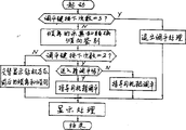
Fig. 8 is a drilling process optimal control flow chart;
Fig. 9 is that the flat gradient of rotary drill detects the flow chart that shows and instruct leveling.
Rotary drill microcomputer automatic control system shown in Figure 1 comprises: the drilling parameter signal supervisory instrument has drilling tool speed detector 1, drilling tool axial compression checkout gear 2, rate of penetration checkout gear 3, rotary torque checkout gear 5, rig vibration checkout gear 6, pressure of bailing air checkout gear 7, rig left and right sides inclination detecting device 4, rig anteversion and retroversion angle detecting device 9, rig tendency checkout gear 10, drilling depth checkout gear 11; With good grounds drilling tool rotating speed of arithmetic unit and drilling tool axial compression signal produce the arithmetic unit 4 of drilling tool working state signal, produce roller boring rock drillability index and arithmetic unit 12 and 13 reciprocal thereof respectively according to drilling tool working state signal and rate of penetration signal; And the rotary torque that checkout gear 5,6,8,9 is produced, rig synthesis oscillation, inclination angle, the rig left and right sides, the analog signals at inclination angle converts digital quantity signal to and converts roller boring rock drillability index and analog value reciprocal thereof that arithmetic unit 12,13 produces respectively to digital quantity value before and after the rig, and produces the special microprocessor system 14 of the given signal of drilling tool rotating speed and drilling tool axial compression thus; According to the given signal of drilling tool axial compression the axial compression adjuster 15 that proportional integral is regulated is carried out in the drilling tool axial compression; The drilling tool rotating speed is regulated the speed regulator 16 of control according to drilling tool rotational speed setup signal; Promote executing agency 17; Water filling executing agency 18; Alarm 19 and cassette type recording device 20.
The checkout gear of the main drilling parameter of rotary drill requires simple and reliable, and is applicable to mine bad working environment and condition.By the reducer driven rotary, therefore, the rotating speed of turning motor just can reflect the drilling tool rotating speed to the drilling tool of rotary drill by turning motor.For YZ and KY two big serial rotary drills, turning motor all is its sharp DC motor, because turning motor is installed on the rotary machinery, and move up and down along drilling cramp with rotary machinery at any time, so its rotating speed is difficult to measure with the coaxial connection of tachometer generator, for this reason, the drilling tool rotating speed carries out approximate measure by the armature voltage that detects turning motor.For the ease of isolating with the forceful electric power main circuit, drilling tool speed detector 1 is made up of DC current transformer and signal processing circuit thereof after improving.
The rig of different series, the applying method of its rig axial compression is different, rotary drill for YZ series, the drilling tool axial compression is applied by main machine frame reducer, sealed joint-rack gearing by the hydraulic pressurization motor, therefore drilling tool axial compression and hydraulic motor two ends oil pressure are proportional, so the detection of drilling tool axial compression can become the detection to hydraulic pressurization motor oil pressure.Drilling tool axial compression checkout gear 2 is made up of teletransmission pressure meter and amplifying circuit thereof after improving, and the teletransmission pressure meter after the improvement is connected on the oil-in pipeline of hydraulic pressurization motor.For KY series rotary drill, the axial compression of drilling tool is applied by main machine frame reducer, sealed joint-rack gearing by electromagnetic coupling asynchronous motor, therefore the moment of torsion of the axial compression of drilling tool and electromagnetic coupling asynchronous motor is proportional, so drilling tool axial compression checkout gear 2 becomes the device of the active component of current that detects the pressurization motor.
Rate of penetration is exactly the fltting speed of drilling tool, and the rotating speed of it and compression motor (or motor) and main machine frame reference axis is proportional.Fltting speed is discontinuous when considering actual creeping into, and is especially more outstanding when Drilling hard rock or ore, therefore, from detecting the filtering requirements of average rate of penetration, detects to well from compression motor (or motor) or high speed shaft.Consider easy for installationly, adopt the impulse type speed probe and it is installed on the pressuring shaft and detect.When rig crept into, the rate of penetration sensor sent a series of frequencies and the proportional pulse of rate of penetration, and rate of penetration checkout gear 3 for control usefulness, shows for rate of penetration on the one hand on the other hand in order to these pulse signals are become voltage signal.
Be used for the roller boring rock drillability index D that drilling tool rotating speed and drilling tool axial compression are regulated
IAnd it is reciprocal
Be individual very important parameters,, improve the rapidity of control system, the special hardware arithmetic unit 4,12 and 13 that adopts in order to accelerate its arithmetic speed.At first, drilling tool rotation speed n and the drilling tool axial compression P that drilling tool rotating speed and drilling tool axial compression checkout gear record in real time, try to achieve the working state signal S of drilling tool by the multiplying of arithmetic unit 4
D=P
n, then by drilling tool working state signal S
DTry to achieve roller boring rock drillability index D by the division arithmetic of arithmetic unit 12 and 13 respectively with rate of penetration signal V
IAnd it is reciprocal
 That is:
Arithmetic unit 4,12 and 13 all is multi-functional multiplier-divider, and it partly is made up of logarithm operational amplifier 21, logarithm ratio operational amplifier 22, adder 23 and operational amplifier of the antilogarithm 24 etc., its principle calcspar as shown in Figure 2, its input-output characteristic is:
As input V
Y=n, V
Z=P, V
X=C
1(constant, a corresponding fixed voltage), then V
0=nP/C
1=CnP plays the multiplication effect of arithmetic unit 4.As input V
Y=V, V
X=S
D=Pn, and V
Z=C
2(constant, a corresponding fixed voltage), then V
0=C
2V/Pn plays the division effect of arithmetic unit 12.As input V
Y=S
D=Pn, V
X=V, and V
Z=C
3(constant, a corresponding fixed voltage), then V
0=C
3Pn/V plays the division effect of arithmetic unit 13.
The special microprocessor system 14 of rotary drill control usefulness shown in Figure 3 is made up of CPU board 25, A/D converter plate 26, parallel interface and timer plate 27, D/A conversion and rotational speed setup device plate 28, control 29,4 photoelectric digital tube displays 30 of input keyboard and cassette tape recorder interface board 31 etc.Wherein EPROM on the CPU board and RAM are used for depositing the roller boring rock drillability index of control program and reflection boring lithology respectively; A/D converter plate 26 with 8 tunnel 8 A/D input receives respectively through each checkout gear and amplifies drilling parameter signal after handling, as angle of inclination beta before and after rotary torque M, rig vibration λ, roller boring rock drillability index V/Pn and Pn/V reciprocal thereof, rig left and right sides inclination alpha and the rig; Parallel interface is connected with alarm 19 with control input keyboard 29, display 30, drilling tool axial compression adjuster 15, lifting executing agency 17, water filling executing agency 18 respectively with timer plate 27; D/A conversion and rotational speed setup device plate 28 convert analog quantity in order to the drilling tool rotational speed setup signal that microcomputer is provided to by digital quantity, and are added to the input of drilling tool speed regulator 16 by the rotational speed setup device; Cassette tape recorder interface board 31 is in order to be dumped to outside cassette tape recorder 20 to the rock drillability index that is stored in the reflection boring lithology among the CPU board RAM.In addition, reflection drilling depth H creeps into dfisplacement pulse and promotes two external interrupt application ends that dfisplacement pulse is added to CPU respectively, the tendency signal of the transfinite signal and the reflection drilling machine platform incline direction of pressure of bailing air all is input to the input port of CPU with the switching value form, microsystem 14 is used for collection, processing, calculating and the control of each drilling parameter.
The given signal of axial compression that drilling tool axial compression adjuster 15 provides according to computer carries out proportional integral to axial compression to be regulated, and its calcspar as shown in Figure 4.The middle feedback device 35 of the digital governer 32 that it is made up of microcomputer and software thereof, controlled rectifier 33, electricity-liquid proportional pressure regulator valve 34 and axial compression etc. is formed.Drilling tool axial compression adjuster is regulated by 36 pairs of drilling tool axial compressions of hydraulic loading system again.Hydraulic loading system 36 is made up of hydraulic system 37, electricity-liquid direction valve 38, hydraulic pressurization motor 39 and pressing mechanism 40 etc.
Digital governer 32 comprises three parts compositions such as proportional and integral controller 42, axial compression numeral control point adjustment 41 and digital trigger 43, and axial compression numeral control point adjustment 41 provides the given signal P of axial compression of optimization according to the variation of creeping into the rock stratum
g(t), with axial compression intermediate feedback signals P
k(t) compare, obtain difference signal E (t)=P
g(t)-P
k(t), by software its difference signal is carried out proportional integral computing and adjusting then.The calcspar of digital trigger 43 as shown in Figure 5, it is by synchronous generator 44, regularly links such as phase shifter 46, pulse stretcher 47, photoisolator 45 and trigger impulse power amplifier 48 are formed.Synchronous generator 44 is used for producing the 50Hz synchronization pulse, and one is as computer sync break control signal, by the control of its synchronous whole Control System of Microcomputer; Its two synchronizing signal as axial compression adjuster power amplifier level controlled rectifier, synchronous to guarantee IGCT anode voltage and trigger impulse.Synchronous generator 44 sends synchronous burst pulse at 50Hz alternating current zero crossing place, and this pulse width is suitable, otherwise can influence control action.Burst pulse is added to the timer T of CPU board after photoisolator 45 is isolated synchronously
1The input application interrupt, CPU enters the Synchronization Control interrupt service routine immediately after application is interrupted in response, the last cycle calculate the phase shift timing value insert in the timing phase shifter 46 of parallel interface and timer plate 27, and start the timing phase shift immediately.Then the axial compression intermediate feedback signals is sampled and difference is carried out the proportional integral computing, calculate at last the phase shift timing value deposit internal memory in, for next use synchronizing cycle.When the timing phase shifter is timed to, by pulse of its output, behind monostable pulse stretcher 47 broadenings, by photoisolator 45 and power amplifier 48, by pulse transformer output trigger impulse.Controlled rectifier 33 is single-phase half-controlled bridge-type rectification circuits, by it the axial compression conditioning signal is carried out power amplification.In order to guarantee the linearity, phase shifting angle is controlled between 90 °~180 °, the output of controlled rectifier is added on the electromagnet coil of electricity-liquid proportional pressure regulator valve.Electricity-liquid proportional pressure regulator valve 34 is a kind of electricity-liquid elements that can carry out the ratio adjusting in input signal to hydraulic pressurization motor oil-in pressure.
For KY series rotary drill, because its pressing mechanism adopts the electromagnetic coupling asynchronous motor transmission, so, to do some changes to above-mentioned axial compression adjuster, promptly electricity-liquid proportional pressure regulator valve 34 is changed into electromagnetic slip clutches 49, simultaneously, feedback device 35 in the middle of the axial compression is changed into the torque feedback device 50 of electromagnetic coupling asynchronous motor.In addition, hydraulic loading system 36 is changed into the compression system 51 of electromagnetic coupling asynchronous motor 52.Fig. 6 is the calcspar of this axial compression adjuster, and wherein reversing arrangement 53 promptly becomes drilling tool and creeps into to promoting in order to change the drilling direction of drilling tool.
Fig. 7 is the drilling tool speed regulator calcspar that is applicable to YZ series rotary drill, and it comprises microcomputer rotational speed setup device plate 28 and the former revolution arrangements for speed regulation 54 of rig.The drilling tool speed regulator is regulated the drilling tool rotating speed according to the optimization tach signal that computer provides.From scheming as seen, three-phase alternating-current supply is supplied with rotary dc motor 56 through IGCT three-phase controlled bridge rectifier 55, by the firing angle of the prosperous brake tube of magnetic phase-shift trigger circuit 57 controls, thereby the output voltage of change controlled rectifier 55 is realized the stepless speed regulation of turning motor 56.In order to improve the hardness of slew gear characteristic, be added with armature voltage negative-feedback 58.In order to limit the overcurrent that drilling tool stick of tool or other reason cause, be added with electric current limit feedback 59.The rotational speed setup signal n that computer provides according to the Drilling formation variations
g, export one corresponding to n by D/A converter 60
gAanalogvoltage, and after amplifier 61 amplifies de-energisation magnetic phase-shift trigger circuit 57, and then make turning motor 56 provide one and n
gCorresponding rotating speeds.For the ease of driver's manual adjustments rotating speed when non-automatic the creeping into, keep former manual governing potentiometer 62, an ad hoc manual changeover switch 63 switches.For KY series rotary drill, microcomputer rotational speed setup device plate 28 of the present invention is as long as strengthen the amplifier capacity, improves behind its output current in the same old way and the supporting use of the high-power magnetic amplifier arrangements for speed regulation of former rig.
Drilling process optimal control device is by one group of drilling parameter detecting sensor and amplifier thereof, and microcomputer data acquisition is handled and operation control device compositions such as axial compression adjuster and speed regulator.Specifically, comprise drilling tool speed detector 1, drilling tool axial compression checkout gear 2, rate of penetration checkout gear 3, rotary torque checkout gear 5, rig vibration checkout gear 6, arithmetic unit 4,12 and 13, special microprocessor system 14, axial compression adjuster 15 and speed regulator 16 (referring to Fig. 1).When the borer drilling procedure optimal control, 14 pairs of roller boring rock drillability indexs of microsystem D
IAnd it is reciprocal
 , rig vibration λ and rotary torque M carry out acquisition time, digital filtering, and calculate the drilling tool rotating speed of optimization and the given signal of drilling tool axial compression.Insert a stand-by period in control cycle, as the parameter stability time after regulating, all the other are the continuous sampling time of above-mentioned parameter.Concise and to the point drilling process optimal control program as shown in Figure 8.As can be seen from Fig. 8, when rig vibration λ greater than predetermined lower limit setting valve λ
dThe time, in the optimal control program, introducing a vibration correction item, λ reduces drilling tool rotational speed setup signal pro rata with the vibration amount of transfiniting Δ.For the resonance of bringing out by general vibration, just can eliminate as long as destroy its resonance condition by reduction drilling tool rotating speed.If 1
sThe interior limit that can not reach is vibrated requirement, shows that then this section is the difficult section that shakes that bores more, and computer changes over to and vibrates the handling procedure that transfinites.Equally, surpass predetermined lower limit setting valve M as rotary torque M
d, and less than predetermined middle limit setting valve M
mThe time, then in the optimal control program, introducing a rotary torque correction term, M reduces the given signal of drilling tool axial compression pro rata with the rotary torque amount of transfiniting Δ.When rotary torque M surpasses M
mThe time, then computer enters the rotary torque handling procedure that transfinites.Rotating speed that computer finally sends and the given signal of the optimization of axial compression go to regulate the rotating speed and the axial compression of drilling tool respectively through drilling tool speed regulator and drilling tool axial compression adjuster.
, rig vibration λ and rotary torque M carry out acquisition time, digital filtering, and calculate the drilling tool rotating speed of optimization and the given signal of drilling tool axial compression.Insert a stand-by period in control cycle, as the parameter stability time after regulating, all the other are the continuous sampling time of above-mentioned parameter.Concise and to the point drilling process optimal control program as shown in Figure 8.As can be seen from Fig. 8, when rig vibration λ greater than predetermined lower limit setting valve λ
dThe time, in the optimal control program, introducing a vibration correction item, λ reduces drilling tool rotational speed setup signal pro rata with the vibration amount of transfiniting Δ.For the resonance of bringing out by general vibration, just can eliminate as long as destroy its resonance condition by reduction drilling tool rotating speed.If 1
sThe interior limit that can not reach is vibrated requirement, shows that then this section is the difficult section that shakes that bores more, and computer changes over to and vibrates the handling procedure that transfinites.Equally, surpass predetermined lower limit setting valve M as rotary torque M
d, and less than predetermined middle limit setting valve M
mThe time, then in the optimal control program, introducing a rotary torque correction term, M reduces the given signal of drilling tool axial compression pro rata with the rotary torque amount of transfiniting Δ.When rotary torque M surpasses M
mThe time, then computer enters the rotary torque handling procedure that transfinites.Rotating speed that computer finally sends and the given signal of the optimization of axial compression go to regulate the rotating speed and the axial compression of drilling tool respectively through drilling tool speed regulator and drilling tool axial compression adjuster.
The drilling tool rate of penetration is too fast, and deslagging is not won at the bottom of the hole, and reasons such as the hole wall heap nation or the slag of spraining all can cause rotary torque excessive, and this often shows as the turning motor current overload, sometimes even serious stick of tool and make motor rotation blockage.For fear of damaging turning motor, improve the application life of rig and drilling tool, circuitous during to above-mentioned rotary torque overrun condition, must limit processing by the rate of penetration that slows down except that the drilling tool axial compression, sometimes the slag of spraining is serious, depend that to reduce the axial compression rate of penetration that slows down of no avail alone, at this moment need to carry to bore and handle, up to rotary torque recover normal till.Rotary torque transfinites treating apparatus by rotary torque checkout gear 5, special microprocessor system 14, and axial compression adjuster 15 promotes executing agency 17, and water filling executing agency 18 and alarm 19 are formed (referring to Fig. 1).After the rotary torque signal installs 5 amplification processing after testing, be added to the input of microsystem A/D converter plate 26, CPU regularly patrols and examines once rotary torque, in case rotary torque surpasses predetermined lower bound setting valve M
dAnd less than predetermined middle limit setting valve M
mThe time, then computer is introduced a rotary torque correction term in the optimal control program, reduces the drilling tool axial compression pro rata with the amount of the transfiniting Δ M of rotary torque.When rotary torque surpasses M
mThe time, then computer enters the rotary torque handling procedure that transfinites, and reduces the drilling tool axial compression significantly by axial compression adjuster 15, simultaneously, turn-offs the water filling that dedustings are used by water filling executing agency 18.Generally speaking, after taking above-mentioned restriction, rotary torque can return to normal value.But the slag of spraining sometimes is serious, when rotary torque greater than predetermined upper limit setting valve M
u, and the duration is greater than 0.5
sAfter, computer sends immediately to carry and bores instruction, changes the oily flow path direction of hydraulic pressurization motor 39 by the electricity-liquid direction valve 38 that promotes in the executing agency 17, and drilling tool is promoted with maximum hoist capacity, sends alarm signal by alarm 19 simultaneously.In addition, the computer recording hoisting depth till rotary torque returns to normal value, fall to be bored then fast, send former axial compression after falling former drilling depth, and opens water filling, enters normal optimization and regulates program.
Rig is in boring procedure, and the rock stratum through regular meeting runs into the joint prosperity causes that thus rig produces bigger vibration.Sometimes these vibration frequencies intrinsic frequency lucky and rig itself is close, thereby has brought out resonance, shows as beating strongly of drilling rod.Meeting at the bottom of the hole local rock formation on occasion has the crack with rock stratum compressive strength section rock stratum widely different or that have on every side, also can cause the judder of rig.These excessive vibrations all can influence the application life of drill bit, drilling rod and slew gear and other component, therefore, and must be to the excessive vibration of the rig processing of transfiniting timely.Rig vibration transfinites treating apparatus by rig vibration checkout gear 6, and special microprocessor system 14 and drilling tool speed regulator 16 are formed (referring to Fig. 1).The vertical vibration of rig and horizontal vibration detect through rig vibration checkout gear 6 and obtain a rig vibration signal, be added to the input of the A/D converter plate 26 of microsystem then, computer is is regularly patrolled and examined once rig vibration, when vibration signal greater than predetermined lower limit setting valve λ
dThe time, computer is introduced a vibration correction item in the optimal control program, and λ reduces the drilling tool rotating speed pro rata with the vibration amount of transfiniting Δ.If 1
sInterior can not reaching limit the requirement of shaking, and shows that then this section is the difficult section that shakes that bores more, and computer changes over to and vibrates the handling procedure that transfinites.Limit and two oscillation intensitys of upper limit rank that transfinites in this program, being provided with, computer is reduced to corresponding rotating speeds according to the vibration rank that transfinites with the drilling tool rotating speed, served as big vibration elimination after, return to former rotating speed step by step.
The too fast deslagging that causes of rate of penetration is not won, perhaps many mistakes of water filling, the pressure of bailing air of air compressor machine is raise to some extent, sometimes the slag of spraining seriously causes pressure of bailing air to reach unallowed degree, therefore, must take measures to reduce the drilling tool axial compression, turn-off water filling, perhaps even carry brill, pressure of bailing air is limited in the predetermined allowed band.Pressure of bailing air transfinites treating apparatus by wind pressure detection device 7, special microprocessor system 14, and drilling tool axial compression adjuster 15 promotes executing agency 17, and water filling executing agency 18 and alarm 19 are formed.Wherein pressure of bailing air adopts the teletransmission pressure meter after improving to detect, and the signal that transfinites of pressure of bailing air is input to the input port of cpu motherboard 25 with the switching value form.When blast surpassed predetermined limits value, switching value was output as high level, otherwise is low level.Computer is is regularly patrolled and examined once, when CPU detects wind pressure signal and is high level, enters the pressure of bailing air processing of transfiniting immediately, reduces the drilling tool axial compressions by axial compression adjuster 15, and then the rate of penetration that slows down, simultaneously by the 18 shutoff water fillings of water filling executing agency.In addition, if the timing of starting timer internal is 5
sIn fail to make blast to recover normal, then immediate instruction promotes executing agency 17 and promotes drilling tools, sends alarm signal by alarm 19 simultaneously.In addition, the computer recording hoisting depth is till blast recovers normally.Fall to bore fast then, when drill bit reaches original drilling depth, send former axial compression, and open water filling, enter normal optimization and regulate program.
The transfiniting of above-mentioned rotary torque, rig vibration and pressure of bailing air handle to be to be carried out separately by separately the handling procedure that transfinites, but many overrun condition also take place once in a while, at this moment needs to enter the handling procedure that transfinites more.Transfinite when handling, the priority treatment rank of rotary torque is the highest more, and vibration and blast are at the same level.
Rotary drill will measure drilling depth exactly in boring procedure, guarantee that drilling depth reaches predetermined requirement on the one hand, and is neither super dark, do not owe dark again; Press drilling depth on the other hand and realize the programme-control of boring procedure, realize automatic perforate, normal regulating is crept into, and proposes a series of operations in tandem such as boring warning when turn-offing the water filling that dedusting uses and reaching predetermined hole depth, need not rig driver participation.The drilling process presetting apparatus is by drilling depth checkout gear 11, special microprocessor system 14, and axial compression adjuster 15, speed regulator 16 promotes executing agency 17, and water filling executing agency 18 and alarm 19 are formed.Wherein the drilling depth checkout gear comprises drill bit displacement transducer and two parts of direction of displacement discriminator circuit.The rotating shaft of drill bit displacement transducer links by Hooks coupling universal coupling and rig lift shaft, when rig lift shaft drive drilling tool creeps into downwards or upwards promotes, the rotating shaft of drill bit displacement transducer is rotation and then, and angular displacement is become electric pulse, and the pulse number of its output is directly proportional with the drill bit displacement.Creeping into dfisplacement pulse or promoting dfisplacement pulse by the output of drill bit direction of displacement discriminator circuit, be added to two external interrupt application ends of CPU board respectively, CPU receives that whenever creeping into dfisplacement pulse just enters and creep into the interrupt service routine that adds up like this, carries out accumulated counts and the degree of depth and converts and handle creeping into dfisplacement pulse.Otherwise, receive that whenever the lifting dfisplacement pulse just enters the tired interrupt service routine that subtracts of lifting, the lifting dfisplacement pulse is tired out to subtract count and degree of depth conversion processing.
Cause that in order to solve the drilling depth that dfisplacement pulse the caused measurement of drill bit displacement transducer mistake is inaccurate by rig vibration, the present invention has set up the device of a pulse signal that whenever turns around on former drill bit displacement transducer, computer is carried out the correction of direction of displacement discriminating and dfisplacement pulse cumulative amount by software according to this signal.
The boring procedure programme-control is carried out according to drilling depth by microcomputer.When beginning to hole, microcomputer is by drilling tool axial compression adjuster 15 and drilling tool speed regulator 16, and water filling executing agency 18, provides lower perforate axial compression and rotating speed and dedusting water filling, so that leave a straight hole on the native or broken step surface of loose table.In case reach the perforate degree of depth, when drill bit contacted solid rock, computer just entered boring procedure optimal control program, increased drilling tool axial compression and drilling tool rotating speed automatically, normally optimized to regulate and crept into.When drilling depth when total hole depth also has 0.5m, computer turn-offs the water filling that dedusting is used by water filling executing agency 18, continuing dry type creeps into, inwall still wets because at this moment hole, dust and little when so dry type is crept into, time boring will be done and bored last 0.5m, be convenient to powder charge like this, help explosion.When boring reached desired depth, computer sent to carry and bores instruction, promoted drilling tool by promoting executing agency 17, and alarm sends warning simultaneously, tells the driver to hole and finishes.The perforate degree of depth, turn-off the water filling degree of depth and total hole depth in advance by the driver according to on-the-spot concrete setting of boring.
In order to make rig vertical hole of Drilling on the ups and downs step surface in mine in the open, need rig leveling on rough work plane, guarantee that drilling rod is vertical with horizontal plane, otherwise hole deviation, the hole pattern parameter of spacing substantial deviation aperture design at the bottom of the hole, and then influencing demolition effect, bulk and foundation appear.The flat gradient of rig detects demonstration and instructs levelling device by rig left and right sides inclination detecting device 8, rig anteversion and retroversion angle detecting device 9, and rig tendency checkout gear 10, special microprocessor system 14 and leveling indicator lamp are formed.About the reflection drilling machine platform, the dip angle signal of front and back axis is input to A/D converter plate 26, and tendency signal D
tBe input to the input port of CPU board 25 with the switching value form.Microcomputer detects according to levelkey in the control input keyboard and shows the flat gradient of rig and instruct the leveling operation that its flow chart as shown in Figure 9.The flat gradient of rig detects demonstration and instructs the leveling program to be called by levelkey.When pressing levelkey for the first time, computer replaces about detection and demonstration rig, the inclination angle and the tendency of front and back two axial lines, makes the driver accomplish to know what's what before the leveling operation.After for the second time pressing levelkey, it is flat that computer enters the driver instructor coarse adjustment, after testing, relatively and judge, at first that bigger axis of inclination angle shown and instruct leveling.Below display, be provided with 4 with 4 corresponding indicator lamps of hydraulic leveling jack, computer judge by analysis determine should jack-up which to or during which jack, will light corresponding therewith indicator lamp, with the driver instructor leveling.When at the inclination angle of that axis of transferring during less than 1 °, computer is transferred to another axis and shows and instruct leveling, till the inclination angle is during less than 1 °.It is flat that program enters the driver instructor accurate adjustment then, and about the Alternation Display rig, the inclination angle and the tendency of front and back two axial lines, simultaneously, computer continues to instruct leveling by indicator lamp, up to about, when the inclination angle of two axial lines is less than 0.2 ° behind the front and back till.Whether last driver instructor detects 4 leveling jack and all lands, and waits promptly to finish after the jack that does not land lands the leveling operation, presses levelkey once more and just withdraws from the leveling operation, and display returns drilling depth and shows.Instruct the leveling indicator lamp to change 4 electricity-liquid direction valve into when 4, be attempted by on the pipeline of corresponding hydraulic leveling jack and just can realize the automatic leveling of rig.
The boring procedure of rig is actually the process that ore deposit, mine rock situation is carried out productive prospecting, the drillability of rock stratum, explosiveness and digging property and relevant information thereof can directly obtain by boring procedure, so the boring procedure of rig is one of opencut most important information.The invention provides the device that in drilling process, writes down rock drillability index automatically by drilling depth, the rock stratum information record carrier of promptly holing, it is by drilling tool speed detector 1, drilling tool axial compression checkout gear 2, rate of penetration checkout gear 3, drilling depth checkout gear 11, arithmetic unit 4 and 12, special microprocessor system 14 and cassette type recording device 20 are formed.The drilling tool rotation speed n that the roller boring rock drillability index of reflection lithology is recording in real time, on the basis of drilling tool axial compression P and rate of penetration V, try to achieve through arithmetic unit 4 and 12, computer carries out timing acquiring, behind the digital filtering, every drilling depth 0.1m, it is average, and as the average rock drillability index of this degree of depth, leave in the regulation RAM district of CPU board 25, deposit successively by boring numbering and drilling depth, after class's boring finishes, the rig driver inserts the cassette type recording device serial line interface of interface board 31, by lithology record key in the control input keyboard it is dumped on the cassette tape, simultaneously, prime information is fallen clearly, get ready for next class starts anew to deposit rock stratum information by cryptographic key.The special-purpose software of cassette tape by the mine management computer that rock drillability index under each boring different depth is housed dumps and analyzing and processing.
Control method provided by the invention and microcomputer automatic control system are mainly used in the mine rotary drill, to using Oil-well rig, the raise boring machine of roller bit cutting also all are suitable for. This system has six functions: (1) rig exists Can be according to rotating speed and the axial compression of the variation Optimized Matching drilling tool of drilled rock drilling layer in the boring procedure, it is excellent that rig is in The good state that creeps into; (2) rotary torque overload, the excessive and too high processing of transfiniting of pressure of bailing air of rig vibration; (3) Boring procedure realizes that by drilling depth automatic perforate, normal regulating creep into, turn-off the dedusting water filling and reach predetermined total Carry during hole depth and bore the control of warning supervisor; (4) continuous monitoring of drilling depth and rate of penetration in the boring procedure; (5) detection display of the flat gradient of rig and driver instructor leveling can when rig is equipped with electricity-liquid levelling actuating unit Realize automatic leveling; (6) rock drillability index of reflection boring nature of ground is pressed hole number and each boring dark Degree is recorded in the cassette type recording device, does controlled loading of explosive and analysis management for input mine computer system With. These functions satisfy the technological requirement in rotary drill Drilling big gun hole fully, utilize this microcomputer automatic control system Drilling life of bit can be improved more than 30%, and the drilling efficiency of rig, this systems technology advanced person, function can be improved Complete, the automaticity height. In drilling process, can automatically record by drilling depth the drillability index of rock stratum, root According to the correlation between the drillability of rock and the rock blastability, can be used to control the decking in big gun hole, improve quick-fried Broken effect and reduction blast cost. Can greatly alleviate rig driver's labour intensity.
Claims (11)
1, a kind of control method that makes rotary drill in drilling process, can realize drilling tool rotating speed and drilling tool axial compression optimization coupling according to the variation of drilled rock drilling layer, its method is characterised in that:
(a) propose in borer drilling procedure with roller boring rock drillability index D
IThe lithology of the drilled rock drilling layer of continuous detecting, D
ICharacterize in the roller boring process rock to the impedance level of the broken rock effect of drilling tool, its be defined as brill that drilling tool whenever goes around deeply with the ratio of drilling tool axial compression, that is:
Here, V is a rate of penetration, and n is the drilling tool rotating speed, and P is the drilling tool axial compression, and V/n is that the drilling tool brill of whenever going around is dark, utilizes roller boring rock drillability index D
IControl drilling tool rotation speed n and drilling tool axial compression P;
(b) detect the fltting speed of drilling tool pressing mechanism, the oil pressure of compressed oil motor and the armature voltage of rotary dc motor and electric current, and produce the signal of corresponding rate of penetration V, drilling tool axial compression P, drilling tool rotation speed n and rotary torque M;
(c) detect the vertical vibration and the horizontal vibration of rig, and produce the signal of rig vibration λ;
(d), produce drilling tool duty S according to drilling tool rotation speed n and drilling tool axial compression P
DSignal;
(e) according to drilling tool duty S
DSignal and rate of penetration V signal produce roller boring rock drillability index D
IAnd it is reciprocal

(f) utilize roller boring rock drillability index D
IWhen optimizing coupling drilling tool rotating speed and drilling tool axial compression, rotating speed that drilling tool is required and D
IBe directly proportional, and required axial compression and the D of drilling tool
IBe inversely proportional to, produce the given signal of drilling tool rotating speed and drilling tool axial compression thus, and it is added to the speed regulator and the axial compression adjuster of drilling tool respectively;
(g) utilize rig vibration λ and rotary torque M to proofread and correct drilling tool rotating speed and drilling tool axial compression respectively, when rig vibration λ or rotary torque M surpass predetermined limits value, according to the reduction drilling tool rotating speed of its amount of transfiniting or the given signal of drilling tool axial compression with being in proportion;
(h) according to roller boring rock drillability index D
IWith drilling depth H, press the degree of depth storage in Drilling big gun hole and the rock stratum information in record big gun hole.
2, according to the control method of claim 1, it is characterized in that, (b) He (c) be further defined as:
(b
1) produce the analog signals of rate of penetration V, drilling tool axial compression P, drilling tool rotation speed n and rotary torque M;
(c
1) produce the analog signals of rig vibration λ.
3, according to the control method of claim 1, it is characterized in that, (d) be further defined as: (d
1) according to the following relationship formula, calculate drilling tool duty S
DSignal:
S
D=P
nHere, P is the drilling tool axial compression, and n is the drilling tool rotating speed.
4, according to the control method of claim 1, it is characterized in that, (e) be further defined as: (e
1) according to the following relationship formula, calculate roller boring rock drillability index D respectively
IAnd it is reciprocal
Here, V is a rate of penetration, and P is the drilling tool axial compression, and n is the drilling tool rotating speed, S
DBe the drilling tool duty.
5, according to the control method of claim 2 and 4, it is characterized in that, (b), (c) and (e) be further defined as:
(b
2) convert the analog signals of rotary torque M to digital quantity signal;
(c
2) convert the analog signals of rig vibration λ to digital quantity signal; (e
2) with the D of simulation trial gained
IWith
 Convert digital quantity to by analog quantity.
6, according to the control method of claim 1, it is characterized in that, (f) be further defined as:
(f
1) when rig vibration and rotary torque are no more than predetermined limits value, the given signal n ' of drilling tool rotating speed and drilling tool axial compression
gAnd P '
gCalculate according to the following relationship formula:
n′
g=n
0+K
1D
I Here, n
0And P
0Be respectively the adjustable constant that is pressed with the pass with the minimum operating speed of rig and minimum working shaft, the specifications and models difference of looking rig is adjustable, K
1And K
3Be respectively roller boring rock drillability index D
ITo the adjustability coefficients of drilling tool rotating speed and drilling tool axial compression influence, the specifications and models difference of looking rock bit is adjustable.
7, according to the control method of claim 1, it is characterized in that, (g) be further defined as:
(g
1) when rig vibration and rotary torque surpass predetermined limits value, the given signal n of drilling tool rotating speed and drilling tool axial compression
gAnd P
gCalculate according to the following relationship formula:
n
g=n′
g-K
2Δλ
P
g=P '
g-K
4Δ M here, n '
gAnd P '
gBe respectively when rig vibration and revolution square when being no more than predetermined limits value the drilling tool rotating speed and the given signal of drilling tool axial compression; K
2And K
4Be respectively rig vibration and the rotary torque amount of transfiniting size adjustability coefficients to drilling tool rotating speed and the given effect of signals of drilling tool axial compression; Δ λ and Δ M are respectively the amount of transfiniting of rig vibration and rotary torque.
8, according to the control method of claim 7, it is characterized in that, (g) be further defined as:
(g
2) amount of the transfiniting Δ λ and the Δ M of rig vibration and rotary torque, calculate according to the following relationship formula: Δ λ=λ-λ
dΔ M=M-M
dHere, λ and M are respectively rig vibration and rotary torque; λ
dAnd M
dBe respectively the lower limit setting valve of rig vibration and rotary torque.
9, a kind of drilling process optimal control device, rotary torque treating apparatus, rig vibration transfinite treating apparatus, drilling process presetting apparatus, the flat gradient of rig for the treatment of apparatus, pressure of bailing air that transfinite that transfinite that comprise detects the rotary drill microcomputer automatic control system that shows and instruct levelling device, boring rock stratum information record carrier, it is characterized in that:
(a) drilling process optimal control device has: one group of drilling parameter checkout gear, three arithmetic units, control method optimization coupling drilling tool rotating speed and the special microprocessor system of axial compression, a drilling tool axial compression adjuster and a drilling tool speed regulator according to claim 1;
(b) the rotary torque treating apparatus that transfinites is made up of the lifting executing agency (17) of rotary torque checkout gear (5), special microprocessor system (14), drilling tool axial compression adjuster (15), control drilling tool lifting, water filling executing agency (18), the alarm (19) of control rig dedusting;
(c) the rig vibration treating apparatus that transfinites is made up of rig vibration checkout gear (6), special microprocessor system (14), drilling tool speed regulator (16);
(d) the pressure of bailing air treating apparatus that transfinites is made up of the lifting executing agency (17) of wind pressure detection device (7), special microprocessor system (14), drilling tool axial compression adjuster (15), control drilling tool lifting, water filling executing agency (18), the alarm (19) of control rig dedusting;
(e) the drilling process presetting apparatus is made up of the lifting executing agency (17) of drilling depth checkout gear (11), special microprocessor system (14), drilling tool axial compression adjuster (15), drilling tool speed regulator (16), control drilling tool lifting, water filling executing agency (18), the alarm (19) of control rig dedusting;
(f) the flat gradient of rig detects demonstration and instructs levelling device to be made up of rig left and right sides inclination detecting device (8), rig anteversion and retroversion angle detecting device (9), rig tendency checkout gear (10), special microprocessor system (14), leveling indicator lamp, and wherein the obliquity sensor in the inclination detecting device adopts general linear resolver.The leveling program comprises the flat two parts of the gentle accurate adjustment of coarse adjustment;
(g) boring rock stratum information record carrier is made up of drilling tool speed detector (1), drilling tool axial compression checkout gear (2), rate of penetration checkout gear (3), drilling depth checkout gear (11), arithmetic unit (4) and (12), special microprocessor system (14), cassette type recording device (20).
10, rotary drill microcomputer automatic control system according to claim 9 is characterised in that (a) described drilling process optimal control device wherein further comprises:
(a
1) checkout gear of one group of drilling parameter has: drilling tool speed detector (1), drilling tool axial compression checkout gear (2), rate of penetration checkout gear (3), rotary torque checkout gear (5) and rig vibration checkout gear (6);
(a
2) three arithmetic units are: according to drilling tool rotating speed and drilling tool axial compression signal produce the arithmetic unit (4) of drilling tool working state signal, according to drilling tool working state signal and rate of penetration signal, produce roller boring rock drillability index and arithmetic unit (12) and (13) reciprocal thereof respectively;
(a
3) special microprocessor system (14) is by CPU board (25), A/D converter plate (26), parallel interface and timer plate (27), D/A conversion and rotational speed setup device plate (28), control input keyboard (29), 4 photoelectric digital tube displays (30) and cassette tape recorder interface board (31) are formed, its control software by working out according to the control method of claim 1, roller boring rock drillability index that produces respectively by arithmetic unit (12) and (13) and analog value reciprocal thereof, the analog signals of the rig vibration that rotary torque analog signals that rotary torque checkout gear (5) produces and rig vibration checkout gear (6) produce converts digital quantity to, carry out digital filtering and data and handle, and produce the drilling tool rotating speed of optimization coupling and the given signal of drilling tool axial compression thus;
(a
4) drilling tool axial compression adjuster (15) is made up of feedback device (35) in the middle of the digital governer (32), controlled rectifier (33), electricity-liquid proportional pressure regulator valve (34), axial compression.
11, rotary drill microcomputer automatic control system according to claim 9, be characterised in that (e) described drilling process presetting apparatus wherein is that solution is because rig vibration causes that the drilling depth that dfisplacement pulse the caused measurement of drill bit displacement transducer mistake is inaccurate, whenever turn around and send out the device of a pulse signal and on former drill bit displacement transducer, set up one, carry out the correction of dfisplacement pulse amount by special microprocessor system (14) according to this pulse signal.
Priority Applications (1)
| Application Number | Priority Date | Filing Date | Title |
|---|---|---|---|
| CN 92106897 CN1031212C (en) | 1992-04-23 | 1992-04-23 | Control method and microcomputer automatic control system of rotary drill |
Applications Claiming Priority (1)
| Application Number | Priority Date | Filing Date | Title |
|---|---|---|---|
| CN 92106897 CN1031212C (en) | 1992-04-23 | 1992-04-23 | Control method and microcomputer automatic control system of rotary drill |
Publications (2)
| Publication Number | Publication Date |
|---|---|
| CN1077774A CN1077774A (en) | 1993-10-27 |
| CN1031212C true CN1031212C (en) | 1996-03-06 |
Family
ID=4942525
Family Applications (1)
| Application Number | Title | Priority Date | Filing Date |
|---|---|---|---|
| CN 92106897 Expired - Fee Related CN1031212C (en) | 1992-04-23 | 1992-04-23 | Control method and microcomputer automatic control system of rotary drill |
Country Status (1)
| Country | Link |
|---|---|
| CN (1) | CN1031212C (en) |
Families Citing this family (12)
| Publication number | Priority date | Publication date | Assignee | Title |
|---|---|---|---|---|
| CN1049038C (en) * | 1994-08-01 | 2000-02-02 | 新疆维吾尔自治区地质矿产局第二区域地质调查大队 | Drilling intelligent controller |
| CN101899969B (en) * | 2010-03-24 | 2013-04-17 | 苏州锐石能源开发技术有限公司 | Real-time on-site drilling full parameter optimization method |
| CN103270243B (en) * | 2010-12-22 | 2016-07-06 | 国际壳牌研究有限公司 | Control the vibration in well system |
| CN103867126A (en) * | 2014-03-20 | 2014-06-18 | 湖州市千金宝云机械铸件有限公司 | Motor-driven horizontal oriented drill rig |
| CN103850672A (en) * | 2014-03-20 | 2014-06-11 | 湖州市千金宝云机械铸件有限公司 | Control system of hydraulic-driven drilling machine |
| CN106457498B (en) * | 2014-05-26 | 2019-04-23 | 诺瓦特公司 | Method, system and the storage medium of work pieces process |
| CN104141483B (en) * | 2014-07-25 | 2017-05-03 | 北京北矿亿博科技有限责任公司 | Digital drilling control method and system for open-pit deep hole blasting |
| CN104088620B (en) * | 2014-07-29 | 2017-01-18 | 江苏中矿立兴能源科技有限公司 | Intelligent pneumatic supporting leg type vibrating anchor drilling rig capable of recognizing looseness range of surrounding rock |
| CN109458169B (en) * | 2018-11-16 | 2023-11-14 | 天水电气传动研究所有限责任公司 | Separated high-power braking system control device |
| CN111037556A (en) * | 2019-12-19 | 2020-04-21 | 上海新时达机器人有限公司 | Punching control method and punching control equipment |
| CN113338892B (en) * | 2021-06-01 | 2023-06-02 | 北京市政建设集团有限责任公司 | Performance monitoring method and device for intelligent shallow buried underground excavation |
| CN115875009B (en) * | 2023-02-06 | 2023-06-20 | 中建隧道装备制造有限公司 | Advanced drilling machine control method for hard rock drilling |
-
1992
- 1992-04-23 CN CN 92106897 patent/CN1031212C/en not_active Expired - Fee Related
Also Published As
| Publication number | Publication date |
|---|---|
| CN1077774A (en) | 1993-10-27 |
Similar Documents
| Publication | Publication Date | Title |
|---|---|---|
| CN1031212C (en) | Control method and microcomputer automatic control system of rotary drill | |
| US5321637A (en) | Method for measuring the weight of a suspended load | |
| CN109269902A (en) | A kind of load rigidity is adjustable rock mechanics testing system and test method | |
| CN107843711B (en) | Dynamic compaction construction effect detection method based on impact acceleration | |
| CN2494982Y (en) | Digital ballistic testing machine | |
| CN107543734A (en) | A kind of test system and its method of testing of hydraulic gate performance | |
| CN103091082A (en) | Full drill rock breaking test system and test method thereof | |
| CN110031399A (en) | The method of adhesion strength between cutter tooth and the soil body is inquired by fine grained soil internal cohesion | |
| AU2020100919A4 (en) | An SRM-driven Mining-Based Direct Shear Apparatus And Its Implementation Method | |
| CN103105289A (en) | Test system of full gauge drilling bit rock breaking | |
| CN106018753B (en) | Grouting filling flyash slurry compression experiment system and method is isolated in overlying strata | |
| CN107843743A (en) | A kind of dynamic consolidation construction collecting method based on impact acceleration | |
| CN108375521A (en) | A kind of experimental rig and method of simulation shield machine cutter abrasion | |
| CN102748340A (en) | Method for analyzing energy loss of hydraulic system of loader working device | |
| CN2100483U (en) | Operating test bench for diesel drills | |
| CN103091006A (en) | Test method used for rock breaking performance of drill gear ring | |
| CN110565732B (en) | Hydraulic excavator bucket and arm attitude correlation coefficient evaluation method | |
| Karpuz et al. | A new method for determining the depth of cut using power shovel monitoring | |
| CN103486994B (en) | A kind of dynamic compaction machinery and tamping depth thereof detect device and detection method | |
| CN103105291A (en) | Test method for drill gear ring compound rock breaking | |
| CN1098764A (en) | Storage-type underground data measuring and acquisition system | |
| CN103104242A (en) | Drill-bit gear-ring combined rock-breaking testing system and testing method thereof | |
| CN110749741A (en) | Vehicle-mounted mobile full-automatic sampling and sample preparation system | |
| CN102466565A (en) | Method for testing rock breaking performance of petroleum drill bit | |
| CN105092119B (en) | Simulate underground rib internal stress test system |
Legal Events
| Date | Code | Title | Description |
|---|---|---|---|
| C06 | Publication | ||
| PB01 | Publication | ||
| C10 | Entry into substantive examination | ||
| SE01 | Entry into force of request for substantive examination | ||
| C14 | Grant of patent or utility model | ||
| GR01 | Patent grant | ||
| C19 | Lapse of patent right due to non-payment of the annual fee | ||
| CF01 | Termination of patent right due to non-payment of annual fee |