CN103088836A - Sedimentation control method for pumping water and performing reinjection in well casing simultaneously - Google Patents
Sedimentation control method for pumping water and performing reinjection in well casing simultaneously Download PDFInfo
- Publication number
- CN103088836A CN103088836A CN2012105432534A CN201210543253A CN103088836A CN 103088836 A CN103088836 A CN 103088836A CN 2012105432534 A CN2012105432534 A CN 2012105432534A CN 201210543253 A CN201210543253 A CN 201210543253A CN 103088836 A CN103088836 A CN 103088836A
- Authority
- CN
- China
- Prior art keywords
- well
- recharge
- diameter
- water
- pipe
- Prior art date
- Legal status (The legal status is an assumption and is not a legal conclusion. Google has not performed a legal analysis and makes no representation as to the accuracy of the status listed.)
- Pending
Links
- XLYOFNOQVPJJNP-UHFFFAOYSA-N water Substances O XLYOFNOQVPJJNP-UHFFFAOYSA-N 0.000 title claims abstract description 88
- 238000000034 method Methods 0.000 title claims abstract description 19
- 238000005086 pumping Methods 0.000 title abstract description 42
- 238000004062 sedimentation Methods 0.000 title abstract description 28
- 230000002262 irrigation Effects 0.000 claims abstract description 24
- 238000003973 irrigation Methods 0.000 claims abstract description 24
- 238000005553 drilling Methods 0.000 claims abstract description 9
- 238000013461 design Methods 0.000 claims abstract description 8
- 238000010276 construction Methods 0.000 claims description 13
- 238000004458 analytical method Methods 0.000 claims description 3
- 238000007789 sealing Methods 0.000 claims 3
- 239000012634 fragment Substances 0.000 claims 2
- 230000001376 precipitating effect Effects 0.000 claims 2
- 238000001914 filtration Methods 0.000 abstract description 22
- 239000003673 groundwater Substances 0.000 abstract description 7
- 239000004927 clay Substances 0.000 description 9
- 238000005516 engineering process Methods 0.000 description 9
- 239000000463 material Substances 0.000 description 9
- XEEYBQQBJWHFJM-UHFFFAOYSA-N Iron Chemical compound [Fe] XEEYBQQBJWHFJM-UHFFFAOYSA-N 0.000 description 8
- 238000001556 precipitation Methods 0.000 description 8
- 238000002347 injection Methods 0.000 description 6
- 239000007924 injection Substances 0.000 description 6
- 229910052742 iron Inorganic materials 0.000 description 4
- 238000004364 calculation method Methods 0.000 description 3
- 230000000694 effects Effects 0.000 description 3
- 238000009412 basement excavation Methods 0.000 description 2
- 238000005352 clarification Methods 0.000 description 2
- 239000004567 concrete Substances 0.000 description 2
- 230000003631 expected effect Effects 0.000 description 2
- 238000012544 monitoring process Methods 0.000 description 2
- 239000004576 sand Substances 0.000 description 2
- 230000002411 adverse Effects 0.000 description 1
- 239000004568 cement Substances 0.000 description 1
- 238000011161 development Methods 0.000 description 1
- 238000010586 diagram Methods 0.000 description 1
- 238000011010 flushing procedure Methods 0.000 description 1
- 230000008092 positive effect Effects 0.000 description 1
- 239000011150 reinforced concrete Substances 0.000 description 1
- 239000000243 solution Substances 0.000 description 1
- 238000012360 testing method Methods 0.000 description 1
- 238000005406 washing Methods 0.000 description 1
- 239000002699 waste material Substances 0.000 description 1
- 238000003466 welding Methods 0.000 description 1
Images


Landscapes
- Investigation Of Foundation Soil And Reinforcement Of Foundation Soil By Compacting Or Drainage (AREA)
Abstract
本发明公开了一种井管内同时抽水和回灌的沉降控制方法,包括以下步骤:一)根据基坑深度、止水帷幕深度和含水层分布状况,分析确定在同一井孔位上抽井的滤水段位置和回灌井的滤水段位置;二)设计确定抽水井的止水段、滤水段和沉淀段,设计确定回灌井的止水段、滤水段和沉淀段;三)根据井管结构,确定井孔钻孔直径和深度;四)采用钻机钻井孔到井管管底深度位置;五)在同一井孔位上完成回灌井和降水井的施工,形成抽水和回灌两用井管,回灌井的灌水管固定在降水井的井管内,回灌井的灌水管上端与降水井的井管上端平齐。本发明能够降低含水层由基坑外向基坑内补给量,减少地面沉降,保护地下水资源。
The invention discloses a subsidence control method for simultaneous pumping and recharging in a well pipe, comprising the following steps: 1) analyzing and determining the pumping rate at the same well hole position according to the depth of the foundation pit, the depth of the water-stop curtain and the distribution of the aquifer The location of the water filtration section and the location of the water filtration section of the reinjection well; 2) Design and determine the water stop section, water filtration section and sedimentation section of the pumping well, and design and determine the water stop section, water filtration section and sedimentation section of the recharge well; 3. ) Determine the diameter and depth of the wellbore according to the structure of the wellbore; 4) Use a drilling rig to drill the wellbore to the depth of the bottom of the wellbore; Dual-purpose well pipe for reinjection, the irrigation pipe of the reinjection well is fixed in the well pipe of the dewatering well, and the upper end of the water irrigation pipe of the reinjection well is flush with the upper end of the well pipe of the dewatering well. The invention can reduce the recharge amount of the aquifer from the outside of the foundation pit to the inside of the foundation pit, reduce ground subsidence, and protect groundwater resources.
Description
技术领域technical field
本发明涉及降水的同时进行回灌以控制地面沉降和保护地下水的方法,尤其涉及一种在一个井管内同时进行抽水和回灌的地面沉降控制方法,适用于在深厚含水层或含水层成层分布的地层中进行降水并且需要控制地面沉降的情况,可主要应用于基坑工程领域,其它如隧道工程领域、地基处理工程领域等。The invention relates to a method for controlling land subsidence and protecting groundwater by recharging water while reducing water, in particular to a method for controlling land subsidence in which water is pumped and recharged simultaneously in one well pipe, which is suitable for forming layers in deep aquifers or aquifers It can be mainly used in the field of foundation pit engineering, and other fields such as tunnel engineering, foundation treatment engineering, etc., when precipitation is carried out in distributed strata and ground subsidence needs to be controlled.
背景技术Background technique
随着建筑工程向“建筑高度高、基础埋置深”两个方向发展,基坑工程等地下工程施工深度日益增大,常涉及到地下深厚含水层或多层含水层,深、大基坑降水工程会抽取大量地下水,造成地面沉降、地下水资源浪费等工程问题,所以需要采取合理的工程措施避免不良工程后果发生,本发明的一种井管内同时抽水和回灌的沉降控制方法即是这样一种工程措施。With the development of construction projects in the two directions of "high building height and deep foundation embedding", the construction depth of underground engineering such as foundation pit engineering is increasing day by day, often involving deep underground aquifers or multi-layer aquifers, deep and large foundation pits The dewatering project will draw a large amount of groundwater, causing engineering problems such as land subsidence and waste of groundwater resources. Therefore, reasonable engineering measures need to be taken to avoid adverse engineering consequences. This is the case for the settlement control method of simultaneous pumping and recharging in a well pipe of the present invention An engineering measure.
在深厚含水层内进行基坑降水时,为了降低基坑涌水量和控制地面沉降,往往将止水帷幕加深,目前施工技术可使止水帷幕最深达约55m,当止水帷幕不能截断含水层时则成为悬挂式止水帷幕。在悬挂式止水帷幕内降水,渗流场的特征是含水层下部或中部的水流向含水层上部,即基坑底井管内降水来自含水层内自下而上的供水补给,基坑内或基坑附近含水层又获得基坑外含水层供水补给,形成由外而内、由下而上的渗流场渗流路径。若能在含水层下部或中部设置回灌井以提供水源补给,即可减少基坑外含水层向基坑内的补给,就可以达到降低坑外地面沉降的目的。When dewatering foundation pits in deep aquifers, in order to reduce the water inflow in the foundation pit and control land subsidence, the water-stop curtain is often deepened. The current construction technology can make the water-stop curtain reach a depth of about 55m. When the water-stop curtain cannot cut off the aquifer Sometimes it becomes a hanging water-stop curtain. In the suspended water-stop curtain, the seepage field is characterized by the water in the lower or middle part of the aquifer flowing to the upper part of the aquifer, that is, the precipitation in the well pipe at the bottom of the foundation pit comes from the bottom-up water supply in the aquifer, and the foundation pit or foundation pit The nearby aquifer is supplied with water from the aquifer outside the foundation pit, forming a seepage path from the outside to the inside and from the bottom to the top. If recharge wells can be set in the lower or middle part of the aquifer to provide water supply, the recharge from the aquifer outside the foundation pit to the inside of the foundation pit can be reduced, and the purpose of reducing ground subsidence outside the pit can be achieved.
管井降水是一种成熟的降水施工技术,降水井管包括止水段、滤水段和沉淀段三部分。施工时先由钻机在井位点钻井孔,井孔钻到预定深度后下井管,在井管和孔壁之间的空隙内填滤料、粘土球,洗井之后即可下泵抽水。填滤料、粘土球时,将滤料填到滤水段和沉淀段位置,将粘土球填到止水段位置。管井回灌的施工工艺和管井降水几乎完全相同,不同之处在于降水井滤水段作用为含水层向井内渗水,回灌井滤水段作用为井内回灌水向含水层渗水。Tube well dewatering is a mature dewatering construction technology. The dewatering well tube includes three parts: water stop section, water filtration section and sedimentation section. During construction, the drilling rig first drills the well hole at the well site. After the well hole is drilled to a predetermined depth, the well pipe is lowered, and the filter material and clay balls are filled in the gap between the well pipe and the hole wall. After the well is cleaned, the pump can be pumped. When filling the filter material and clay balls, fill the filter material to the position of the water filtration section and the sedimentation section, and fill the clay ball to the position of the water stop section. The construction technology of the tube well recharge is almost the same as that of the tube well dewatering, the difference is that the water filtration section of the dewatering well is used to seep water from the aquifer into the well, and the water filter section of the recharge well is used to see the recharge water in the well seep into the aquifer.
为了保证回灌水质量以防回灌淤堵,需要将从含水层抽出的水在沉淀池内经沉淀澄清后再作回灌之用。In order to ensure the quality of recharge water and prevent recharge silting, the water pumped from the aquifer needs to be settled and clarified in the sedimentation tank before being used for recharge.
发明内容Contents of the invention
本发明为解决公知技术中存在的技术问题而提供一种井管内同时抽水和回灌的沉降控制方法,以降低含水层由基坑外向基坑内补给量,减少地面沉降,保护地下水资源。In order to solve the technical problems in the known technology, the present invention provides a settlement control method for simultaneous pumping and recharging in the well pipe, so as to reduce the recharge of the aquifer from the outside of the foundation pit to the inside of the foundation pit, reduce ground subsidence, and protect groundwater resources.
本发明为解决公知技术中存在的技术问题所采取的技术方案是:一种井管内同时抽水和回灌的沉降控制方法,包括以下步骤:The technical solution adopted by the present invention to solve the technical problems existing in the known technology is: a settlement control method for simultaneously pumping water and recharging in the well pipe, comprising the following steps:
一)根据基坑深度、止水帷幕深度和含水层分布状况,分析确定在同一井孔位上抽井的滤水段位置和回灌井的滤水段位置;1) According to the depth of the foundation pit, the depth of the water-stop curtain and the distribution of the aquifer, analyze and determine the location of the filter section of the pumping well and the location of the filter section of the recharge well at the same hole position;
二)设计确定抽水井的止水段、滤水段和沉淀段,设计确定回灌井的止水段、滤水段和沉淀段;2) Design and determine the water stop section, water filtration section and sedimentation section of the pumping well, and design and determine the water stop section, water filtration section and sedimentation section of the recharge well;
三)根据井管结构,确定井孔钻孔直径和深度;3) Determine the borehole diameter and depth according to the well pipe structure;
四)采用钻机钻井孔到井管管底深度位置;4) Use a drilling rig to drill the wellbore to the depth position of the bottom of the well pipe;
五)在同一井孔位上完成回灌井和降水井的施工,形成抽水和回灌两用井管,回灌井的灌水管固定在降水井的井管内,回灌井的灌水管上端与降水井的井管上端平齐。5) Complete the construction of the reinjection well and the dewatering well on the same well hole position to form a dual-purpose well pipe for pumping and recharging. The upper end of the well pipe of the precipitation well is flush.
所述回灌井的井管的直径小于所述降水井的井管的直径,所述回灌井的灌水管直径与回灌井的井管直径相同,所述回灌井的灌水管与所述回灌井的井管相互固接。The diameter of the well pipe of the reinjection well is smaller than the diameter of the well pipe of the dewatering well; The well pipes of the above-mentioned reinjection wells are fixedly connected to each other.
所述回灌井的井管的直径与所述降水井的井管的直径相同,所述回灌井的灌水管直径小于所述回灌井的井管直径,所述回灌井的灌水管的下端延伸至所述回灌井的滤水段上端。The diameter of the well pipe of the reinjection well is the same as the diameter of the well pipe of the dewatering well. The lower end extends to the upper end of the water filtration section of the reinjection well.
所述回灌井的井管的直径与所述降水井的井管的直径相同,所述回灌井的灌水管直径小于所述回灌井的井管直径,所述回灌井的灌水管的下端延伸至所述回灌井的止水段上端。The diameter of the well pipe of the reinjection well is the same as the diameter of the well pipe of the dewatering well. The lower end extends to the upper end of the water stop section of the reinjection well.
本发明具有的优点和积极效果是:基于深厚含水层中基坑降水的渗流场特点,将降水井管竖向延长至含水层的供水补给位置,在该位置设置井管回灌滤水段,在降水井内设置回灌通道将抽出去的水经沉淀澄清后回灌至回灌滤水段,降低含水层由基坑外向基坑内补给量,减少地面沉降。本发明将降水和回灌两种技术进行整合,改造井管,使一井两用,同时具有抽水和回灌功能,具有施工简便、造价低廉、回灌高效、控制沉降效果好的优点,极具推广应用价值。The advantages and positive effects of the present invention are: based on the characteristics of the seepage field of the foundation pit dewatering in the deep aquifer, the dewatering well pipe is vertically extended to the water supply position of the aquifer, and the well pipe refilling and filtering section is set at this position, Set up a recharge channel in the dewatering well to recharge the pumped water to the refill filter section after sedimentation and clarification, reduce the recharge of the aquifer from the outside of the foundation pit to the inside of the foundation pit, and reduce ground subsidence. The invention integrates the two technologies of dewatering and recharging, transforms the well pipe, makes one well dual-purpose, and has the functions of pumping and recharging at the same time, and has the advantages of simple construction, low cost, high recharging efficiency, and good subsidence control effect. It has promotion and application value.
附图说明Description of drawings
图1为应用本发明形成的第一种抽水和回灌两用井管的俯视图;Fig. 1 is the top view of the first dual-purpose well pipe for pumping water and recharging formed by applying the present invention;
图2为应用本发明形成的第一种抽水和回灌两用井管的侧视图;Fig. 2 is the side view of the first dual-purpose well pipe for pumping water and recharging formed by applying the present invention;
图3为图1的剖面图;Fig. 3 is the sectional view of Fig. 1;
图4为应用本发明形成的第二种抽水和回灌两用井管的俯视图;Fig. 4 is the top view of the second pumping and recharging dual-purpose well pipe formed by applying the present invention;
图5为应用本发明形成的第二种抽水和回灌两用井管的侧视图;Fig. 5 is the side view of the second pumping and recharging dual-purpose well pipe formed by applying the present invention;
图6为图4的剖面图;Fig. 6 is the sectional view of Fig. 4;
图7为应用本发明形成的第三种抽水和回灌两用井管的俯视图;Fig. 7 is the top view of the third pumping and recharging dual-purpose well pipe formed by applying the present invention;
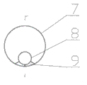
图8为应用本发明形成的第三种抽水和回灌两用井管的侧视图;Fig. 8 is the side view of the third pumping and recharging dual-purpose well pipe formed by applying the present invention;
图9为图7的剖面图;Fig. 9 is a sectional view of Fig. 7;
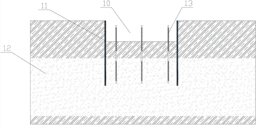
图10为本发明应用的示意图。Fig. 10 is a schematic diagram of the application of the present invention.
图中:1、抽水井的止水段,2、抽水井的滤水段,3、抽水井的沉淀段,4、回灌井的止水段,5、回灌井的滤水段,6、回灌井的沉淀段,7、井管,8、灌水管,9、焊接支撑铁片,10、基坑,11、止水帷幕,12、含水层,13、抽水和回灌两用井管。In the figure: 1, the water stop section of the pumping well, 2, the water filtering section of the pumping well, 3, the sedimentation section of the pumping well, 4, the water stopping section of the recharge well, 5, the water filter section of the recharge well, 6 , Sedimentation section of recharge well, 7. Well pipe, 8. Irrigation pipe, 9. Welded supporting iron sheet, 10. Foundation pit, 11. Water-stop curtain, 12. Aquifer, 13. Dual-purpose well for pumping and recharging Tube.
具体实施方式Detailed ways
为能进一步了解本发明的发明内容、特点及功效,兹例举以下实施例,并配合附图详细说明如下:In order to further understand the invention content, characteristics and effects of the present invention, the following examples are given, and detailed descriptions are as follows in conjunction with the accompanying drawings:
请参阅图1~图10,一种井管内同时抽水和回灌的沉降控制方法,包括以下步骤:Please refer to Figures 1 to 10, a settlement control method for simultaneous pumping and recharging in a well pipe, including the following steps:
一)根据基坑10的深度、止水帷幕11的深度和含水层12的分布状况,分析确定在同一井孔位上抽水井的滤水段2的位置和回灌井的滤水段6的位置;1) According to the depth of the foundation pit 10, the depth of the water-stop curtain 11 and the distribution of the aquifer 12, analyze and determine the position of the
二)设计确定抽水井的止水段1、滤水段2和沉淀段3,设计确定回灌井的止水段4、滤水段5和沉淀段6;2) Design and determine the water stop section 1,
三)根据井管结构,确定井孔钻孔直径和深度;3) Determine the borehole diameter and depth according to the well pipe structure;
四)采用钻机钻井孔到井管管底深度位置;4) Use a drilling rig to drill the wellbore to the depth position of the bottom of the well pipe;
五)在同一井孔位上完成回灌井和降水井的施工,形成抽水和回灌两用井管13,回灌井的灌水管8通过焊接支撑铁片9固定在降水井的井管7内,回灌井的灌水管8上端与降水井的井管7上端平齐。5) Complete the construction of the recharge well and the dewatering well on the same well hole position, forming a dual-purpose well pipe 13 for pumping and recharging, and the
请参阅图1~图3,图1~图3示出了上述抽水和回灌两用井管的第一种结构,所述回灌井的井管的直径小于所述降水井的井管的直径,所述回灌井的灌水管8的直径与回灌井的井管直径相同,所述回灌井的灌水管8与所述回灌井的井管相互固接。Please refer to Fig. 1~Fig. 3, Fig. 1~Fig. 3 has shown the first kind of structure of above-mentioned pumping and recharging dual-purpose well pipe, and the diameter of the well pipe of described reinjection well is smaller than the well pipe of described dewatering well Diameter, the diameter of the
请参阅图4~图6,图4~图6示出了上述抽水和回灌两用井管的第二种结构,所述回灌井的井管的直径与所述降水井的井管的直径相同,所述回灌井的灌水管8的直径小于所述回灌井的井管直径,所述回灌井的灌水管8的下端延伸至所述回灌井的滤水段上端。Please refer to Fig. 4~Fig. 6, Fig. 4~Fig. 6 have shown the second kind of structure of above-mentioned pumping and recharging dual-purpose well pipe, the diameter of the well pipe of described reinjection well and the well pipe of described dewatering well The diameters are the same, the diameter of the
请参阅图7~图9,图7~图9示出了上述抽水和回灌两用井管的第三种结构,所述回灌井的井管的直径与所述降水井的井管的直径相同,所述回灌井的灌水管8的直径小于所述回灌井的井管直径,所述回灌井的灌水管8的下端延伸至所述回灌井的止水段上端。Please refer to Fig. 7~Fig. 9, Fig. 7~Fig. 9 have shown the third kind of structure of above-mentioned pumping and recharging dual-purpose well pipe, the diameter of the well pipe of described reinjection well and the well pipe of described dewatering well The diameters are the same, the diameter of the
成井的具体工序为:The specific process of forming a well is:
(a)在预制井底上放置井管,缓缓下放,当管口与井口相差200mm时,接上节井管。吊放井管要垂直,并保持在井孔中心,为防止雨水泥砂或异物流入井中,井管高出地面不小于200mm,并加盖临时保护。井管滤水段采用无砂砼滤管或带滤孔的铁管,井管非滤水管采用无砂砼滤管或不带滤孔的铁管。(a) Place the well pipe on the prefabricated well bottom and lower it slowly. When the difference between the pipe head and the well head is 200mm, connect the well pipe. The hoisting well pipe should be vertical and kept in the center of the well hole. In order to prevent rain cement sand or foreign matter from flowing into the well, the well pipe should be no less than 200mm above the ground and covered temporarily for protection. The filter section of the well pipe adopts sand-free concrete filter pipe or iron pipe with filter holes, and the non-filter pipe of the well pipe adopts sand-free concrete filter pipe or iron pipe without filter holes.
(b)井管下入后立即填入滤料和粘土球。滤料填入滤水段和沉淀段位置,粘土球填入止水段位置。滤料和粘土球沿井孔四周均匀填入,宜保持连续,将泥浆挤出井孔。填滤料和粘土球时,随填随测滤料和粘土球填入高度,当填入量与理论计算量不一致时,及时查找原因进行补填或换填。(b) Fill the filter material and clay balls immediately after the well pipe is run in. The filter material is filled into the position of the filter water section and the sedimentation section, and the clay ball is filled into the position of the water stop section. The filter material and clay balls should be filled evenly along the periphery of the wellbore, and should be kept continuous to squeeze the mud out of the wellbore. When filling the filter material and clay balls, measure the filling height of the filter material and clay balls while filling. When the filling amount is inconsistent with the theoretical calculation amount, find out the reason in time and fill or replace it.
(c)填滤料和粘土球后应立即进行洗井,以免时间过长,护壁泥皮逐渐老化,难以破坏,影响渗水和灌水效果。冲洗时,采用下泵试抽洗井,用潜水泵反复进行抽洗,直至水清砂净。(c) The well should be washed immediately after filling the filter material and clay balls, so as not to take too long, and the wall mud skin will gradually age and be difficult to damage, which will affect the water seepage and irrigation effects. When flushing, use the lower pump to test pumping and washing the well, and use the submersible pump to repeatedly pump and wash until the water is clear of sand.
此后,进行抽水,将抽水的水流放在外置沉淀池内。待沉淀池内水澄清后,将清水用水泵抽取灌入井管内的回灌管。Thereafter, water is pumped, and the water flow of the pumped water is placed in an external settling tank. After the water in the sedimentation tank is clarified, the clean water is pumped with a water pump and poured into the recharge pipe in the well pipe.
本发明针对深厚含水层内基坑降水的渗流场特点,在降水位置布置抽水滤水段,在补水位置设置回灌滤水段,将降水和回灌在一个井管内完成,施工简便、造价低廉、回灌高效,起到控制地面沉降和地下水资源保护的目的。According to the characteristics of the seepage field of foundation pit dewatering in the deep aquifer, the present invention arranges a pumping and filtering section at the dewatering position, and sets a refilling and filtering section at the water supply position, and completes dewatering and recharging in one well pipe, which is simple in construction and low in cost , Recharging is efficient, and it can control land subsidence and protect groundwater resources.
本发明的基本原理是:在悬挂式止水帷幕内降水,渗流场的特征是含水层下部或中部的水流向含水层上部,即基坑底井管内降水来自含水层内自下而上的供水补给,基坑内或基坑附近含水层又获得基坑外含水层供水补给,形成由外而内、由下而上的渗流场渗流路径。基于这样的渗流场特点,将降水井管竖向延长至含水层的供水补给位置,在该位置设置井管回灌滤水段,即在降水位置布置抽水滤水段,在补水位置设置回灌滤水段。在降水井内设置回灌通道将抽出去的水经沉淀澄清后回灌至回灌滤水段,将降水和回灌在一个井管内完成,降低含水层由基坑外向基坑内补给量,减少地面沉降。The basic principle of the present invention is: precipitation in the suspended water-stop curtain, the feature of the seepage field is that the water in the lower or middle part of the aquifer flows to the upper part of the aquifer, that is, the precipitation in the well pipe at the bottom of the foundation pit comes from the bottom-up water supply in the aquifer Recharge, the aquifer in or near the foundation pit is supplied with water from the aquifer outside the foundation pit, forming a seepage path from the outside to the inside and from the bottom to the top. Based on the characteristics of the seepage field, the precipitation well pipe is vertically extended to the water supply position of the aquifer, and the well pipe refilling and filtering section is set at this position, that is, the pumping and filtering section is arranged at the precipitation position, and the recharging section is set at the water supply position. filter section. Set up a recharge channel in the dewatering well to recharge the pumped water to the recharge filter section after sedimentation and clarification, complete the dewatering and recharge in one well pipe, reduce the recharge of the aquifer from the outside of the foundation pit to the inside of the foundation pit, and reduce the ground settlement.
本发明基于基坑降水的渗流场特征,整合现有成熟的降水井技术和回灌井技术,通过在降水井内设置回灌通道使二井合一,既可减少地面沉降又可保护地下水资源,同时该技术具有施工简便、造价低廉、回灌高效的优点。Based on the seepage field characteristics of foundation pit dewatering, the present invention integrates the existing mature dewatering well technology and reinjection well technology, and integrates the two wells into one by setting a recharge channel in the dewatering well, which can not only reduce ground subsidence but also protect groundwater resources, and at the same time This technology has the advantages of simple construction, low cost and high recharge efficiency.
本发明的应用实例1:Application example 1 of the present invention:
请参见图10,某地铁车站基坑工程呈矩形长160m,宽22.1m,采取明挖法施工,支护结构为地下连续墙和内支撑,基坑挖深25.63m。地下连续墙兼作止水帷幕,墙厚1m,墙深45m。承压含水层顶板埋深为30m,含水层厚达21m。基坑降水井滤水段进入承压含水层,止水帷幕未截断承压含水层,采用常规降水方法会导致承压含水层大量抽水和地面沉降难以控制。采用本发明方法使地面沉降得到有效控制。Please refer to Figure 10. The foundation pit project of a certain subway station is rectangular in length, 160m long, and 22.1m wide. The underground diaphragm wall doubles as a water-stop curtain, with a thickness of 1m and a depth of 45m. The roof of the confined aquifer is buried at a depth of 30m, and the aquifer is as thick as 21m. The water filtration section of the foundation pit dewatering well enters the confined aquifer, and the water-stop curtain does not cut off the confined aquifer. Using conventional dewatering methods will lead to a large amount of water pumping from the confined aquifer and difficult to control land subsidence. The ground subsidence is effectively controlled by adopting the method of the invention.
根据计算分析,确定井管抽水部分长35m,其中从管口向下01m为止水段、134m为抽水滤水段、34~35m为沉淀段;确定灌水部分长20m,从管口向下3543m为止水段、4354m为回灌滤水段、5455m为沉淀段。抽水井管直径与灌水管直径都为273mm,长度为55m。灌水通道管直径为100mm,长度为35m,灌水通道管焊附在井管壁上。井管钻孔直径为600mm。钻孔深为55m。According to the calculation and analysis, it is determined that the pumping part of the well pipe is 35m long, of which the water-stop section is 01m downward from the nozzle, the pumping and filtering section is 134m, and the sedimentation section is 34-35m; the irrigation part is determined to be 20m long, and it is 3543m from the nozzle In the water section, 4354m is the recharge and filtration section, and 5455m is the sedimentation section. The diameter of the pumping well pipe and the irrigation pipe are both 273mm and 55m in length. The irrigation channel pipe has a diameter of 100mm and a length of 35m, and the irrigation channel pipe is welded to the wall of the well pipe. Well pipe drilling diameter is 600mm. The drilling depth is 55m.
基坑内共布置抽水和回灌两用井管共20口,基坑外设置4个沉淀池,每5口井共用一个沉淀池。每个井管内放置一个抽水泵,抽出的水排入沉淀池,沉淀池内澄清后的水再由水泵抽起灌入到井管内的灌水通道管,进而回灌入含水层。A total of 20 dual-purpose well pipes for pumping and recharging are arranged in the foundation pit, and 4 sedimentation tanks are set outside the foundation pit, and every 5 wells share a sedimentation tank. A suction pump is placed in each well pipe, and the pumped water is discharged into the sedimentation tank, and the clarified water in the sedimentation tank is pumped by the water pump and poured into the irrigation channel pipe in the well pipe, and then refilled into the aquifer.
经现场监测,约3/4基坑涌水量回灌入地下含水层,降水6个月,地面沉降控制在15mm内,达到了工程预期效果。According to on-site monitoring, about 3/4 of the water inflow from the foundation pit was refilled into the underground aquifer. After 6 months of precipitation, the ground subsidence was controlled within 15mm, which achieved the expected effect of the project.
本发明的应用实例2:Application example 2 of the present invention:
某大厦基坑工程开挖面积约1万m2,开挖深度约14.2m,基坑支护工程采用两道临时钢筋混凝土水平支撑系统;止水帷幕为单排Φ650900三轴水泥搅拌桩,桩长23m;采取明挖法施工。基坑底下覆承压含水层,其层顶埋深约为30.5m,含水层厚度33m左右,承压水水位埋深约为1.50~1.90m,不满足抗突涌稳定验算,工程中需布置降压井。采用常规降水方法会导致承压含水层大量抽水和地面沉降难以控制,采用本发明方法将降压井制作成为降压和回灌两用的井管,降压和回灌同时进行,使地面沉降得到有效控制。The excavation area of the foundation pit project of a building is about 10,000 m 2 , and the excavation depth is about 14.2m. The foundation pit support project adopts two temporary reinforced concrete horizontal support systems; The length is 23m; the open cut method is adopted for construction. Underneath the foundation pit is a confined aquifer, the buried depth of the top layer is about 30.5m, the thickness of the aquifer is about 33m, and the buried depth of the confined water level is about 1.50-1.90m. Step-down well. Adopting the conventional dewatering method will lead to a large amount of water pumping in the confined aquifer and difficult to control the land subsidence. Using the method of the present invention, the depressurization well is made into a dual-purpose well pipe for depressurization and recharge, and the depressurization and recharge are carried out at the same time, so that the ground subsidence be effectively controlled.
根据计算分析,确定降压回灌两用井管抽水部分长38m,其中从管口向下031m为止水段、3137m为抽水滤水段、3738m为沉淀段;确定降压回灌两用井管灌水部分长16m,从管口向下3843m为止水段、4353m为回灌滤水段、5354m为沉淀段。抽水井管直径与灌水管直径都为273mm,长度为54m。灌水通道管直径为100mm,长度为43m,灌水通道管焊附在井管壁上。井管钻孔直径为600mm。钻孔深为54m。According to the calculation and analysis, it is determined that the pumping part of the dual-purpose well pipe for depressurization and recharge is 38m long, of which 031m is the cut-off section from the nozzle, 3137m is the pumping and filtering section, and 3738m is the sedimentation section; The irrigation section is 16m long, 3843m downward from the nozzle, 4353m for the refilling and filtering section, and 5354m for the sedimentation section. The diameter of the pumping well pipe and the irrigation pipe are both 273mm and 54m in length. The irrigation channel pipe has a diameter of 100mm and a length of 43m, and the irrigation channel pipe is welded to the wall of the well pipe. Well pipe drilling diameter is 600mm. The drilling depth is 54m.
基坑内将降压井管只作为本发明的抽水和回灌两用井管,共布置抽水和回灌两用井管共28口,基坑外设置7个沉淀池,每4口井共用一个沉淀池。每个井管内放置一个抽水泵,抽出的水排入沉淀池,沉淀池内澄清后的水再由水泵抽起灌入到井管内的灌水通道管,进而回灌入承压含水层。In the foundation pit, the pressure-reducing well pipe is only used as the pumping and recharging dual-purpose well pipe of the present invention, a total of 28 pumping and recharging dual-purpose well pipes are arranged, and 7 sedimentation tanks are set outside the foundation pit, and every 4 wells share one Sedimentation tank. A suction pump is placed in each well pipe, and the pumped water is discharged into the sedimentation tank, and the clarified water in the sedimentation tank is pumped by the water pump and poured into the irrigation channel pipe in the well pipe, and then refilled into the confined aquifer.
经现场监测,约1/2降压抽水量回灌入地下含水层,降压3个月,地面沉降控制在20mm内,达到了工程预期效果。According to on-site monitoring, about 1/2 of the depressurized pumped water was recharged into the underground aquifer. After 3 months of depressurization, the land subsidence was controlled within 20mm, which achieved the expected effect of the project.
尽管上面结合附图对本发明的优选实施例进行了描述,但是本发明并不局限于上述的具体实施方式,上述的具体实施方式仅仅是示意性的,并不是限制性的,本领域的普通技术人员在本发明的启示下,在不脱离本发明宗旨和权利要求所保护的范围情况下,还可以作出很多形式,这些均属于本发明的保护范围之内。Although the preferred embodiments of the present invention have been described above in conjunction with the accompanying drawings, the present invention is not limited to the above-mentioned specific embodiments. The above-mentioned specific embodiments are only illustrative and not restrictive. Those of ordinary skill in the art Under the enlightenment of the present invention, people can also make many forms without departing from the purpose of the present invention and the scope of protection of the claims, and these all belong to the protection scope of the present invention.
Claims (4)
Priority Applications (1)
| Application Number | Priority Date | Filing Date | Title |
|---|---|---|---|
| CN2012105432534A CN103088836A (en) | 2012-12-15 | 2012-12-15 | Sedimentation control method for pumping water and performing reinjection in well casing simultaneously |
Applications Claiming Priority (1)
| Application Number | Priority Date | Filing Date | Title |
|---|---|---|---|
| CN2012105432534A CN103088836A (en) | 2012-12-15 | 2012-12-15 | Sedimentation control method for pumping water and performing reinjection in well casing simultaneously |
Publications (1)
| Publication Number | Publication Date |
|---|---|
| CN103088836A true CN103088836A (en) | 2013-05-08 |
Family
ID=48201927
Family Applications (1)
| Application Number | Title | Priority Date | Filing Date |
|---|---|---|---|
| CN2012105432534A Pending CN103088836A (en) | 2012-12-15 | 2012-12-15 | Sedimentation control method for pumping water and performing reinjection in well casing simultaneously |
Country Status (1)
| Country | Link |
|---|---|
| CN (1) | CN103088836A (en) |
Cited By (10)
| Publication number | Priority date | Publication date | Assignee | Title |
|---|---|---|---|---|
| CN103306683A (en) * | 2013-06-18 | 2013-09-18 | 中铁隧道集团有限公司 | Construction method for comprehensive precipitation in hole in deep-buried tunnel excavation process |
| CN103510501A (en) * | 2013-10-23 | 2014-01-15 | 天津大学 | Method for preventing blocking and water gushing in recharge well |
| CN104594327A (en) * | 2015-01-13 | 2015-05-06 | 济南轨道交通集团有限公司 | Water settling, spring protection and recharging integrated device for foundation pit engineering |
| CN104831742A (en) * | 2015-04-15 | 2015-08-12 | 中国建筑第八工程局有限公司 | Foundation pit dewatering method with two adjacent micro confined aquifers not separated by water-proof layer |
| CN105155561A (en) * | 2015-09-21 | 2015-12-16 | 中铁上海工程局集团有限公司 | Relief well arrangement optimization method based on BIM technology |
| CN108277807A (en) * | 2018-04-09 | 2018-07-13 | 浙江乔兴建设集团有限公司 | Deep basal pit artesian water is prominent to gush decompression control water-bound |
| CN110485510A (en) * | 2019-09-26 | 2019-11-22 | 上海勘察设计研究院(集团)有限公司 | A kind of forced recharge well construction of gradation and its application method |
| CN114486683A (en) * | 2022-02-16 | 2022-05-13 | 上海工程技术大学 | Test device for simulating pumping in foundation pit and recharging underground water outside foundation pit |
| CN115305901A (en) * | 2022-08-16 | 2022-11-08 | 中交第四公路工程局有限公司 | Directional recharge and emergency pumping well |
| CN119287953A (en) * | 2024-12-12 | 2025-01-10 | 沈阳帝铂建筑工程有限公司 | An integrated well structure and construction method for bottom water intake and top water recharging |
Citations (7)
| Publication number | Priority date | Publication date | Assignee | Title |
|---|---|---|---|---|
| JP2002121743A (en) * | 2000-10-12 | 2002-04-26 | Nisshin Kenko Kk | Ground water lowering method and ground water lowering device used for the method |
| JP2007285090A (en) * | 2006-04-20 | 2007-11-01 | Takenaka Komuten Co Ltd | Underground water level lowering method for excavated ground, and filling/pumping well for use in the method |
| CN201367577Y (en) * | 2008-12-30 | 2009-12-23 | 上海长凯岩土工程有限公司 | Groundwater recharge well |
| CN102383412A (en) * | 2010-08-27 | 2012-03-21 | 中铁二十二局集团第三工程有限公司 | Construction method by adopting dewatering and water recharging to control sedimentation surrounding deep foundation pit |
| JP2012087501A (en) * | 2010-10-18 | 2012-05-10 | Ohbayashi Corp | Well, well construction method, groundwater level lowering method, method for constructing earth retaining wall, and sheet pile |
| CN102505677A (en) * | 2011-09-29 | 2012-06-20 | 上海隧道工程股份有限公司 | Method for controlling sedimentation through recharging engineering groundwater |
| CN102635122A (en) * | 2012-04-10 | 2012-08-15 | 上海广联建设发展有限公司 | Dewatering-recharging integrated device and process for foundation pit engineering |
-
2012
- 2012-12-15 CN CN2012105432534A patent/CN103088836A/en active Pending
Patent Citations (7)
| Publication number | Priority date | Publication date | Assignee | Title |
|---|---|---|---|---|
| JP2002121743A (en) * | 2000-10-12 | 2002-04-26 | Nisshin Kenko Kk | Ground water lowering method and ground water lowering device used for the method |
| JP2007285090A (en) * | 2006-04-20 | 2007-11-01 | Takenaka Komuten Co Ltd | Underground water level lowering method for excavated ground, and filling/pumping well for use in the method |
| CN201367577Y (en) * | 2008-12-30 | 2009-12-23 | 上海长凯岩土工程有限公司 | Groundwater recharge well |
| CN102383412A (en) * | 2010-08-27 | 2012-03-21 | 中铁二十二局集团第三工程有限公司 | Construction method by adopting dewatering and water recharging to control sedimentation surrounding deep foundation pit |
| JP2012087501A (en) * | 2010-10-18 | 2012-05-10 | Ohbayashi Corp | Well, well construction method, groundwater level lowering method, method for constructing earth retaining wall, and sheet pile |
| CN102505677A (en) * | 2011-09-29 | 2012-06-20 | 上海隧道工程股份有限公司 | Method for controlling sedimentation through recharging engineering groundwater |
| CN102635122A (en) * | 2012-04-10 | 2012-08-15 | 上海广联建设发展有限公司 | Dewatering-recharging integrated device and process for foundation pit engineering |
Cited By (17)
| Publication number | Priority date | Publication date | Assignee | Title |
|---|---|---|---|---|
| CN103306683A (en) * | 2013-06-18 | 2013-09-18 | 中铁隧道集团有限公司 | Construction method for comprehensive precipitation in hole in deep-buried tunnel excavation process |
| CN103510501A (en) * | 2013-10-23 | 2014-01-15 | 天津大学 | Method for preventing blocking and water gushing in recharge well |
| CN103510501B (en) * | 2013-10-23 | 2015-04-29 | 天津大学 | Method for preventing blocking and water gushing in recharge well |
| CN104594327A (en) * | 2015-01-13 | 2015-05-06 | 济南轨道交通集团有限公司 | Water settling, spring protection and recharging integrated device for foundation pit engineering |
| CN104594327B (en) * | 2015-01-13 | 2016-06-15 | 济南轨道交通集团有限公司 | A kind of Ground Water Pumping during Excavation Bao Quan recharges integrated apparatus |
| CN104831742A (en) * | 2015-04-15 | 2015-08-12 | 中国建筑第八工程局有限公司 | Foundation pit dewatering method with two adjacent micro confined aquifers not separated by water-proof layer |
| CN105155561A (en) * | 2015-09-21 | 2015-12-16 | 中铁上海工程局集团有限公司 | Relief well arrangement optimization method based on BIM technology |
| CN105155561B (en) * | 2015-09-21 | 2017-06-30 | 中铁上海工程局集团有限公司 | Pressure reduction well optimizing method for disposing based on BIM technology |
| CN108277807A (en) * | 2018-04-09 | 2018-07-13 | 浙江乔兴建设集团有限公司 | Deep basal pit artesian water is prominent to gush decompression control water-bound |
| CN110485510A (en) * | 2019-09-26 | 2019-11-22 | 上海勘察设计研究院(集团)有限公司 | A kind of forced recharge well construction of gradation and its application method |
| CN110485510B (en) * | 2019-09-26 | 2024-03-19 | 上海勘察设计研究院(集团)股份有限公司 | Fractional press-in type recharging well structure and application method thereof |
| CN114486683A (en) * | 2022-02-16 | 2022-05-13 | 上海工程技术大学 | Test device for simulating pumping in foundation pit and recharging underground water outside foundation pit |
| CN114486683B (en) * | 2022-02-16 | 2023-07-21 | 上海工程技术大学 | A test device for simulating pumping in foundation pits and recharging groundwater outside foundation pits |
| CN115305901A (en) * | 2022-08-16 | 2022-11-08 | 中交第四公路工程局有限公司 | Directional recharge and emergency pumping well |
| CN115305901B (en) * | 2022-08-16 | 2024-05-28 | 中交第四公路工程局有限公司 | Directional recharging and emergency pumping well |
| CN119287953A (en) * | 2024-12-12 | 2025-01-10 | 沈阳帝铂建筑工程有限公司 | An integrated well structure and construction method for bottom water intake and top water recharging |
| CN119287953B (en) * | 2024-12-12 | 2025-04-15 | 沈阳帝铂建筑工程有限公司 | Integrated well structure with water taken from lower part and recharging from upper part and construction method |
Similar Documents
| Publication | Publication Date | Title |
|---|---|---|
| CN103088836A (en) | Sedimentation control method for pumping water and performing reinjection in well casing simultaneously | |
| CN102635402A (en) | Siphon drainage method for tunnel wall water seepage disposal by using dipping borehole | |
| CN105040775B (en) | Deep layer pressure-bearing artesian well plugging system and method | |
| LU500273B1 (en) | New comprehensive dewatering and drainage method and drainage device for mudstone subway station | |
| CN102383437B (en) | Well point positioned pumping tubular well and well point positioned pumping method | |
| CN111827328A (en) | Subway deep foundation pit well point dewatering system and construction method thereof | |
| CN102535490A (en) | Method for dewatering foundation pit by using bored cast-in-place pile | |
| CN102995647B (en) | A Groundwater Control Method for Pile Hole Grouting and Seepage Isolation | |
| CN114718101A (en) | Seepage interception structure of tailing pond of seepage interception wall combined dewatering well and construction method thereof | |
| CN105603892B (en) | A kind of construction method of water staple water system for Railway Bed Slope | |
| CN203066092U (en) | Pumping and recharging dual-purpose well casing | |
| CN115142451A (en) | Construction method of dynamic balance control of water level inside and outside deep foundation pit Water level stabilization device | |
| CN216640547U (en) | A drainage pressure reduction and anti-floating system suitable for weakly permeable soft soil layers | |
| CN111456055A (en) | Foundation pit dewatering construction method | |
| CN104389634A (en) | Mine vertical shaft/sieve shaft well wall structure and controllable dewatering method thereof | |
| CN114250801A (en) | Pipe well and light well point combined dewatering construction method | |
| CN106088123A (en) | A kind of sand geology steel tube well fall water level device and construction method thereof | |
| CN116290047B (en) | Automatic-monitoring deep foundation pit transverse connection type net-shaped precipitation construction method | |
| CN204311464U (en) | A kind of foundation pit dewatering constructing structure | |
| CN103669333B (en) | It is easy to the friction pile of vacuum-dewatering | |
| CN203891785U (en) | Special joint pipe assembly for throwing of gravels in pipe of hydrogeological water well | |
| CN202187360U (en) | A Well Point Positioning Pumping Tube Well | |
| CN104060636B (en) | Pressure release anti-float method during high water level regional architecture foundation construction and device | |
| CN114045850A (en) | Construction method for replacing waterproof curtain by combination of light well point and pneumatic dewatering | |
| CN113431628A (en) | Three-dimensional dewatering method for quicksand stratum |
Legal Events
| Date | Code | Title | Description |
|---|---|---|---|
| C06 | Publication | ||
| PB01 | Publication | ||
| C10 | Entry into substantive examination | ||
| SE01 | Entry into force of request for substantive examination | ||
| C02 | Deemed withdrawal of patent application after publication (patent law 2001) | ||
| WD01 | Invention patent application deemed withdrawn after publication |
Application publication date: 20130508 |