CN103075991A - Measuring device for super-large type gear and measuring method thereof - Google Patents
Measuring device for super-large type gear and measuring method thereof Download PDFInfo
- Publication number
- CN103075991A CN103075991A CN2012105687586A CN201210568758A CN103075991A CN 103075991 A CN103075991 A CN 103075991A CN 2012105687586 A CN2012105687586 A CN 2012105687586A CN 201210568758 A CN201210568758 A CN 201210568758A CN 103075991 A CN103075991 A CN 103075991A
- Authority
- CN
- China
- Prior art keywords
- gear
- measuring
- super
- measuring staff
- point
- Prior art date
- Legal status (The legal status is an assumption and is not a legal conclusion. Google has not performed a legal analysis and makes no representation as to the accuracy of the status listed.)
- Granted
Links
Images
Abstract
The invention relates to a measuring device for a super-large type gear and a measuring method thereof and aims to provide a measuring device and a measuring method without the need of driving the super-large type gear. The measuring device for the super-large type gear comprises a workbench, a measuring instrument and a laser tracker which are mutually independent, wherein the measuring instrument comprises a centering mechanism, a rotary arm rotating by taking the center of the centering mechanism as a rotating shaft is arranged at the side of the centering mechanism, and the tail end of the rotary arm is provided with a measuring head which can be moved linearly in a horizontal plane and also can be moved in the vertical direction. The measuring device and the measuring method disclosed by the invention have the beneficial effects of no influence from the large size and heavy weight of the gear, convenience in measurement and high precision, and can be applied for measuring the super-large type gear.
Description
Technical field
The present invention relates to a kind of measurement mechanism and measuring method thereof of super-huge gear.
Background technology
Gear is the important foundation parts in the industrial transmission, and the gear that it has been generally acknowledged that diameter 500-3000mm is large gear, and diameter is super-huge gear greater than 3000mm's.Because the Heavy machinery industries such as metallurgy, mine, shipbuilding, lifting, wind-power electricity generation improve constantly the large gear request for utilization, its manufacture level obtains fast lifting, and is also more and more urgent to the demand of its accuracy detection.Yet, being subjected to the impact of the factors such as physical dimension is large, quality is large, measurement large-scale and super-huge gear is a difficult problem in gear testing field always.
The measuring method of existing large gear mainly contains:
1. on-machine measurement
On-machine measurement is to use more a kind of measuring method.Its basic platform is numerical control machine tool, because after Gear Processing is finished, do not need gear reorientated and be installed, therefore, easy to use, efficient advantages of higher that the method has, its shortcoming are to get rid of fully lathe self precision to the impact of measurement result.
2. overhead is measured
The overhead measurement is on machining tool or worktable, take certain parameter of tested gear as measuring basis, the overhead measuring instrument can be measured around tested gear, and advantage is not need to move tested gear, have easy to use, volume is little, low cost and other advantages.But because positioning requirements is high, and is difficult to accurately set up workpiece coordinate system and measures contacting between the coordinate system, so measuring accuracy still there is room for promotion.
3. large gear amount instrument
Large gear amount instrument is on the basis of middle pinion wheel amount instrument, the desk-top Special measuring instrument of developing according to the characteristics of large gear, its advantage is that measuring accuracy is high, efficient is high, function is strong, but it is high that shortcoming is instrument cost, and along with the increasing of measurement range, the manufacturing meeting of instrument is more difficult, it is generally acknowledged that can survey maximum outside diameter is that the large gear measuring center of 3000mm is near the manufacture level limit of present stage large gear amount instrument.
Super-huge gear is because of the physical dimension of its super large, and tens of tons the weight of weighing is above-mentioned the on-position measure methods such as machine or overhead measurement, substantially without feasible method except adopting.
Chinese patent notification number CN102022990A discloses a kind of large gear measuring instrument, described gear measurement machine is combined side by side by separate measurement mechanism and rotary table, and measurement mechanism is positioned at a side of rotary table, described rotary table is assemblied on the rotary table base by hydrostatic slideway supporting and hydrodynamic journal liquid polymers centering, and described rotary table drives by being installed in twin worm on the rotary table base gap gear train that disappears.This gear measurement machine is by the rotation of rotatable worktable driven wheel, thereby measures, and this mode is for super large physical dimension, tens of tons the super-huge gear of weighing, and the manufacturing of measuring instrument and the driving of gear are all extremely difficult, and efficient is low.
China Patent Publication No. CN101561349A discloses a kind of detection method and pick-up unit of large gear, described method adopts coordinate method, utilize whirligig to make tested gear rotation, and utilize measuring motion that the flank profil of tested gear is detected, the datum axis of tested gear and the relative position between the measuring motion change by laser tracker to be determined, then the data that this changing value and measuring motion gathered and the anglec of rotation data of whirligig are processed, thereby draw the geometric error of tested gear, described device comprises be used to the measuring motion of laying tested gear and is used for determining the datum axis of tested gear and the laser tracker that the relative position between the measuring motion changes.There are the problems referred to above equally in the detection method of this large gear and pick-up unit.
Summary of the invention
The object of the present invention is to provide measurement mechanism and the measuring method of the super-huge gear of a kind of not demand motive, with solve exist in the background technology for the super large physical dimension, tens of tons super-huge gear weighs, the manufacturing of measuring instrument and the driving of gear are all extremely difficult, and service efficiency is lower.
To achieve these goals, the invention provides a kind of measurement mechanism, its technical scheme is: a kind of measurement mechanism of super-huge gear, comprise separate worktable, measuring instrument and laser tracker, described measuring instrument comprises centering machine, it is the spiral arm of turning axle rotation that described centering machine side direction is provided with take its center, the spiral arm end both be provided with can be in surface level traveling priority and the gauge head that can move at vertical direction.The design philosophy of this technical scheme is: gear is positioned on the worktable (or gear cutting machine worktable), utilize centering machine to be arranged to the rotation center of measuring instrument and Gear axis coaxial, utilize afterwards laser tracker to set up the coordinate system of tested gear and measuring instrument is felt relieved, use measuring instrument to measure, then by reading the data of feeding back on the measuring instrument measured parameter is calculated, this measurement mechanism is simple, not affected by volume, the weight factor of gear, it is convenient to measure, and precision is high.
As preferably, described centering machine comprises the chassis, and the upper surface center on chassis is provided with column, and described spiral arm is located at column radially and can column is the turning axle rotation.
As preferably, described chassis circumferentially to external radiation a plurality of identical sway braces are arranged.
As preferably, described a plurality of sway braces are circumferentially uniform the chassis.Above three for the design of gears with center pit, during use, sway brace support is felt relieved at the inwall of center pit.
As preferably, described centering machine comprises pivoting support, and the inner ring of pivoting support is adaptive with gear shaft and be fixedly connected with, and the outer ring of pivoting support is fixedly connected with spiral arm.This is for the design of gears with gear shaft, during use, is enclosed within on the gear shaft inner ring of pivoting support fixing in order to centering.
As preferably, described spiral arm is provided with the horizontal measuring staff that can move along the spiral arm length direction, and the outboard end of horizontal measuring staff is provided with upright arm, and upright arm is provided with the vertical measuring staff that can move along the upright arm length direction, and described gauge head is located at vertical measuring staff bottom.This is intended to make gauge head to move up with Vertical Square in the horizontal direction, could measure flank profil and the helix of the gear teeth like this.
As preferably, described horizontal measuring staff is provided with the horizon light gate sensor that its horizontal shift of record changes, and vertical measuring staff is provided with the vertical raster sensor that its perpendicular displacement of record changes.
As preferably, the below at described spiral arm middle part is fixed with support column, and support column is provided with the bevel gear kinematic pair that can drive spiral arm.This is intended to realize that spiral arm is rotatable.
As preferentially, described gauge head is the inductance sensor gauge head.
In addition, the present invention also provides the measuring method of above-mentioned measurement mechanism, and its technical scheme is: a kind of method that adopts above-mentioned measurement mechanism to measure super-huge gear may further comprise the steps:
Step 1: utilize laser tracker, set up reference plane and the datum axis of tested gear.Concrete grammar is:
(1) at first tested gear is placed on the worktable, if gear has center pit, then in the hole along at least five points of circumferencial direction sampling; If gear sprocket drive spindle, then on axle in the circumferential direction of the circle the sampling at least five points, data point with sampling becomes a circle according to least square fitting afterwards, then along bore or gear shaft axially, on several faces parallel with gear face, be taken to as stated above few five circles, the above a plurality of centers of circle that obtain are fitted to straight line, and this line is the rotation of gear, also as datum axis;
(2) after determining datum axis, on gear face, be taken to few five points, simulate a plane, the intersection point of face and axis of making even this moment, and cross this intersection point and do the plane vertical with axis, this plane is the reference plane of tested gear.Intersection point is as circular cylindrical coordinate σ
1The true origin of (r, θ, z), datum axis is Z axis, sets up polar coordinates in reference plane, with pole axis r and polar angle θ point is described;
Step 2: determine measurement range and adjust measurement mechanism to guarantee in measurement range, the satisfying measuring accuracy requirement.Concrete grammar is:
(1) determined in the situation of rotation of tested gear in step 1, if gear has center pit, then with the sway brace support on the inwall of center pit; If the gear sprocket drive spindle then is enclosed within the pivoting support inner ring on the gear shaft fixing;
(2) play measuring point coordinate and measurement range by what the actual gear calculation of parameter went out gear, the position that utilizes laser tracker to read gauge head, by adjusting horizontal measuring staff, the distance that gauge head is moved to tested gear rotation has been the position of measuring point radius vector.Gauge head and Gear Contact were recorded as the starting point of actual measurement flank profil, and recorded its polar angle and radius vector this moment.Adjust horizontal measuring staff and while this moment and centered by the rotation of tested gear, rotate, drive gauge head and move to whole measuring point along the flank of tooth by playing a measuring point.By laser tracker 2 height is measured at this moment, and measured requirement by the position of adjusting measuring instrument until two point height differences satisfy, to guarantee the measuring accuracy of tooth profile error;
(3) fixing horizontal measuring staff and drive vertical measuring staff and carry out rectilinear motion, and record passes through coordinate a little, obtain its movement locus, adjust the relative position of vertical measuring staff and horizontal measuring staff, until make its movement locus reach the measurement requirement with respect to the depth of parallelism of datum axis, when measuring, can measure and evaluation in end face on the face of cylinder of reference circle on helix guaranteeing;
Step 3: concrete gear parameter is measured.Concrete grammar is:
(1) flank profil is measured: after adjusting whole device, from measuring point begin to measure, can be obtained the radius vector of point position this moment by horizontal measuring staff overall length and inductance sensor indicating value, cross measuring point and make the basic circle tangent line, make it satisfy the flank profil deviation in transverse plane and perpendicular to the condition of involute profile evaluation, can obtain tangential length by base radius and measuring point radius vector afterwards, and can try to achieve the length at tangent line and theoretical involute urve intersection point place, the difference of tangential length and length is the flank profil deviation at measuring point place;
(2) helix error measure: regulate horizontal measuring staff, so that the inductance sensor gauge head is on the face of cylinder of gear compound graduation circle, then fixing horizontal measuring staff, driving vertical measuring staff moves in the facewidth working range of actual gear along the flank of tooth, in this measuring process, the movement locus of record inductance sensor gauge head, the variation of record inductance sensor indicating value on the way, and be scaled the amount of end face basic circle on tangential, be spiral deviation on the way.
The measurement mechanism of the super-huge gear of the present invention and the beneficial effect of measuring method thereof are: be not subjected to the impact that gear volume is large, weight is large, measurement is convenient, precision is high.
Description of drawings
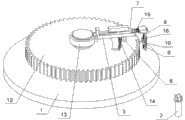
Fig. 1 is the structural representation of the measurement mechanism of super-huge gear among the embodiment 1;
Fig. 2 is the structural representation of the measurement mechanism of super-huge gear among the embodiment 2;
Fig. 3 is the geometric representation of practical tooth line.
Number in the figure is respectively: 1. worktable 2. laser trackers 3. chassis 4. columns, 5. spiral arms, 6. support columns, 7. horizontal measuring staff 8. upright arms 9. vertical measuring staff 10. inductance sensor gauge heads 11. sway braces 12. gears 13. pivoting supports 14. bevel gear kinematic pairs 15. horizon light gate sensors 16. vertical raster sensors.
Embodiment
Also by reference to the accompanying drawings technical scheme of the present invention is further described specifically below by embodiment.
Embodiment 1:
A kind of measurement mechanism of super-huge gear, as shown in Figure 1, this kind measurement mechanism is fit to have the super-huge gear of center pit, this measurement mechanism comprises separate worktable 1, measuring instrument and laser tracker 2, described measuring instrument comprises chassis 3, the circumferential of described chassis 3 has a plurality of identical circumferential uniform sway braces 11 to external radiation, 3 upper surface centers, chassis are connected with column 4, column 4 sidewalls radially be provided with the spiral arm 5 that can rotate take column 4 as turning axle, the below at described spiral arm 5 middle parts is fixed with support column 6, be provided with bevel gear kinematic pair 14 between support column 6 and the worktable 1, on the tooth bar bottom surface of bevel gear kinematic pair 14 magnet is housed, tooth bar can be adsorbed on the worktable 1 and maintain static, the drive motor of this kinematic pair is located in the support column, described spiral arm 5 is provided with horizontal measuring staff 7, described horizontal measuring staff 7 is driven by regulating device (for example hydraulic cylinder) horizontal measuring staff 7 can be moved along the spiral arm length direction, described horizontal measuring staff 7 is provided with the horizon light gate sensor 15 that its horizontal shift of record changes, the outboard end of horizontal measuring staff 7 is provided with upright arm 8, upright arm 8 is provided with vertical measuring staff 9, vertical measuring staff 9 is provided with the vertical raster sensor 16 that its perpendicular displacement of record changes, described vertical measuring staff 9 is driven by regulating device vertical measuring staff 9 can be moved along upright arm 8 length directions, and described vertical measuring staff 9 bottoms are provided with inductance sensor gauge head 10.
Adopt above-mentioned measurement mechanism to measure the method for super-huge gear, may further comprise the steps:
Step 1: utilize laser tracker 2, set up reference plane and the datum axis of tested gear 12.Concrete grammar is:
The tested gear 12 that (1) at first will have a center pit is placed on the worktable 1, then in the hole along at least five points of circumferencial direction sampling, data point with sampling becomes a circle according to least square fitting afterwards, then along gear 12 endoporus or gear shaft axially, on several faces parallel with gear 12 end faces, be taken to as stated above few three circles, the above a plurality of centers of circle that obtain are fitted to straight line, and this line is the rotation of gear 12, also as datum axis;
(2) after determining datum axis, on gear 12 end faces, be taken to few five points, simulate a plane, the intersection point of face and axis of making even this moment, and cross this intersection point and do the plane vertical with axis, this plane is the reference plane of tested gear 12.Intersection point is as circular cylindrical coordinate σ
1The true origin of (r, θ, z), datum axis is Z axis, sets up polar coordinates in reference plane, with pole axis r and polar angle θ point is described;
Step 2: determine measurement range and adjust measurement mechanism to guarantee in measurement range, the satisfying measuring accuracy requirement.Concrete grammar is:
(1) determined in the situation of rotation of tested gear 12 in step 1, with sway brace 11 supports on the inwall of center pit;
(2) utilize laser tracker 2 to read the position of gauge head, adjust horizontal measuring staff 7 by regulating device, the distance that gauge head 10 is moved to tested gear 12 rotations is the position of base radius, this moment, gauge head 10 contacted with gear 12, be recorded as the initial point of actual measurement involute urve, polar angle is zero, and radius vector is base radius.Go out the measurement starting point of gear 12 and measure length by the actual gear calculation of parameter, adjust horizontal measuring staff 7 and while this moment and centered by the rotation of tested gear, rotate, drive gauge head 10 and move to whole measuring point along the flank of tooth by playing measuring point.Measured by the height of 2 pairs 2 of laser trackers this moment, and the position by adjusting measuring instrument is until two point height differences satisfy to measure requires, and in same end face flank profil measured guaranteeing;
(3) fixing horizontal measuring staff 7 and drive vertical measuring staff 9 and carry out rectilinear motion, and record passes through coordinate a little, obtain its movement locus, adjust the relative position of vertical measuring staff 9 and horizontal measuring staff 7, until make its movement locus reach the measurement requirement with respect to the depth of parallelism of datum axis, when measuring, can measure and evaluation in end face on the face of cylinder of reference circle on helix guaranteeing;
Step 3: concrete gear parameter is measured.Concrete grammar is:
(1) flank profil is measured: after adjusting whole device (zeroing of inductance sensor indicating value and gauge head is horizontally disposed with and vertical with horizontal measuring staff 7), as shown in Figure 3, from measuring point (r
k=r
1=OA, θ
k=θ
1) begin to measure, the certain amount of horizontal measuring staff 7 elongations, it is AA that the indicating value by horizon light gate sensor 15 changes the radius vector variable quantity that obtains this point
1, change A by the inductance sensor indicating value
1It is θ that B obtains the polar angle variable quantity
2=arctan (A
1B/OA
1), at this moment, cross the vertical line that the B point is done involute urve, the point that hangs down is the E point, because the characteristic of involute urve, making the BE extended line can be D with the point of contact of basic circle, therefore can get
 ,
,
 , again by the involute urve characteristics as can be known: length ED equals AD section arc length
 , because of ED perpendicular to theoretical involute urve (defined by GB: the flank profil deviation is in the section plane and perpendicular to the direction evaluation of involute profile), so the flank profil deviation F of this moment
α=EB, wherein:
, because of ED perpendicular to theoretical involute urve (defined by GB: the flank profil deviation is in the section plane and perpendicular to the direction evaluation of involute profile), so the flank profil deviation F of this moment
α=EB, wherein:
 ,
,
 , finish above-mentioned steps after, rotate horizontal measuring staff 7, the inductance sensor indicating value is made zero, then repeat flank profil deviate that said method surveys next point namely:
 ,, obtain according to the method described above at least two ten points after, just can simulate the flank profil deviation curve;
(2) helix error measure: regulate horizontal measuring staff 7, so that inductance sensor gauge head 10 is on the face of cylinder of gear 12 reference circles, then the fixing horizontal measuring staff 7, driving vertical measuring staff 9 moves in the facewidth working range of actual gear along the flank of tooth, in this measuring process, the movement locus of record inductance sensor gauge head 10, the variation of record inductance sensor indicating value on the way, and be scaled the amount of end face basic circle on tangential, be spiral deviation on the way.
Embodiment 2:
A kind of measurement mechanism of super-huge gear, as shown in Figure 2, this measurement mechanism is fit to have the super-huge gear of gear shaft, this measurement mechanism is with the difference of embodiment 1: the spiral arm medial extremity is fixedly connected with pivoting support 13, and the tooth bar of bevel gear kinematic pair 14 is adsorbed on gear 12 upper surfaces and maintains static.
Adopt above-mentioned measurement mechanism to measure the method for super-huge gear, may further comprise the steps:
Step 1: utilize laser tracker 2, set up reference plane and the datum axis of tested gear 12.Concrete grammar is:
The tested gear 12 that (1) at first will have a gear shaft is placed on the worktable 1, on gear shaft in the circumferential direction of the circle the sampling at least five points, data point with sampling becomes a circle according to least square fitting afterwards, then along gear 12 endoporus or gear shaft axially, on several faces parallel with gear 12 end faces, be taken to as stated above few three circles, the above a plurality of centers of circle that obtain are fitted to straight line, and this line is the rotation of gear 12, also as datum axis;
(2) after determining datum axis, on gear 12 end faces, be taken to few five points, simulate a plane, the intersection point of face and axis of making even this moment, and cross this intersection point and do the plane vertical with axis, this plane is the reference plane of tested gear 12.Intersection point is as the true origin of circular cylindrical coordinate σ 1 (r, θ, z), and datum axis is Z axis, sets up polar coordinates in reference plane, with pole axis r and polar angle θ point is described;
Step 2: determine measurement range and adjust measurement mechanism to guarantee in measurement range, the satisfying measuring accuracy requirement.Concrete grammar is:
(1) determined in the situation of rotation of tested gear 12 in step 1, then pivoting support 13 inner rings have been enclosed within on the gear shaft fixing;
(2) utilize laser tracker 2 to read the position of gauge head, adjust horizontal measuring staff 7 by regulating device, the distance that gauge head 10 is moved to tested gear 12 rotations is the position of base radius, this moment, gauge head 10 contacted with gear 12, be recorded as the initial point of actual measurement involute urve, polar angle is zero, and radius vector is base radius.Go out the measurement starting point of gear 12 and measure length by the actual gear calculation of parameter, adjust horizontal measuring staff 7 and while this moment and centered by the rotation of tested gear, rotate, drive gauge head 10 and move to whole measuring point along the flank of tooth by playing measuring point.Measured by the height of 2 pairs 2 of laser trackers at this moment, and measure requirement by the position of adjusting measuring instrument until two point height differences satisfy;
(3) fixing horizontal measuring staff 7 and drive vertical measuring staff 9 and carry out rectilinear motion, and record passes through coordinate a little, obtain its movement locus, adjust the relative position of vertical measuring staff 9 and horizontal measuring staff 7, until make its movement locus reach the measurement requirement with respect to the depth of parallelism of datum axis, when measuring, can measure and evaluation in end face on the face of cylinder of reference circle on helix guaranteeing;
Step 3: concrete gear parameter is measured.Concrete grammar is:
(1) flank profil is measured: after adjusting whole device (zeroing of inductance sensor indicating value and gauge head is horizontally disposed with and vertical with horizontal measuring staff 7), as shown in Figure 3, from measuring point (r
k=r
1=OA, θ
k=θ
1) begin to measure, the certain amount of horizontal measuring staff 7 elongations, it is AA that the indicating value by horizon light gate sensor 15 changes the radius vector variable quantity that obtains this point
1, change A by the inductance sensor indicating value
1It is θ that B obtains the polar angle variable quantity
2=arctan (A
1B/OA
1), at this moment, cross the vertical line that the B point is done involute urve, the point that hangs down is the E point, because the characteristic of involute urve, making the BE extended line can be D with the point of contact of basic circle, therefore can get
,
 , again by the involute urve characteristics as can be known: length ED equals AD section arc length
 , because of ED perpendicular to theoretical involute urve (defined by GB: the flank profil deviation is in the section plane and perpendicular to the direction evaluation of involute profile), so the flank profil deviation F of this moment
α=EB, wherein:
,
, because of ED perpendicular to theoretical involute urve (defined by GB: the flank profil deviation is in the section plane and perpendicular to the direction evaluation of involute profile), so the flank profil deviation F of this moment
α=EB, wherein:
,
 , finish above-mentioned steps after, rotate horizontal measuring staff 7, the inductance sensor indicating value is made zero, then repeat flank profil deviate that said method surveys next point namely:
 ,, obtain according to the method described above at least two ten points after, just can simulate the flank profil deviation curve;
(2) helix error measure: regulate horizontal measuring staff 7, so that inductance sensor gauge head 10 is on the face of cylinder of gear 12 reference circles, then the fixing horizontal measuring staff 7, driving vertical measuring staff 9 moves in the facewidth working range of actual gear along the flank of tooth, in this measuring process, the movement locus of record inductance sensor gauge head 10, the variation of record inductance sensor indicating value on the way, and be scaled the amount of end face basic circle on tangential, be spiral deviation on the way.
Above-mentioned described specific embodiment only is that the preferable examples explanation is done in design of the present invention.All any modifications of making within the spirit and principles in the present invention or replenish or be equal to alternatively all should be included within the protection domain of claim of the present invention.
Claims (10)
1. the measurement mechanism of a super-huge gear, it is characterized in that: comprise separate worktable (1), measuring instrument and laser tracker (2), described measuring instrument comprises centering machine, it is the spiral arm (5) of turning axle rotation that described centering machine side direction is provided with take its center, spiral arm (5) end both be provided with can be in surface level traveling priority and the gauge head (10) that can move at vertical direction.
2. the measurement mechanism of super-huge gear according to claim 1 and measuring method thereof, it is characterized in that: described centering machine comprises chassis (3), the upper surface center on chassis (3) is provided with column (4), and described spiral arm (5) is located at column (4) radially and can be the turning axle rotation by column (4).
3. the measurement mechanism of super-huge gear according to claim 2 is characterized in that: described chassis (3) circumferentially to external radiation a plurality of identical sway braces (11) are arranged.
4. the measurement mechanism of super-huge gear according to claim 3 is characterized in that: described a plurality of sway braces (11) are (3) circumferentially uniform on the chassis.
5. the measurement mechanism of super-huge gear according to claim 1, it is characterized in that: described centering machine comprises pivoting support (13), the inner ring of pivoting support (13) is adaptive with gear shaft and be fixedly connected with, and the outer ring of pivoting support (13) is fixedly connected with spiral arm (5).
6. according to claim 1 to the measurement mechanism of 5 each described super-huge gears, it is characterized in that: described spiral arm (5) is provided with the horizontal measuring staff (7) that can move along the spiral arm length direction, the outboard end of horizontal measuring staff (7) is provided with upright arm (8), upright arm (8) is provided with the vertical measuring staff (9) that can move along the upright arm length direction, and described gauge head (10) is located at vertical measuring staff (9) bottom.
7. the measurement mechanism of super-huge gear according to claim 6, it is characterized in that: described horizontal measuring staff (7) is provided with the horizon light gate sensor that its horizontal shift of record changes, and vertical measuring staff (9) is provided with the vertical raster sensor that its perpendicular displacement of record changes.
8. the measurement mechanism of super-huge gear according to claim 7 is characterized in that: the below at described spiral arm (5) middle part is fixed with support column (6), and support column (6) is provided with the bevel gear kinematic pair that can drive spiral arm (5).
9. the measurement mechanism of super-huge gear according to claim 8, it is characterized in that: described gauge head (10) is the inductance sensor gauge head.
10. a right to use requires 9 described measurement mechanisms to measure the method for super-huge gear, it is characterized in that: may further comprise the steps:
Step 1: utilize laser tracker (2), set up reference plane and the datum axis of tested gear (12), concrete grammar is:
(1) at first tested gear (12) is placed on the worktable (1), if gear (12) has center pit, then in the hole along at least five points of circumferencial direction sampling; If gear sprocket drive spindle, then on axle in the circumferential direction of the circle the sampling at least five points, data point with sampling becomes a circle according to least square fitting afterwards, then along bore or gear shaft axially, on several faces parallel with gear face, be taken to as stated above few three circles, the above a plurality of centers of circle that obtain are fitted to straight line, and this line is the rotation of gear, also as datum axis;
(2) after determining datum axis, on gear face, be taken to few five points, simulate a plane, the make even this moment intersection point of face and axis, and cross this intersection point and do the plane vertical with axis, this plane is the reference plane of tested gear, and intersection point is as circular cylindrical coordinate
 True origin, datum axis is
 Axle is set up polar coordinates, with pole axis in reference plane
 And polar angle
 Point is described;
Step 2: determine measurement range and adjust measurement mechanism to guarantee the satisfying measuring accuracy requirement in measurement range, concrete grammar is:
(1) determined in the situation of rotation of tested gear in step 1, if gear has center pit, then with the sway brace support on the inwall of center pit; If the gear sprocket drive spindle then is enclosed within the pivoting support inner ring on the gear shaft fixing;
(2) play measuring point coordinate and measurement range by what the actual gear calculation of parameter went out gear, utilize laser tracker to read the position of gauge head, by adjusting horizontal measuring staff, the distance that gauge head is moved to tested gear rotation has been the position of measuring point radius vector, this moment gauge head and Gear Contact, be recorded as the starting point of actual measurement flank profil, and record its polar angle and radius vector, adjusting horizontal measuring staff and while this moment rotates centered by the rotation of tested gear, drive gauge head and move to whole measuring point along the flank of tooth by playing measuring point, measured two height by laser tracker this moment, and pass through to adjust the position of measuring instrument until two point height differences satisfy the measurement requirement, with the measuring accuracy of assurance tooth profile error;
(3) fixing horizontal measuring staff and drive vertical measuring staff and carry out rectilinear motion, and record passes through coordinate a little, obtain its movement locus, adjust the relative position of vertical measuring staff and horizontal measuring staff, until make its movement locus reach the measurement requirement with respect to the depth of parallelism of datum axis, when measuring, can measure and evaluation in end face on the face of cylinder of reference circle teeth directional guaranteeing;
Step 3: concrete gear parameter is measured, and concrete grammar is:
(1) flank profil is measured: after adjusting whole device, measure since the beginning measuring point, can be obtained the radius vector of point position this moment by horizontal measuring staff overall length and inductance sensor indicating value, cross measuring point and make the basic circle tangent line, make it satisfy the flank profil deviation in transverse plane and perpendicular to the condition of involute profile evaluation, can obtain tangential length by base radius and measuring point radius vector afterwards, and can try to achieve the length at tangent line and theoretical involute urve intersection point place, the difference of tangential length and length is the flank profil deviation at measuring point place;
(2) helix error measure: regulate horizontal measuring staff, so that the inductance sensor gauge head is on the face of cylinder of gear compound graduation circle, then fixing horizontal measuring staff, driving vertical measuring staff moves in the facewidth working range of actual gear along the flank of tooth, in this measuring process, the movement locus of record inductance sensor gauge head, the variation of record inductance sensor indicating value on the way, and be scaled the amount of end face basic circle on tangential, be spiral deviation on the way.
Priority Applications (1)
| Application Number | Priority Date | Filing Date | Title |
|---|---|---|---|
| CN201210568758.6A CN103075991B (en) | 2012-12-24 | 2012-12-24 | The measurement mechanism of super-huge gear and measuring method thereof |
Applications Claiming Priority (1)
| Application Number | Priority Date | Filing Date | Title |
|---|---|---|---|
| CN201210568758.6A CN103075991B (en) | 2012-12-24 | 2012-12-24 | The measurement mechanism of super-huge gear and measuring method thereof |
Publications (2)
| Publication Number | Publication Date |
|---|---|
| CN103075991A true CN103075991A (en) | 2013-05-01 |
| CN103075991B CN103075991B (en) | 2016-01-20 |
Family
ID=48152605
Family Applications (1)
| Application Number | Title | Priority Date | Filing Date |
|---|---|---|---|
| CN201210568758.6A Expired - Fee Related CN103075991B (en) | 2012-12-24 | 2012-12-24 | The measurement mechanism of super-huge gear and measuring method thereof |
Country Status (1)
| Country | Link |
|---|---|
| CN (1) | CN103075991B (en) |
Cited By (12)
| Publication number | Priority date | Publication date | Assignee | Title |
|---|---|---|---|---|
| CN103278107A (en) * | 2013-05-21 | 2013-09-04 | 长春理工大学 | Device and method for measuring appearance of gear by laser scanning raster compensation |
| CN103292673A (en) * | 2013-05-29 | 2013-09-11 | 辽宁科技大学 | Method and device for detecting wear of tooth surface of large involute spur gear |
| CN104501753A (en) * | 2014-12-30 | 2015-04-08 | 北方民族大学 | Novel ultra-large gear on-position measuring method |
| CN104634296A (en) * | 2015-02-13 | 2015-05-20 | 汪涛 | Power industry steam turbine main shaft bearing detecting device with position limiting groove and illuminating lamp and detecting method |
| CN105241415A (en) * | 2015-11-13 | 2016-01-13 | 西安工业大学 | Measuring method of contact type involute worm tooth profile |
| CN103206939B (en) * | 2013-04-12 | 2016-04-06 | 索特传动设备有限公司 | A kind of pivoting support raceway pick-up unit and detection method thereof |
| CN105716662A (en) * | 2016-03-31 | 2016-06-29 | 南京工大数控科技有限公司 | Automatic measurement assembly table for slewing bearing |
| CN106735618A (en) * | 2016-12-01 | 2017-05-31 | 鞍山海咯尔装备制造股份有限公司 | Mending teeth of gear measuring instrument |
| CN107131850A (en) * | 2017-06-26 | 2017-09-05 | 中广核达胜加速器技术有限公司 | A kind of accelerating tube magnet ring parallelism detecting device |
| CN107560584A (en) * | 2017-09-22 | 2018-01-09 | 江门市力泰科技有限公司 | A kind of driving gear part special gauge |
| CN111272122A (en) * | 2020-03-27 | 2020-06-12 | 厦门大学 | Comprehensive measurement system and measurement method for bearing seat of rear axle differential of tractor |
| CN114264211A (en) * | 2021-12-27 | 2022-04-01 | 青岛弗尔迪测控有限公司 | Detection device and method for large gear |
Citations (7)
| Publication number | Priority date | Publication date | Assignee | Title |
|---|---|---|---|---|
| JPH0771942A (en) * | 1993-09-03 | 1995-03-17 | Osaka Seimitsu Kikai Kk | Optical method and device for sorting gear automatically |
| JP2002107142A (en) * | 2000-09-29 | 2002-04-10 | Japan Gear Manufactures Association | Gear-measuring machine |
| CN101551240A (en) * | 2009-05-15 | 2009-10-07 | 北京工业大学 | Large-scale gear measuring method based on laser tracking technology |
| CN101561349A (en) * | 2009-06-08 | 2009-10-21 | 爱佩仪中测(成都)精密仪器有限公司 | Large gear detecting method and detecting device |
| CN102059588A (en) * | 2010-11-19 | 2011-05-18 | 二重集团(德阳)重型装备股份有限公司 | Gear measuring system, gear measuring method and special handheld movable optical reverse reflector |
| CN102322796A (en) * | 2011-07-20 | 2012-01-18 | 唐大春 | Laser detection device and method for gear parameters |
| CN203011368U (en) * | 2012-12-24 | 2013-06-19 | 中国计量学院 | Super-huge gear measuring device |
-
2012
- 2012-12-24 CN CN201210568758.6A patent/CN103075991B/en not_active Expired - Fee Related
Patent Citations (7)
| Publication number | Priority date | Publication date | Assignee | Title |
|---|---|---|---|---|
| JPH0771942A (en) * | 1993-09-03 | 1995-03-17 | Osaka Seimitsu Kikai Kk | Optical method and device for sorting gear automatically |
| JP2002107142A (en) * | 2000-09-29 | 2002-04-10 | Japan Gear Manufactures Association | Gear-measuring machine |
| CN101551240A (en) * | 2009-05-15 | 2009-10-07 | 北京工业大学 | Large-scale gear measuring method based on laser tracking technology |
| CN101561349A (en) * | 2009-06-08 | 2009-10-21 | 爱佩仪中测(成都)精密仪器有限公司 | Large gear detecting method and detecting device |
| CN102059588A (en) * | 2010-11-19 | 2011-05-18 | 二重集团(德阳)重型装备股份有限公司 | Gear measuring system, gear measuring method and special handheld movable optical reverse reflector |
| CN102322796A (en) * | 2011-07-20 | 2012-01-18 | 唐大春 | Laser detection device and method for gear parameters |
| CN203011368U (en) * | 2012-12-24 | 2013-06-19 | 中国计量学院 | Super-huge gear measuring device |
Cited By (19)
| Publication number | Priority date | Publication date | Assignee | Title |
|---|---|---|---|---|
| CN103206939B (en) * | 2013-04-12 | 2016-04-06 | 索特传动设备有限公司 | A kind of pivoting support raceway pick-up unit and detection method thereof |
| CN103278107B (en) * | 2013-05-21 | 2015-08-19 | 长春理工大学 | The device and method of laser scanning grating compensating measure gear pattern |
| CN103278107A (en) * | 2013-05-21 | 2013-09-04 | 长春理工大学 | Device and method for measuring appearance of gear by laser scanning raster compensation |
| CN103292673A (en) * | 2013-05-29 | 2013-09-11 | 辽宁科技大学 | Method and device for detecting wear of tooth surface of large involute spur gear |
| CN103292673B (en) * | 2013-05-29 | 2015-10-21 | 辽宁科技大学 | Involute spur large gear tooth surface abrasion detection method and device thereof |
| CN104501753A (en) * | 2014-12-30 | 2015-04-08 | 北方民族大学 | Novel ultra-large gear on-position measuring method |
| CN104634296A (en) * | 2015-02-13 | 2015-05-20 | 汪涛 | Power industry steam turbine main shaft bearing detecting device with position limiting groove and illuminating lamp and detecting method |
| CN104634296B (en) * | 2015-02-13 | 2015-11-18 | 汪涛 | The pick-up unit of the power industry turbine spindle bearing with stopper slot and illuminating lamp and detection method |
| CN105241415A (en) * | 2015-11-13 | 2016-01-13 | 西安工业大学 | Measuring method of contact type involute worm tooth profile |
| CN105241415B (en) * | 2015-11-13 | 2017-11-21 | 西安工业大学 | A kind of measuring method of contact involute helicoid worm tooth form |
| CN105716662B (en) * | 2016-03-31 | 2018-04-24 | 南京工大数控科技有限公司 | Pivoting support automatic measurement assembly bench |
| CN105716662A (en) * | 2016-03-31 | 2016-06-29 | 南京工大数控科技有限公司 | Automatic measurement assembly table for slewing bearing |
| CN106735618A (en) * | 2016-12-01 | 2017-05-31 | 鞍山海咯尔装备制造股份有限公司 | Mending teeth of gear measuring instrument |
| CN107131850A (en) * | 2017-06-26 | 2017-09-05 | 中广核达胜加速器技术有限公司 | A kind of accelerating tube magnet ring parallelism detecting device |
| CN107560584A (en) * | 2017-09-22 | 2018-01-09 | 江门市力泰科技有限公司 | A kind of driving gear part special gauge |
| CN111272122A (en) * | 2020-03-27 | 2020-06-12 | 厦门大学 | Comprehensive measurement system and measurement method for bearing seat of rear axle differential of tractor |
| CN111272122B (en) * | 2020-03-27 | 2021-08-31 | 厦门大学 | Comprehensive measurement system and measurement method for bearing seat of rear axle differential of tractor |
| CN114264211B (en) * | 2021-12-27 | 2024-02-13 | 青岛弗尔迪测控有限公司 | Large gear detection device and method |
| CN114264211A (en) * | 2021-12-27 | 2022-04-01 | 青岛弗尔迪测控有限公司 | Detection device and method for large gear |
Also Published As
| Publication number | Publication date |
|---|---|
| CN103075991B (en) | 2016-01-20 |
Similar Documents
| Publication | Publication Date | Title |
|---|---|---|
| CN103075991B (en) | The measurement mechanism of super-huge gear and measuring method thereof | |
| CN102749041B (en) | Propeller type surface contour error measurement instrument and method | |
| CN102636137B (en) | REVO (Resident Encrypted Variable Output) measuring head position posture calibrating method in joint arm type coordinate measuring machine | |
| CN103148827B (en) | A kind of gear wheel measuring method based on joint arm measuring machine | |
| CN202101656U (en) | Double-measuring head structure | |
| CN103424071B (en) | The intrinsic geometrical parameter calibration method of endoporus gauge head based on laser triangulation | |
| CN101907441B (en) | The laser pitchometer of ball-screw and measuring method thereof | |
| CN102937409B (en) | Polar coordinate gear measurement center and zero calibrating method thereof | |
| CN102679904B (en) | Measurement method and measurement instrument of revolution body part | |
| CN110455244A (en) | A method of the measurement of roller gear circular pitch deviation is carried out using roughness contourgraph | |
| CN107150261B (en) | Axial workpiece profile measurer and its application | |
| CN102216726A (en) | Method of measuring an involute gear tooth profile | |
| CN107063091A (en) | For big L/D ratio pipe fitting endoporus measuring multiple parameters device and method | |
| CN103822605B (en) | Splicing measuring device of optical elements of large caliber profile | |
| CN102022990A (en) | Large gear measuring instrument | |
| CN103822593B (en) | Device and method for measuring deviation from cylindrical form of inner hole of large-size pipe fitting | |
| CN105277129A (en) | Dynamic noncontact rail gauge measuring system and method thereof | |
| CN101357444A (en) | On-machine measuring device of blade rack gauge head for on-machine measuring gearwheel deviation | |
| CN105783845B (en) | A kind of flank profil measuring method of numerically controlled tooth grinding machine on-machine measurement system | |
| CN102338165A (en) | Reflection type control method for monitoring angular displacement of turnable bearing | |
| CN104154881A (en) | Measuring method for parallelism error of shaft hole end face of telescope four-way | |
| CN203011368U (en) | Super-huge gear measuring device | |
| CN201803696U (en) | Pinion gear measuring device with granite structure | |
| CN114608484A (en) | Method and device for measuring inclination angle error of spindle based on PSD (phase-sensitive Detector) | |
| CN113587860B (en) | Online dynamic detection method for central line of rotary kiln shaft |
Legal Events
| Date | Code | Title | Description |
|---|---|---|---|
| C06 | Publication | ||
| PB01 | Publication | ||
| C10 | Entry into substantive examination | ||
| SE01 | Entry into force of request for substantive examination | ||
| C14 | Grant of patent or utility model | ||
| GR01 | Patent grant | ||
| CF01 | Termination of patent right due to non-payment of annual fee | ||
| CF01 | Termination of patent right due to non-payment of annual fee |
Granted publication date: 20160120 Termination date: 20191224 |