CN102917841A - Portable machine tool comprising a tool fitting - Google Patents
Portable machine tool comprising a tool fitting Download PDFInfo
- Publication number
- CN102917841A CN102917841A CN2011800281866A CN201180028186A CN102917841A CN 102917841 A CN102917841 A CN 102917841A CN 2011800281866 A CN2011800281866 A CN 2011800281866A CN 201180028186 A CN201180028186 A CN 201180028186A CN 102917841 A CN102917841 A CN 102917841A
- Authority
- CN
- China
- Prior art keywords
- tool
- receptacle
- locking
- designed
- predetermined
- Prior art date
- Legal status (The legal status is an assumption and is not a legal conclusion. Google has not performed a legal analysis and makes no representation as to the accuracy of the status listed.)
- Granted
Links
Images


Classifications
-
- B—PERFORMING OPERATIONS; TRANSPORTING
- B25—HAND TOOLS; PORTABLE POWER-DRIVEN TOOLS; MANIPULATORS
- B25B—TOOLS OR BENCH DEVICES NOT OTHERWISE PROVIDED FOR, FOR FASTENING, CONNECTING, DISENGAGING, OR HOLDING
- B25B23/00—Details of, or accessories for, spanners, wrenches, screwdrivers
- B25B23/0007—Connections or joints between tool parts
- B25B23/0035—Connection means between socket or screwdriver bit and tool
-
- B—PERFORMING OPERATIONS; TRANSPORTING
- B25—HAND TOOLS; PORTABLE POWER-DRIVEN TOOLS; MANIPULATORS
- B25B—TOOLS OR BENCH DEVICES NOT OTHERWISE PROVIDED FOR, FOR FASTENING, CONNECTING, DISENGAGING, OR HOLDING
- B25B13/00—Spanners; Wrenches
- B25B13/02—Spanners; Wrenches with rigid jaws
- B25B13/06—Spanners; Wrenches with rigid jaws of socket type
-
- B—PERFORMING OPERATIONS; TRANSPORTING
- B25—HAND TOOLS; PORTABLE POWER-DRIVEN TOOLS; MANIPULATORS
- B25F—COMBINATION OR MULTI-PURPOSE TOOLS NOT OTHERWISE PROVIDED FOR; DETAILS OR COMPONENTS OF PORTABLE POWER-DRIVEN TOOLS NOT PARTICULARLY RELATED TO THE OPERATIONS PERFORMED AND NOT OTHERWISE PROVIDED FOR
- B25F5/00—Details or components of portable power-driven tools not particularly related to the operations performed and not otherwise provided for
-
- B—PERFORMING OPERATIONS; TRANSPORTING
- B23—MACHINE TOOLS; METAL-WORKING NOT OTHERWISE PROVIDED FOR
- B23B—TURNING; BORING
- B23B31/00—Chucks; Expansion mandrels; Adaptations thereof for remote control
- B23B31/02—Chucks
- B23B31/10—Chucks characterised by the retaining or gripping devices or their immediate operating means
- B23B31/107—Retention by laterally-acting detents, e.g. pins, screws, wedges; Retention by loose elements, e.g. balls
- B23B31/1071—Retention by balls
-
- B—PERFORMING OPERATIONS; TRANSPORTING
- B25—HAND TOOLS; PORTABLE POWER-DRIVEN TOOLS; MANIPULATORS
- B25B—TOOLS OR BENCH DEVICES NOT OTHERWISE PROVIDED FOR, FOR FASTENING, CONNECTING, DISENGAGING, OR HOLDING
- B25B23/00—Details of, or accessories for, spanners, wrenches, screwdrivers
-
- Y—GENERAL TAGGING OF NEW TECHNOLOGICAL DEVELOPMENTS; GENERAL TAGGING OF CROSS-SECTIONAL TECHNOLOGIES SPANNING OVER SEVERAL SECTIONS OF THE IPC; TECHNICAL SUBJECTS COVERED BY FORMER USPC CROSS-REFERENCE ART COLLECTIONS [XRACs] AND DIGESTS
- Y10—TECHNICAL SUBJECTS COVERED BY FORMER USPC
- Y10S—TECHNICAL SUBJECTS COVERED BY FORMER USPC CROSS-REFERENCE ART COLLECTIONS [XRACs] AND DIGESTS
- Y10S279/00—Chucks or sockets
- Y10S279/904—Quick change socket
- Y10S279/905—Quick change socket with ball detent
-
- Y—GENERAL TAGGING OF NEW TECHNOLOGICAL DEVELOPMENTS; GENERAL TAGGING OF CROSS-SECTIONAL TECHNOLOGIES SPANNING OVER SEVERAL SECTIONS OF THE IPC; TECHNICAL SUBJECTS COVERED BY FORMER USPC CROSS-REFERENCE ART COLLECTIONS [XRACs] AND DIGESTS
- Y10—TECHNICAL SUBJECTS COVERED BY FORMER USPC
- Y10T—TECHNICAL SUBJECTS COVERED BY FORMER US CLASSIFICATION
- Y10T279/00—Chucks or sockets
- Y10T279/17—Socket type
- Y10T279/17666—Radially reciprocating jaws
- Y10T279/17692—Moving-cam actuator
- Y10T279/17717—Rotary eccentric-cam sleeve
- Y10T279/17726—Roller and rocking jaw
-
- Y—GENERAL TAGGING OF NEW TECHNOLOGICAL DEVELOPMENTS; GENERAL TAGGING OF CROSS-SECTIONAL TECHNOLOGIES SPANNING OVER SEVERAL SECTIONS OF THE IPC; TECHNICAL SUBJECTS COVERED BY FORMER USPC CROSS-REFERENCE ART COLLECTIONS [XRACs] AND DIGESTS
- Y10—TECHNICAL SUBJECTS COVERED BY FORMER USPC
- Y10T—TECHNICAL SUBJECTS COVERED BY FORMER US CLASSIFICATION
- Y10T279/00—Chucks or sockets
- Y10T279/29—More than one set of gripping means
Landscapes
- Engineering & Computer Science (AREA)
- Mechanical Engineering (AREA)
- Percussive Tools And Related Accessories (AREA)
- Quick-Acting Or Multi-Walled Pipe Joints (AREA)
- Details Of Spanners, Wrenches, And Screw Drivers And Accessories (AREA)
Abstract
Description
技术领域 technical field
本发明涉及一种具有工具接纳部的手持式工具机,所述工具接纳部具有多边内接纳部和多边外接纳部,其中多边内接纳部设计用于连接第一嵌入式工具,所述第一嵌入式工具借助配属于工具接纳部的锁紧机构可锁紧在多边内接纳部中,且多边外接纳部设计用于连接第二嵌入式工具,所述第二嵌入式工具具有可推动到多边外接纳部上的内多边结合部。 The invention relates to a hand-held power tool with a tool receptacle with a polygonal inner receptacle and a polygonal outer receptacle, wherein the polygonal inner receptacle is designed for connecting a first insert tool, the first The insert tool can be locked in the polygon inner receptacle by means of a locking mechanism assigned to the tool receptacle, and the polygon outer receptacle is designed to connect a second insert tool, which has a pushable to the polygon Inner multilateral joint on outer receiver.
背景技术 Background technique
由EP 2 039 449 A1已知了一种设计为冲击扳手的手持式工具机,该手持式工具机具有工具接纳部,该工具接纳部既可与具有外多边结合部、例如螺丝刀头的嵌入式工具连接,也可以与具有内多边结合部的嵌入式工具、例如套筒扳手相连接。为了把螺丝刀头固定在工具接纳部上,设置了锁紧机构,其中操纵套筒在配属的锁紧位置中径向向内挤压制动球通过设置在工具接纳部中的开口,从而制动球接合到形成在螺丝刀头的外多边结合部上的槽中,且进而把螺丝刀头锁紧在工具接纳部的多边内接纳部中。操纵套筒借助于配属的压缩弹簧沿与螺丝刀头背离的轴向方向被预加应力,且必须为了螺丝刀头的解锁而克服该弹簧的力轴向沿螺丝刀头的方向推动操纵套筒,以便能释放制动球。 Known from EP 2 039 449 A1 is a hand-held power tool designed as an impact wrench, which has a tool receptacle that can be combined with a built-in tool with an outer polygonal joint, such as a screwdriver bit. The tool connection can also be connected to embedded tools with internal polygonal joints, such as socket wrenches. In order to fix the screwdriver bit on the tool receptacle, a locking mechanism is provided, in which the actuating sleeve presses the braking ball radially inwards in the associated locking position through the opening provided in the tool receptacle, thereby braking the The ball engages into a groove formed on the outer polygonal engagement portion of the screwdriver bit and in turn locks the screwdriver bit in the polygonal inner receptacle of the tool receiver. The actuating sleeve is prestressed in an axial direction away from the screwdriver head by means of an associated compression spring, and the actuating sleeve must be pushed axially in the direction of the screwdriver head against the force of the spring in order to unlock the screwdriver bit in order to be able to Release the brake ball.
现有技术的缺点在于,当操纵该操纵套筒时手持式工具机的使用费事且复杂,且进而在使用这种手持式工具机时导致舒适性损失。 A disadvantage of the prior art is that, when actuating the actuating sleeve, the use of the hand-held power tool is complicated and complicated, and thus leads to a loss of comfort when using such a hand-held power tool.
发明内容 Contents of the invention
因此,本发明的目的在于,提供一种新型手持式工具机,这种手持式工具机具有带锁紧机构的工具接纳部,该锁紧机构实现了具有外多边结合部的嵌入式工具的简单且快速的解锁。 It is therefore the object of the present invention to provide a novel hand-held power tool which has a tool receptacle with a locking mechanism which enables simple mounting of an insert tool with an outer polygonal joint. And fast unlock.
所述目的通过具有工具接纳部的手持式工具机来实现,该工具接纳部具有多边内接纳部和多边外接纳部。多边内接纳部设计用于与第一嵌入式工具连接,所述第一嵌入式工具借助配属于工具接纳部的锁紧机构可锁紧在多边内接纳部中。多边外接纳部设计用于与第二嵌入式工具相连接,所述第二嵌入式工具具有可推动到多边外接纳部上的内多边结合部。锁紧机构具有操纵元件,为了解锁第一嵌入式工具,该操纵元件可围绕工具接纳部的纵轴线从预定的锁紧位置旋转至预定的解锁位置中。 The object is achieved by a hand-held power tool having a tool receptacle with a polygonal inner receptacle and a polygonal outer receptacle. The polygonal inner receptacle is designed to be connected to a first insert tool, which can be locked in the polygonal inner receptacle by means of a locking mechanism assigned to the tool receptacle. The polygonal outer receptacle is designed to be connected to a second insert tool, which has an inner polygonal joint that can be pushed onto the polygonal outer receptacle. The locking mechanism has an actuating element which is rotatable about the longitudinal axis of the tool receptacle from a predetermined locking position into a predetermined unlocking position in order to unlock the first insertion tool.
因此,本发明实现了提供一种工具接纳部的手持式工具机,在工具接纳部中能可靠且安全地锁紧具有外多边结合部的嵌入式工具且在解锁时为了取出这种嵌入式工具能简单地操作工具接纳部。 Therefore, the present invention makes it possible to provide a hand-held power tool with a tool receptacle in which an insert tool with an outer polygonal joint can be securely and securely locked and when unlocked for removing such an insert tool The tool receiving part can be easily operated.
根据一种实施方案,锁紧机构具有锁定部件,用于将操纵元件锁定在预定的锁紧位置中或在预定的解锁位置中。 According to one embodiment, the locking mechanism has locking means for locking the actuating element in a predetermined locking position or in a predetermined unlocking position.
因此,能将操纵元件靠地锁定在锁紧位置和解锁位置中。 As a result, the actuating element can be securely locked in the locking position and in the unlocking position.
操纵元件优选具有第一和第二止动部件。第一止动部件抵靠在锁定部件上用于将操纵元件锁定在预定的解锁位置中。第二止动部件抵靠在锁定部件上用于将操纵元件锁定在预定的锁紧位置中。 The actuating element preferably has a first and a second stop part. The first stop part bears against the locking part for locking the actuating element in a predetermined unlocking position. The second stop part bears against the locking part for locking the actuating element in a predetermined locking position.
因此可以通过简单的方式和方法将操纵元件可靠地锁定在锁定部件上的锁紧位置中和在解锁位置中。 The actuating element can thus be securely locked in the locked position and in the unlocked position on the locking part in a simple manner.
锁定部件优选设计用于,阻止操纵元件旋转越过预定的锁紧位置或预定的解锁位置。 The locking element is preferably designed to prevent a rotation of the actuating element beyond a predetermined locking position or a predetermined unlocking position.
因此,可以通过锁定部件实现操纵元件的稳定且可靠的锁定。 Thus, a stable and reliable locking of the actuating element can be achieved by the locking part.
根据一种实施方案,操纵元件设计为套筒状,且在其内周上具有凹部,锁定部件至少部分地布置在凹部中且第一和第二止动部件肩状地形成在凹部上。 According to one embodiment, the actuating element is designed in the shape of a sleeve and has a recess on its inner circumference, in which the locking part is at least partially arranged and on which the first and second stop parts are shoulder-shaped.
因此,本发明能提供一种不复杂且价廉的操纵元件。 Thus, the present invention makes it possible to provide an uncomplicated and inexpensive operating element.
套筒状操纵元件优选布置为与工具接纳部的纵轴线共轴。 The sleeve-shaped actuating element is preferably arranged coaxially to the longitudinal axis of the tool receptacle.
因此可以实现操纵元件的简单且功能可靠的布置。 A simple and functionally reliable arrangement of the actuating element can thus be achieved.
锁定部件优选设计为螺栓状。 The locking part is preferably designed in the form of a screw.
因此,可以提供一种稳定且价廉的锁定部件。 Therefore, a stable and inexpensive locking member can be provided.
根据一种实施方案,所述锁紧机构具有弹簧元件,所述弹簧元件设计用于,以预定的弹力沿横向于所述工件接纳部的纵轴线延伸的方向来加载所述操纵元件。 According to one specific embodiment, the locking mechanism has a spring element which is designed to bias the actuating element with a predetermined spring force in a direction extending transversely to the longitudinal axis of the workpiece receptacle.
因此本发明能提供一种操纵元件,其以简单的方式和方法通过弹簧元件从解锁位置调节回锁定位置中。 The invention thus makes it possible to provide an actuating element which can be easily adjusted by means of a spring element from the unlocked position back into the locked position.
操纵元件优选设计为套筒状,且在其内周上具有带有止挡部的槽,在预定的锁紧位置中所述弹簧元件抵靠在所述止挡部上。 The actuating element is preferably designed as a sleeve and has on its inner circumference a groove with a stop against which the spring element abuts in the predetermined locking position.
因此,本发明提供了简单切廉价的操纵元件。 Thus, the invention provides a simple and inexpensive operating element.
弹簧元件优选设计为,在预定的解锁位置中以其弹力来加载操纵元件,以便实现操纵元件相对于工具接纳部的旋转,所述槽在所述弹簧元件上移动直至所述止挡部抵靠在所述弹簧元件上。 The spring element is preferably designed such that, in a predetermined unlocking position, the actuating element is loaded with its spring force in order to enable a rotation of the actuating element relative to the tool receptacle, the groove moves on the spring element until the stop abuts against on the spring element.
因此,本发明实现了通过弹簧元件的弹力舒适且自动地调节操纵元件从解锁位置至锁紧位置中。 The invention thus enables a comfortable and automatic adjustment of the actuating element from the unlocked position into the locked position by means of the spring force of the spring element.
弹簧元件优选具有压力弹簧且具有被压力弹簧朝着操纵元件加载的球体。 The spring element preferably has a compression spring and has a ball which is loaded by the compression spring against the actuating element.
因此,可以提供简单且功能可靠的弹簧元件。 Thus, a simple and functionally reliable spring element can be provided.
开头所述目的也通过工具接纳部来实现,工具接纳部具有多边内接纳部和多边外接纳部。多边内接纳部设计用于与第一嵌入式工具相连接,所述第一嵌入式工具可借助配属于工具接纳部的锁紧机构锁紧在多边内接纳部中。多边外接纳部设计用于与第二嵌入式工具相连接,所述第二嵌入式工具具有可推到多边外接纳部上的内多边结合部。锁紧机构具有操纵元件,为了解锁第一嵌入式工具,该操纵元件可围绕工具接纳部的纵轴线从预定的锁紧位置旋转至预定的解锁位置中。 The object stated at the outset is also achieved by the tool receptacle having a polygonal inner receptacle and a multilateral outer receptacle. The polygonal inner receptacle is designed to be connected to a first insert tool, which can be locked in the polygonal inner receptacle by means of a locking mechanism assigned to the tool receptacle. The polygonal outer receptacle is designed to be connected to a second insert tool, which has an inner polygonal joint that can be pushed onto the polygonal outer receptacle. The locking mechanism has an actuating element which is rotatable about the longitudinal axis of the tool receptacle from a predetermined locking position into a predetermined unlocking position in order to unlock the first insertion tool.
附图说明 Description of drawings
下面根据附图示出的实施例在下文的说明中更详细地描述根据本发明。附图示出: The invention is described in more detail below in the following description on the basis of an exemplary embodiment shown in the drawings. The accompanying drawings show:
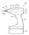
图1以示意图示出了根据一种实施方案的具有嵌入式工具的手持式工具机; FIG. 1 shows a schematic diagram of a hand-held power tool with an embedded tool according to an embodiment;
图2以透视图示出了具有图1的工具接纳部的输出轴,其具有根据一种实施方案的锁紧机构; FIG. 2 shows in a perspective view the output shaft with the tool receptacle of FIG. 1 with a locking mechanism according to one embodiment;
图3以透视分解图示出了在安装图2的锁紧机构时具有图1和2的工具接纳部的输出轴; Figure 3 shows the output shaft with the tool receiver of Figures 1 and 2 in a perspective exploded view when the locking mechanism of Figure 2 is installed;
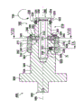
图4示出了沿输出轴的纵向的剖视图,该输出轴具有工具接纳部和图2和3中处于锁紧位置中的锁紧机构,以及根据第一实施方案的复位装置; Figure 4 shows a sectional view in the longitudinal direction of the output shaft with the tool receptacle and the locking mechanism in the locked position in Figures 2 and 3, and the reset device according to the first embodiment;
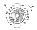
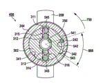
图5示出了沿图4的箭头V-V的方向观察沿图4的布置的横向的剖视图; Figure 5 shows a cross-sectional view along the transverse direction of the arrangement of Figure 4 viewed in the direction of the arrow V-V of Figure 4;
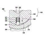
图6示出了沿图4的箭头VI-VI的方向观察沿图4的布置的一部分的横向的放大剖视图; Fig. 6 shows an enlarged cross-sectional view along the transverse direction of a part of the arrangement of Fig. 4 viewed in the direction of arrow VI-VI of Fig. 4;
图7示出了沿输出轴的纵向的剖视图,该输出轴具有工具接纳部和图2和3中处于解锁位置中的锁紧机构; FIG. 7 shows a sectional view in the longitudinal direction of the output shaft with the tool receptacle and the locking mechanism in the unlocked position in FIGS. 2 and 3 ;
图8示出了沿图7的箭头VIII-VIII的方向观察沿图7的布置的横向的剖视图; Fig. 8 shows a cross-sectional view along the direction of arrow VIII-VIII of Fig. 7 viewed along the arrangement of Fig. 7;
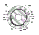
图9示出了沿图7的箭头IX-IX的方向观察沿图7的布置的一部分的横向的放大剖视图; Fig. 9 shows an enlarged cross-sectional view along the transverse direction of a part of the arrangement of Fig. 7 viewed in the direction of arrow IX-IX of Fig. 7;
图10示出了图7的布置的一部分X的放大剖视图,所述布置具有根据第二实施方案的复位装置; Figure 10 shows an enlarged cross-sectional view of a part X of the arrangement of Figure 7 with a reset device according to a second embodiment;
图11示出了沿图10的箭头XI-XI的方向观察在图7的锁紧机构解锁时沿图7中具有图10的复位装置的布置的横向的剖视图; Fig. 11 shows a cross-sectional view along the direction of arrow XI-XI of Fig. 10 along the arrangement of the reset device of Fig. 10 in Fig. 7 when the locking mechanism of Fig. 7 is unlocked;
图12示出了在图7的锁紧机构锁紧时图11的剖视图; Fig. 12 shows the sectional view of Fig. 11 when the locking mechanism of Fig. 7 is locked;
图13示出了图4的布置的一部分XIII的放大剖视图,该布置具有根据第三实施方案的复位装置; Figure 13 shows an enlarged cross-sectional view of part XIII of the arrangement of Figure 4 with a reset device according to a third embodiment;
图14以透视图示出了图13的复位装置的扭簧和支承盘,以及 Fig. 14 has shown the torsion spring and support plate of the resetting device of Fig. 13 in perspective view, and
图15示出了在图4的锁紧机构锁紧时沿图13的箭头XV-XV的方向观察沿图4中具有图13的复位装置的布置的横向的剖视图。 FIG. 15 shows a cross-sectional view of the arrangement in FIG. 4 with the reset device of FIG. 13 , viewed in the direction of arrow XV-XV in FIG. 13 when the locking mechanism of FIG. 4 is locked.
具体实施方案 specific implementation plan
图1示出了具有工具接纳部150的手持式工具机100,该手持式工具机具有带有手柄126的壳体110。根据一种实施方案,手持式工具机100可机械地且电地与蓄电池组130连接,用来实现与电网无关的供电。
FIG. 1 shows a
手持式工具机100例如设计为充电式冲击扳手(Akku-Drehschlagschrauber)。然而要指出,本发明不局限于充电式冲击扳手,反而还可以使用在不同的电动工具中,其中例如对螺丝刀、钻式螺栓拧紧机、冲击式钻机等来说,电动工具是与电源无关地利用蓄电池组驱动还是可电源无关地驱动,与此无关地使工具旋转。此外要指出,本发明不局限于马达驱动的手持式工具机,而是对工具来说普遍可用,对这些工具来说可使用图2至9中描述的工具接纳部150。
Hand-held
在壳体110中布置了由蓄电池组130供电的电驱动马达114、传动装置118和冲击机构122。例如,驱动马达114可通过手动开关128来操纵、即接通和切断,且可以是任意的马达形式,例如电子整流马达或直流电机。驱动马达114优选以下述方式进行电子控制或调节,使得不仅能实现可逆运行,而能在期望的转速方面实现预先规定。从现有技术中充分已知适合的驱动马达的工作原理和结构,因此为了使描述简洁在此不再进行描述。
An
驱动马达114通过配属的马达轴116与传动装置118相连接,该传动装置将马达轴116的旋转转换成设置在传动装置118和冲击机构122之间的驱动轴120的旋转。该转换优选这样进行,使得驱动轴120相对于马达轴116以增大的转矩、但缩小的转速进行旋转。驱动马达114说明性地设置在马达壳体115中,而传动装置118设置在传动装置壳体119中,其中传动装置壳体119和马达壳体115示例性地设置在壳体110中。
与驱动轴120连接的冲击机构122示例性地是旋转或转动冲击机构,该旋转或转动冲击机构产生了高强度的冲击式旋转脉冲并传递至输出轴124、例如输出主轴。在输出轴124上设置了工具接纳部150,工具接纳部优选设计用于接纳嵌入式工具并根据一种实施方案即可与具有外多边结合部142的嵌入式工具140连接也可与具有内多边结合部的嵌入式工具、例如套筒扳手连接。嵌入式工具140示例性地设计为具有外多边结合部142、例如八边形结合器的螺丝刀头或者说工具头(Schrauberbit), 其布置在工具接纳部150的适合的内接纳部(图2中的290)中。这种螺丝刀头以及合适的套筒扳手已经由现有技术充分已知,因此为了使描述简洁在此省略了详细的描述。
The
图2示出图1的输出轴124,其在图1中具有从动凸轮208的近端(近身体)端部区域202与手持式工具机100的冲击机构122连接。在输出轴124上设有工具接纳部150,在其远端(远离身体)端部区域204中说明性地形成轴向扩展部220。该轴向扩展部优选形成在工具接纳部150上并优选与工具接纳部一体形成。
FIG. 2 shows the
具有外接纳部210和内接纳部290的工具接纳部150说明性地形成在输出轴124上且优选与输出轴一体形成。为外接纳部210配设了优选可弹性变形的保持部件230且为内接纳部290配设了可操纵的锁紧机构240。
A
内接纳部290用于接纳图1的螺丝刀头140且示例性地按照多边内接纳部的类型形成在输出轴124内部,说明性地按照八边形内成型部250的类型。为内接纳部290配设了可通过优选设计成操纵套筒的操纵元件244来操纵的锁紧机构240,该锁紧机构用于锁紧图1的螺丝刀头140。
The
外接纳部210示例性地为多边外接纳部,优选四边外接纳部,沿径向看该四边外接纳部说明性地具有四个优选平坦的侧面261、262、263、264且根据一种实施方案设计用于接纳根据欧洲或北美工业标准制造的具有内多边结合部的嵌入式工具,例如套筒扳手。侧面261、262、263、264通过斜棱彼此连接,例如面261和262通过斜棱251彼此连接,而面262和263通过斜棱253彼此连接。斜棱本身具有朝向轴向扩展部220的斜面端部区域,例如棱251、253具有斜面端部区域252或254。轴向扩展部220具有封闭凸缘222,该封闭凸缘具有沿输出轴124的远端方向圆锥状倾斜的端部224。
The
为了把具有内多边结合部的适合的嵌入式工具固定在工具接纳部150上,设计了固定在轴向扩展部220上的保持部件230。说明性地,保持部件230具有设计为可弹性变形的、金属制C形环的保持元件234。
In order to fasten a suitable insert tool with an inner polygonal joint on the
图3示出了输出轴124,其具有工具接纳部150和轴向扩展部220、以及保持部件230和图2的锁紧机构240。图3用于示出保持部件230和锁紧机构240在该工具接纳部150或输出轴124上的示例性安装,该工具接纳部具有内接纳部290和外接纳部210。像从图3看出的那样,在外接纳部210的侧面263和264或264和261之间设有斜棱255或257。该斜棱具有斜面端部区域256或258。
FIG. 3 shows
根据一种实施方案,由从动凸轮208出发沿远端端部区域204的方向,输出轴124包括具有第一直径D1的第一优选圆柱状区段304。轴124在第一肩部303处渐缩且过渡至具有第二直径D2的第二圆柱状区段302,D2<D1。输出轴124在第二肩部399处再次渐缩且过渡至外接纳部210中,外接纳部本身在第三肩部398处过渡至轴向扩展部220。在第一肩部303的区域中,在第二圆柱状区段302上说明性地形成第一径向开口326。在第二肩部399的区域中,在区段302上形成至少一个第二径向开口315,为该第二径向开口示例性地配设了对角线对置的第三开口316。在第二肩部399和外接纳部210之间的区域中形成了至少一个槽状凹部286。优选设置四个槽状凹部,其中图3中仅可看到凹部286、287、288,它们分别形成在第二肩部399和配属的斜棱253、255或257之间。在轴向扩展部220上在第三肩部398和封闭凸缘222之间形成了形式为环状槽330的外部槽状凹部。
According to one embodiment, starting from the driven
要指出,对置的斜棱之间的距离,例如棱253和257之间的距离优选大致对应于输出轴124的第二区段302的直径D2,从而在这些斜棱253、257和第二肩部399之间形成上述槽状凹部286或288。四边外接纳部210的对置的侧面之间的距离,也就是说侧面261和263之间的距离或者侧面262和264之间的距离示例性地小于直径D2且优选如此设计,使得在侧面261、262、263、264和肩部399之间不形成凹部。然而同样也可以在侧面261、262、263、264和肩部399之间形成槽状凹部,此外该槽状凹部可以与槽状凹部286、287、288一起形成例如环状槽。
It should be pointed out that the distance between opposite beveled edges, for example the distance between
根据一种实施方案,锁紧机构240包括:操纵套筒244;根据螺栓形式设计的锁定部件242;示例性设计为C形环的锁止元件246;具有压力弹簧327和球体328的弹簧元件325,以及四个球体311、312、313、314。说明性地,操纵套筒244具有内周341,根据一种实施方案在该内周上设有两个解锁凹部345(和图5、7和8中的545)、凹部342和槽(图4、6、7和9中的428),在下文中在图4至9中描述它们的功能性。压力弹簧327和球体328可插到输出轴124的开口326中,球体311、312可插到开口315中且球体313、314可插到开口316中。压力弹簧327连同球体328和球体311、312、313、314由朝向从动凸轮208可推到输出轴124上的操纵套筒244保持在开口326、315或316中,像下文中图4描述的那样。
According to one specific embodiment, the
在锁紧机构240示例性地安装在工具接纳部150或输出轴124上时,在把压力弹簧327和球体328以及球体311、312、313、314插入开口326、315或316中之后,像下文中在图5的描述中那样首先锁定螺栓242,接着操纵套筒244最后具有径向扩展部247、248、249的锁止C形环246如此朝向从动凸轮208被推到输出轴124上,使得锁止C形环246接合到槽状凹部286、287、288中。因此,径向扩展部247、248、248锁紧了操作套筒244并把锁紧机构240固定在输出轴124上。
When the
然而要指出,在本发明的框架描述的、根据本发明的具有图3中的工具接纳部150的锁紧机构240的应用仅具有示例性的特征且不应理解为对本发明的限制。而锁紧机构240可应用在不同的工具接纳部中,例如各种在DE10 2010 002 352A1和DE 10 2010 002 353A1中示出的工具接纳部中。
However, it should be pointed out that the use of the
根据一种实施方案,保持部件230具有图2中的金属制C形环234,和优选设计为O形环的由弹性橡胶材料制成的弹簧元件334。它们用于,在安装后向C形环234径向加载预定的弹力。为了把保持部件230安装在轴向扩展部220上,首先将弹性O形环334经由封闭凸缘222推到或压到环形槽330中。随后,金属制C形环234径向地布置在O形环334上,例如被推动经过封闭凸缘222。
According to one embodiment, the retaining
图4示出了在上述图3中描述的锁紧机构240和图3的保持部件230的安装之后,具有输出轴124、工具接纳部150和图2的轴向扩展部220的布置400。在此,示出了处于所属的锁紧位置中的锁紧机构240,其中球体311、312、313、314从操纵套筒244的内周341径向向内被压入开口315或316中。为了使锁紧机构240从锁紧位置移动至解锁位置中,操纵套筒244必须沿箭头450的方向旋转,像下面图5和6中描述的那样。
FIG. 4 shows an
像从图4看到的那样,根据一种实施方案,操纵套筒244布置为与工具接纳部150的纵轴线499共轴且在第一肩部303和锁止C形环246之间轴向不可移动,然而可围绕纵轴线499沿着或逆着箭头450的方向旋转。在套筒244的内周341上形成的槽428中至少部分地布置了弹簧元件325的球体328。弹簧元件325、开口326和槽428形成了根据第一实施方案的复位装置。
As can be seen from FIG. 4 , according to one embodiment, the
图5示出了图4中的布置400,其具有从操纵套筒244的内周341径向向内朝向八边形内成型部250被挤压的、布置在开口315、316中的球体311、312或313、314。锁定螺栓242一方面部分地布置在设置在图4的输出轴124的第二区段302上的凹部542中,且另一方面部分地布置在设置在操纵套筒244上的凹部342中。在凹部上形成两个肩状止动部件541、543,该止动部件用于阻止操纵套筒244旋转越过预定的锁紧位置或预定的解锁位置。在图5中示出的锁紧位置中止动肩部543抵靠在锁定螺栓242上。
FIG. 5 shows the
当操纵套筒244沿箭头450的方向旋转时,凹部342在锁定螺栓242移动上,直至止动肩部541抵靠在螺栓242上并进而达到解锁位置。在此,形成在套筒244的内周341上的解锁凹部345以及形成在其上的另一解锁凹部545定位在球体314或311上,像下文图8中描述的那样。
When the
图6示出了图4的布置400的弹簧元件325,其中压力弹簧327沿箭头666的方向将球体328挤压到形成在操纵套筒244上的槽428中根据实施方案最大径向向外设置的位置中,槽相应于图4的锁紧机构240的锁紧位置。在此,球体328抵靠在形成在槽428上、说明性地为肩状的止挡部628上。当操纵套筒244沿箭头450的方向旋转时,槽428在球体328上移动,直至球体328克服压力弹簧327的力被压入开口326中根据实施方案最大径向向内设置的位置中,像下文图9中描述的那样。
FIG. 6 shows the
图7示出了当操纵套筒244沿图4的箭头450的方向旋转至所属的解锁位置中之后图4的布置400,在该解锁位置中布置在开口315或316中的球体311、312、313、314如此可径向向外移动,使得球体311、314至少部分地能接合到设置在操纵套筒244的内周341上的解锁凹部545或345中。为了使锁紧机构240从解锁位置移动回至图4中示出的锁紧位置中,操纵套筒244必须沿箭头750的方向旋转,像下文图8和9中描述的那样。此外,图7示出了克服压力弹簧327的力压入开口326中的球体328的、根据实施方案最大径向向内设置的位置。
FIG. 7 shows the
图8示出图7的布置400,其具有布置在球体311、314的区域内的解锁凹部545或345以及抵靠在螺栓242上的止动肩部541。在此,为了插入或取出具有外多边结合部的适合的嵌入式工具,例如具有图1的外多边结合部142的嵌入式工具140,球体311、312、313、314可沿所属的解锁凹部545或345的方向径向向外移动。
FIG. 8 shows the
像从图8看到的那样,操纵套筒244从图4至6示出的锁紧位置出发旋转了转动角888进入解锁位置中。该转动角888由形成在操纵套筒244的内周341上的凹部342的沿周向的延展预定并优选小于180°,优选小于90°,且尤其优选小于45°。在示出的实施方案中,转动角888说明性地为约40°。
As can be seen from FIG. 8 , the
图9示出了克服压力弹簧327的力沿箭头999的方向压入开口326中的球体328的、根据实施方案最大径向向内设置的位置。根据一种实施方案,图1的手持式工具机100的使用者必须把操纵套筒244锁紧或固定在该解锁位置中,以便阻止套筒244自动旋转至图4示出的锁紧位置中。当使用者释放操纵套筒244时,压力弹簧327如此沿反向于箭头999的方向,也就是说沿图6的箭头666的方向对球体328施压,使得槽428在球体328上移动,直至球体328抵靠在肩状止挡部628上,像上述图6描述的那样。因此,操纵套筒244自动地从解锁位置移动至锁紧位置中。
FIG. 9 shows the position of the
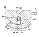
图10示出了图7的布置400的放大部分1000,其具有根据第二实施方案设置在该布置上的复位装置1025,可以使用该复位装置来替代布置在图7的开口326中且与槽428共同作用的图7的弹簧元件325。复位装置1025具有说明性地设计为压力弹簧的弹簧元件1050,该弹簧元件示例性地布置在设置在输出轴124的第二区段302中的、第一槽状凹部1010中以及设置在操纵套筒244中的、第二槽状凹部1044中。在可选的实施方案变型中,弹簧元件1050设计为牵拉弹簧。
FIG. 10 shows an enlarged part 1000 of the
图11示出了设计有图10中的复位装置1025的、图7的布置400,其中操纵套筒244说明性地旋转至解锁位置中。在该解锁位置中,必须克服由压力弹簧1050施加的压力来保持操纵套筒244,像下文描述的那样。
FIG. 11 shows the
像上文图10中描述的那样,压力弹簧1050布置在设置在输出轴124上的第一槽状凹部1010中以及设置在操纵套筒244中的第二槽状凹部1044中。第一槽状凹部1010在其端部上沿纵向示例性地具有固定肩部1111和对置的肩部1113。第二槽状凹部1044在其端部上沿纵向示例性地具有固定肩部1143和对置的肩部1141。在固定肩部1111和1143上分别说明性地固定了压力弹簧1050的轴向端部,以便进而实现复位装置1025的稳定性的改进。
As described above in FIG. 10 , the
然而要指出,压力弹簧1050也可以不固定地布置凹部1010、1044中,只要确保:在图1的手持式工具机100的运行中,压力弹簧不会例如仅滑入或压入凹部1010、1044之一中。例如这可以通过下述方式避免,即压力弹簧1050的直径选择为关于凹部1010或1044的高度相对较大。
However, it should be pointed out that the
根据一种实施方案,压力弹簧1050在固定肩部1111、1143之间的解锁位置中被压缩。当释放操纵套筒244时,压力弹簧1050伸展并进而引起操纵套筒244相对于驱动轴124沿箭头1150的方向旋转,其中操纵套筒244移动到图12示出的锁紧位置中。
According to one embodiment, the
图12示出了图11中的剖视图,其中操纵套筒244说明性地由于压力弹簧1050的伸展已经自动沿图11的箭头1150的方向旋转到锁紧位置中。操纵套筒244由伸展的压力弹簧1050施加的压力被保持在该锁紧位置中。由于操纵套筒244克服压力弹簧1050的压力沿箭头1250的方向的旋转,则操纵套筒244可以重新移动到图11中示出的解锁位置中。在此,操纵套筒244仅能旋转预定的转动角,例如图8的转动角888,像上文图8中描述的那样。
FIG. 12 shows the sectional view in FIG. 11 , wherein the
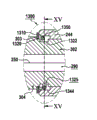
图13示出图4的布置400的放大部分1300,其具有设置在其上的根据第三实施方案的复位装置1325,其中可以使用该复位装置1325来替代布置在图4的开口326中且与槽428共同作用的图4的弹簧元件325。复位装置1325具有说明性地设计为扭簧的弹簧元件1350,该弹簧元件示例性地布置在设置在输出轴124的第二区段302中的、第一槽状凹部1322中以及设置在操纵套筒244中的、第二槽状凹部1344中。
FIG. 13 shows an
根据一种实施方案,在图1的手持式工具机100的运行中,或在操纵套筒244解锁时,说明性地通过支承盘1310阻止扭簧1350沿输出轴124的第一区段304的方向的滑动。该支承盘支承在阶梯1320的区域中输出轴124的第一区段304和第二区段302之间的肩部303上。阶梯1320形成从肩部303至槽状凹部1322的过渡部。
According to one specific embodiment, during operation of the hand-held
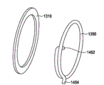
图14示出了图13的支承盘1310和扭簧1350的示例性实施方案。支承盘1310说明性地设计为环状。扭簧1350在其第一弹簧端部1452和其第二弹簧端部1454之间说明性地围成约450°的角度。然而要指出,角度450°的图示仅具有示例性特征且并不限制本发明。然而,也可以使用多个不同的扭簧,该扭簧包括多个不同角度,只要保证下文图15中描述的功能性。
FIG. 14 shows an exemplary embodiment of the
图15示出了利用图13的复位装置1325实施的图4的布置400,其中操纵套筒244说明性地旋转至锁紧位置中。操纵套筒244可以从该锁紧位置克服由扭簧1350施加的复位力沿箭头1550的方向旋转至解锁位置中。
FIG. 15 shows the
像从图15看到的那样,在操纵套筒244的锁紧位置中,扭簧1350基本上支承在设置在输出轴124的第二区段302中的、第一槽状凹部1322中,其中第一弹簧端部1452说明性地抵靠在第一保持肩部1522上,该第一保持肩部形成在设置在凹部1322中的凹槽1517中。此外,扭簧1350部分地布置在设置在操纵套筒244中的、第二槽状凹部1344中,其中第二弹簧端部1454说明性地抵靠在第二保持肩部1543上,该第二保持肩部形成在设置于凹部1344中的凸起部1546上。
As can be seen from FIG. 15 , in the locked position of the
根据一种实施方案,当操纵套筒244从锁紧位置沿箭头1550的方向旋转时,第二弹簧端部1454从第二保持肩部1543沿箭头1550的方向移动。由此,扭簧1350径向地扩展到槽状凹部1344中并进而承受负荷或被加应力,直至操纵套筒244到达解锁位置。在此,操纵套筒244的旋转仅能转过预定的转动角,例如图8的转动角888,像上文图8中描述的那样。因此当释放操纵套筒244时,操纵套筒由于被加应力的扭簧1350的复位力可以沿与箭头1550相反的方向移动回至图15示出的锁紧位置中。
According to one embodiment, when the
Claims (12)
Applications Claiming Priority (5)
| Application Number | Priority Date | Filing Date | Title |
|---|---|---|---|
| DE102010029829 | 2010-06-09 | ||
| DE102010029829.8 | 2010-06-09 | ||
| DE102010030642A DE102010030642A1 (en) | 2010-06-09 | 2010-06-29 | Hand tool with a tool holder |
| DE102010030642.8 | 2010-06-29 | ||
| PCT/EP2011/058057 WO2011154230A1 (en) | 2010-06-09 | 2011-05-18 | Portable machine tool comprising a tool fitting |
Publications (2)
| Publication Number | Publication Date |
|---|---|
| CN102917841A true CN102917841A (en) | 2013-02-06 |
| CN102917841B CN102917841B (en) | 2016-04-20 |
Family
ID=45020118
Family Applications (1)
| Application Number | Title | Priority Date | Filing Date |
|---|---|---|---|
| CN201180028186.6A Expired - Fee Related CN102917841B (en) | 2010-06-09 | 2011-05-18 | There is the hand held power machine of tool receiver head |
Country Status (6)
| Country | Link |
|---|---|
| US (1) | US9718173B2 (en) |
| EP (1) | EP2580022B1 (en) |
| KR (1) | KR101877716B1 (en) |
| CN (1) | CN102917841B (en) |
| DE (1) | DE102010030642A1 (en) |
| WO (1) | WO2011154230A1 (en) |
Cited By (2)
| Publication number | Priority date | Publication date | Assignee | Title |
|---|---|---|---|---|
| CN104416545A (en) * | 2013-08-23 | 2015-03-18 | 苏州宝时得电动工具有限公司 | Electric tool end socket connection accessory and electric tool |
| CN111819034A (en) * | 2018-03-08 | 2020-10-23 | 罗伯特·博世有限公司 | hand-held power tool |
Families Citing this family (14)
| Publication number | Priority date | Publication date | Assignee | Title |
|---|---|---|---|---|
| US9463557B2 (en) * | 2014-01-31 | 2016-10-11 | Ingersoll-Rand Company | Power socket for an impact tool |
| US10427277B2 (en) | 2011-04-05 | 2019-10-01 | Ingersoll-Rand Company | Impact wrench having dynamically tuned drive components and method thereof |
| US9469017B2 (en) | 2014-01-31 | 2016-10-18 | Ingersoll-Rand Company | One-piece power socket for an impact tool |
| DE202011107082U1 (en) * | 2011-10-24 | 2012-04-03 | Robert Bosch Gmbh | Hand tool |
| US9630307B2 (en) | 2012-08-22 | 2017-04-25 | Milwaukee Electric Tool Corporation | Rotary hammer |
| US9815179B2 (en) | 2012-09-26 | 2017-11-14 | Apex Brands, Inc. | Reversible ratcheting tool with dual pawls |
| US11007631B2 (en) | 2014-01-15 | 2021-05-18 | Milwaukee Electric Tool Corporation | Bit retention assembly for rotary hammer |
| JP6063014B1 (en) * | 2015-08-31 | 2017-01-18 | ファナック株式会社 | Chuck device and robot for exchanging welding tips and nozzles |
| DE102017121171A1 (en) * | 2017-09-13 | 2019-03-14 | Ferrobotics Compliant Robot Technology Gmbh | METHOD AND SYSTEM FOR AUTOMATIC SWITCHING OF WAVES |
| JP6624578B1 (en) * | 2018-12-11 | 2019-12-25 | 近江精機株式会社 | Trauma prevention cover |
| US11980948B2 (en) * | 2019-12-26 | 2024-05-14 | Koki Holdings Co., Ltd. | Rotary tool |
| JP7535905B2 (en) * | 2020-10-13 | 2024-08-19 | 株式会社マキタ | Impact wrench |
| DE102022209287A1 (en) * | 2022-09-07 | 2024-03-07 | Robert Bosch Gesellschaft mit beschränkter Haftung | Hand tool with a tool holder and a locking unit |
| SE547444C2 (en) * | 2023-05-31 | 2025-09-30 | Husqvarna Ab | Tool driver, locking member and arrangement, tool holder and concrete surface processing equipments |
Citations (3)
| Publication number | Priority date | Publication date | Assignee | Title |
|---|---|---|---|---|
| US2518139A (en) * | 1946-03-06 | 1950-08-08 | Standard Pressed Steel Co | Magazine tool |
| US5481949A (en) * | 1994-08-15 | 1996-01-09 | Yen; En-Ji | Locking member for use in hand tools |
| CN201283554Y (en) * | 2008-09-15 | 2009-08-05 | 车王电子股份有限公司 | Screw locking nail depth adjusting device |
Family Cites Families (22)
| Publication number | Priority date | Publication date | Assignee | Title |
|---|---|---|---|---|
| US864992A (en) * | 1904-12-29 | 1907-09-03 | Charles C Roberts | Drill socket or chuck. |
| US973345A (en) * | 1910-01-06 | 1910-10-18 | Peter J Quinn | Drill-chuck. |
| US1162197A (en) * | 1914-12-22 | 1915-11-30 | Wahlstrom Tool Company | Chuck. |
| US1351347A (en) * | 1918-12-06 | 1920-08-31 | Russell Charles Lyon | Drill-chuck |
| DE1969989U (en) * | 1967-07-24 | 1967-10-05 | Hilti Ag | TOOL HOLDER FOR DRILLS. |
| US4002348A (en) * | 1975-05-07 | 1977-01-11 | Tapmatic Corporation | Safety release device useful in tapping attachments |
| US4708548A (en) * | 1982-12-15 | 1987-11-24 | Peter Taylor | Releasable coupling |
| US4563116A (en) * | 1984-05-16 | 1986-01-07 | Edens Rudolph R | Tool holder with coolant inducer |
| DE3421811C2 (en) * | 1984-06-12 | 1995-11-16 | Hilti Ag | Tool holder for drilling and chiseling tools |
| US5577743A (en) * | 1995-05-10 | 1996-11-26 | Power Tool Holders, Inc. | Quick release chuck device |
| US6679143B2 (en) * | 2001-04-13 | 2004-01-20 | Omnitek Partners, Llc | Manually operated impact tool |
| US6932358B1 (en) * | 2002-10-31 | 2005-08-23 | Lomar Machine & Tool Co. | Quick change endform tool cartridge |
| US20040104545A1 (en) * | 2002-12-02 | 2004-06-03 | Tsai-Ching Chen | Connection of tool with tool bit |
| DE20317932U1 (en) * | 2003-11-20 | 2004-02-05 | Chen, Yu-Tang | Electrical hand tool with splined rotary drive system, includes recess accepting drive section, in which projecting splines have convex side surfaces |
| TWM249763U (en) * | 2003-12-18 | 2004-11-11 | Pumtec Entpr Co Ltd | Dual purpose transmission shaft for manual/pneumatic ratchet wrench |
| JP4832145B2 (en) * | 2005-05-31 | 2011-12-07 | ユキワ精工株式会社 | Rotating tool |
| US7028589B1 (en) | 2005-06-29 | 2006-04-18 | Ming-Ta Cheng | Resilient positioning assembly for an axle in a power tool |
| DE102006061757A1 (en) * | 2006-12-28 | 2008-07-03 | Protool Gmbh | Stripping part on a hand tool |
| US8020876B2 (en) * | 2007-04-04 | 2011-09-20 | Hung Wei Lin | Tool having clamping chuck |
| DE602007008424D1 (en) | 2007-09-24 | 2010-09-23 | Bosch Gmbh Robert | Rotating tool with numerous interfaces for tool attachment |
| DE102010002352B4 (en) | 2010-02-25 | 2021-03-18 | Robert Bosch Gmbh | Hand machine tool |
| DE102010002353A1 (en) | 2010-02-25 | 2011-08-25 | Robert Bosch GmbH, 70469 | Hand tool |
-
2010
- 2010-06-29 DE DE102010030642A patent/DE102010030642A1/en not_active Withdrawn
-
2011
- 2011-05-18 US US13/703,165 patent/US9718173B2/en not_active Expired - Fee Related
- 2011-05-18 WO PCT/EP2011/058057 patent/WO2011154230A1/en not_active Ceased
- 2011-05-18 CN CN201180028186.6A patent/CN102917841B/en not_active Expired - Fee Related
- 2011-05-18 EP EP11720112.9A patent/EP2580022B1/en not_active Not-in-force
- 2011-05-18 KR KR1020127031957A patent/KR101877716B1/en not_active Expired - Fee Related
Patent Citations (3)
| Publication number | Priority date | Publication date | Assignee | Title |
|---|---|---|---|---|
| US2518139A (en) * | 1946-03-06 | 1950-08-08 | Standard Pressed Steel Co | Magazine tool |
| US5481949A (en) * | 1994-08-15 | 1996-01-09 | Yen; En-Ji | Locking member for use in hand tools |
| CN201283554Y (en) * | 2008-09-15 | 2009-08-05 | 车王电子股份有限公司 | Screw locking nail depth adjusting device |
Cited By (3)
| Publication number | Priority date | Publication date | Assignee | Title |
|---|---|---|---|---|
| CN104416545A (en) * | 2013-08-23 | 2015-03-18 | 苏州宝时得电动工具有限公司 | Electric tool end socket connection accessory and electric tool |
| CN104416545B (en) * | 2013-08-23 | 2016-08-10 | 苏州宝时得电动工具有限公司 | Electric tool termination connects adnexa and electric tool |
| CN111819034A (en) * | 2018-03-08 | 2020-10-23 | 罗伯特·博世有限公司 | hand-held power tool |
Also Published As
| Publication number | Publication date |
|---|---|
| DE102010030642A1 (en) | 2011-12-15 |
| US9718173B2 (en) | 2017-08-01 |
| EP2580022A1 (en) | 2013-04-17 |
| US20130154202A1 (en) | 2013-06-20 |
| CN102917841B (en) | 2016-04-20 |
| EP2580022B1 (en) | 2015-07-08 |
| WO2011154230A1 (en) | 2011-12-15 |
| KR20130109953A (en) | 2013-10-08 |
| KR101877716B1 (en) | 2018-07-13 |
Similar Documents
| Publication | Publication Date | Title |
|---|---|---|
| CN102917841B (en) | There is the hand held power machine of tool receiver head | |
| CN103958129B (en) | Hand held power machine | |
| CN103042508B (en) | Tool attachment | |
| US10478959B2 (en) | Hand-held power tool | |
| US20110233878A1 (en) | Hand-held power tool | |
| US8136607B2 (en) | Device having a torque-limiting unit | |
| CN102762327B (en) | Hand held power machine | |
| US10661421B2 (en) | Tool attachment for a handheld power tool | |
| CN105102190A (en) | Tool attachment for a hand-held power tool | |
| US10272557B2 (en) | Power tool | |
| US20190217400A1 (en) | Quick Release Adapter | |
| CN102958633A (en) | Hand-held machine tools with impact mechanism | |
| US6988734B2 (en) | Rotating machine, approximately in the form of a hand drill, a percussion drill, a drill hammer or a battery screwdriver | |
| CN104057414A (en) | Hand-held Machine Tool Provided With Machine Tool Accommodating Device Comprising Polygonal Inner Accommodating Device And Polygonal Outer Accommodating Device | |
| WO2003011533A3 (en) | Battery powered screwdriver and screw starting device | |
| KR102654990B1 (en) | portable power tools | |
| CN204094753U (en) | For the attachment of hand tool, hand tool and tool system | |
| CN103381590A (en) | Hand-held power tool | |
| CN101204739B (en) | Electric hand-held power tool with tool locking system | |
| CN104440802A (en) | Handheld tool machine | |
| CN115338832A (en) | Hand-held power tool | |
| CN108145663B (en) | Adapter for clamping round shank insert tool | |
| CN110065023A (en) | Holding meanss for hand held power machine | |
| US20260091471A1 (en) | Depth setting bit drivers, systems and related methods | |
| CN209936841U (en) | Chuck assembly and hand-held machine tool using same |
Legal Events
| Date | Code | Title | Description |
|---|---|---|---|
| C06 | Publication | ||
| PB01 | Publication | ||
| C10 | Entry into substantive examination | ||
| SE01 | Entry into force of request for substantive examination | ||
| C14 | Grant of patent or utility model | ||
| GR01 | Patent grant | ||
| CF01 | Termination of patent right due to non-payment of annual fee |
Granted publication date: 20160420 |
|
| CF01 | Termination of patent right due to non-payment of annual fee |