CN102906339A - Device for assisting in installing a pile in the seabed, offshore foundation structure and method of establishing an offshore foundation - Google Patents
Device for assisting in installing a pile in the seabed, offshore foundation structure and method of establishing an offshore foundation Download PDFInfo
- Publication number
- CN102906339A CN102906339A CN2010800670963A CN201080067096A CN102906339A CN 102906339 A CN102906339 A CN 102906339A CN 2010800670963 A CN2010800670963 A CN 2010800670963A CN 201080067096 A CN201080067096 A CN 201080067096A CN 102906339 A CN102906339 A CN 102906339A
- Authority
- CN
- China
- Prior art keywords
- stake
- sea bed
- marine
- foundation structure
- equipment
- Prior art date
- Legal status (The legal status is an assumption and is not a legal conclusion. Google has not performed a legal analysis and makes no representation as to the accuracy of the status listed.)
- Granted
Links
Images

Classifications
-
- E—FIXED CONSTRUCTIONS
- E02—HYDRAULIC ENGINEERING; FOUNDATIONS; SOIL SHIFTING
- E02D—FOUNDATIONS; EXCAVATIONS; EMBANKMENTS; UNDERGROUND OR UNDERWATER STRUCTURES
- E02D27/00—Foundations as substructures
- E02D27/32—Foundations for special purposes
- E02D27/52—Submerged foundations, i.e. submerged in open water
-
- E—FIXED CONSTRUCTIONS
- E02—HYDRAULIC ENGINEERING; FOUNDATIONS; SOIL SHIFTING
- E02D—FOUNDATIONS; EXCAVATIONS; EMBANKMENTS; UNDERGROUND OR UNDERWATER STRUCTURES
- E02D27/00—Foundations as substructures
- E02D27/32—Foundations for special purposes
- E02D27/42—Foundations for poles, masts or chimneys
- E02D27/425—Foundations for poles, masts or chimneys specially adapted for wind motors masts
-
- F—MECHANICAL ENGINEERING; LIGHTING; HEATING; WEAPONS; BLASTING
- F03—MACHINES OR ENGINES FOR LIQUIDS; WIND, SPRING, OR WEIGHT MOTORS; PRODUCING MECHANICAL POWER OR A REACTIVE PROPULSIVE THRUST, NOT OTHERWISE PROVIDED FOR
- F03D—WIND MOTORS
- F03D13/00—Assembly, mounting or commissioning of wind motors; Arrangements specially adapted for transporting wind motor components
- F03D13/20—Arrangements for mounting or supporting wind motors; Masts or towers for wind motors
- F03D13/22—Foundations specially adapted for wind motors
-
- F—MECHANICAL ENGINEERING; LIGHTING; HEATING; WEAPONS; BLASTING
- F05—INDEXING SCHEMES RELATING TO ENGINES OR PUMPS IN VARIOUS SUBCLASSES OF CLASSES F01-F04
- F05B—INDEXING SCHEME RELATING TO WIND, SPRING, WEIGHT, INERTIA OR LIKE MOTORS, TO MACHINES OR ENGINES FOR LIQUIDS COVERED BY SUBCLASSES F03B, F03D AND F03G
- F05B2240/00—Components
- F05B2240/90—Mounting on supporting structures or systems
- F05B2240/95—Mounting on supporting structures or systems offshore
-
- Y—GENERAL TAGGING OF NEW TECHNOLOGICAL DEVELOPMENTS; GENERAL TAGGING OF CROSS-SECTIONAL TECHNOLOGIES SPANNING OVER SEVERAL SECTIONS OF THE IPC; TECHNICAL SUBJECTS COVERED BY FORMER USPC CROSS-REFERENCE ART COLLECTIONS [XRACs] AND DIGESTS
- Y02—TECHNOLOGIES OR APPLICATIONS FOR MITIGATION OR ADAPTATION AGAINST CLIMATE CHANGE
- Y02E—REDUCTION OF GREENHOUSE GAS [GHG] EMISSIONS, RELATED TO ENERGY GENERATION, TRANSMISSION OR DISTRIBUTION
- Y02E10/00—Energy generation through renewable energy sources
- Y02E10/70—Wind energy
- Y02E10/72—Wind turbines with rotation axis in wind direction
-
- Y—GENERAL TAGGING OF NEW TECHNOLOGICAL DEVELOPMENTS; GENERAL TAGGING OF CROSS-SECTIONAL TECHNOLOGIES SPANNING OVER SEVERAL SECTIONS OF THE IPC; TECHNICAL SUBJECTS COVERED BY FORMER USPC CROSS-REFERENCE ART COLLECTIONS [XRACs] AND DIGESTS
- Y02—TECHNOLOGIES OR APPLICATIONS FOR MITIGATION OR ADAPTATION AGAINST CLIMATE CHANGE
- Y02E—REDUCTION OF GREENHOUSE GAS [GHG] EMISSIONS, RELATED TO ENERGY GENERATION, TRANSMISSION OR DISTRIBUTION
- Y02E10/00—Energy generation through renewable energy sources
- Y02E10/70—Wind energy
- Y02E10/727—Offshore wind turbines
Abstract
A method of establishing an offshore foundation (1) on the seabed, in particular of establishing an offshore foundation for a wind turbine installation on the seabed, is provided. In this method, an offshore foundation structure (1) comprising at least one leg (7) is set on the seabed (3) and anchored in the seabed (3) by means of a pile (10) extending from the leg into the seabed (3). The anchoring is done by flushing the pile (10) into the seabed (3).
Description
Technical field
The present invention relates to auxiliary stake is installed in equipment in the sea bed.In addition, the method that the present invention relates to marine foundation structure and set up marine basis.
Background technology
It is known setting up the basis that single pile, cannula configuration or tripod structure install especially for offshore wind turbine as the basis at sea bed.The single pile structure of for example describing among WO 2009/026933 Al.For example US 5,988,949 and EP 2 067 914 A2 cannula configuration has been described, and for example DE 10 2,004 042 066 Al have described the tripod structure.
The typical method of setting up the basis basis of cannula configuration or tripod structure (particularly based on) is to prepare sea bed before setting up the basis, comprises that the differing heights of smooth sea bed is so that the acquisition horizontal tectonics.In addition, the method is included in and sets up the very exactly stake of location in the sea bed, for example passes through the stake locating template structure of prefabricated on sea bed or pre-determined bit.Described stake is as the anchor on marine basis.
By using for example hydraulic pressure mole foundation stake, this mole is knocked in stake in the sea bed downwards.When setting up stake, sleeve pipe or tripod structure are placed be in the milk to set up firmly on the part of stake (perhaps, being a plurality of stakes in tripod structure or cannula configuration situation) and to the space between supporting leg and the stake to connect.
Summary of the invention
With regard to above-mentioned prior art level, an object of the present invention is to provide a kind of and favourable auxiliary stake is installed in equipment in the sea bed.Further purpose is that a kind of favourable marine foundation structure and the method for setting up marine basis will be provided.
First purpose realizes that by a kind of auxiliary equipment that stake is installed in the sea bed wherein this stake will be used to the marine basis of grappling.Further purpose realizes by marine foundation structure claimed in claim 7 and by the described method of setting up marine basis of claim 11.Dependent claims has comprised the present invention further to be improved.
The equipment that the auxiliary stake that will be used for the marine basis of grappling of the present invention be installed in sea bed comprise nozzle and for generation of the device of the water jet that sprays from described nozzle.Described water jet and produces low resistance to stake to be positioned thus so that the sea bed material eddies.Described integration of equipments is to the described stake that is used for the marine basis of grappling.In this case, described stake can comprise the tip, and the nozzle of described equipment is arranged in described tip.Perhaps, described equipment can be so that the autonomous device of sea bed material production whirlpool.Then thereby the material that penetrates by punching pick (flush) is tightly followed in stake after described equipment.
Auxiliary stake is installed in equipment in the sea bed can comprises by what for example one or more flexible pipes were connected to nozzle and rush the pick control device.Especially, if described integration of equipments is anchored on marine basis in the stake of sea bed to being used for, then punching pick control device can be integrated in the stake.Perhaps, punching pick control device can be outside stake.
Equipment of the present invention helps that (drifting) beaten in stake and enters in the sea bed.Especially, the equipment of the application of the invention, the installation of stake does not need specialized ships or heavy apparatus.In addition, can operate concurrently two or more equipment of the present invention, thereby can simultaneously two or more stakes be squeezed in the sea bed, this has saved the time, thereby also saves cost.
In addition, equipment of the present invention provides the chance of the whole structure of once mounting (such as tripod or cannula configuration), has minimized thus the time that expensive specialized ships is installed that occupies.
The marine foundation structure (especially for the marine basis of wind turbine) that will be installed on the sea bed of the present invention comprises at least one foot that described marine foundation structure is anchored on described sea bed and stake.Described marine foundation structure, stake that for example should sea foundation structure comprises of the present inventionly auxiliary stake being installed in equipment in the sea bed.Utilize so foundation structure of design, auxiliaryly stake is installed in the advantage that the equipment in the sea bed mentions all can be implemented in the described marine foundation structure with reference to described.
At sea in first specific embodiment of foundation structure, this structure comprises at least one hollow leg with inner hollow space.Stake is positioned at this hollow space.This foundation structure can be positioned such that foot on described sea bed, then by stake being squeezed into marine being anchored.Therefore marine foundation structure of the present invention has overcome the needs of stake pre-installation in being provided with the sea bed of described structure.Pre-installation the stake need to be positioned very accurately, thereby typical three or more supporting legs of tripod or sleeve structure can be placed in from the sea bed projection the end on.Therefore, these stakes of pre-installation are very complicated.Utilization is according to the of the present invention marine foundation structure of described embodiment, can be with the grappling process simplification for not needing pre-installation accurately to be used for the stake of the described structure of grappling.
In another embodiment, marine foundation structure comprises at least one supporting leg with foot and the stake of extending from described foot.In other words, stake is fixed to foot, thereby from described foot to the sea bed projection.Then by the described auxiliary equipment that stake is installed in the sea bed stake is squeezed in the sea bed with the foundation structure that connects with stake.This means that can be placed on whole marine foundation structure on the sea bed and anchor in the sea bed by single processing step, this have saved the time, thereby also provides cost savings.Because the sea bed material resistance by punching pick is low, therefore in addition the promotion of weight that can be by this structure the basis is placed on the sea bed.
In the method for setting up marine basis (particularly setting up the marine basis that is used for wind turbine at sea bed) at sea bed of the present invention, the marine foundation structure that comprises at least one supporting leg is arranged on the sea bed, and is anchored in the sea bed by the stake that extends to from supporting leg the sea bed.The method according to this invention is by the stake punching is dug in the sea bed at least one supporting leg to be anchored in the sea bed.For stake punching is dug in the sea bed, used of the present inventionly auxiliary stake to be installed in equipment in the sea bed.Described equipment can be integrated in the stake, perhaps can be an external equipment, and this external equipment eddies the material of sea bed, thereby so that described stake can be driven in the sea bed by tightly following described equipment after, to penetrate in the material of being dug by punching.
In first embodiment of the inventive method, stake is gone out after upper from the inner hollow space of marine foundation structure supporting leg marine foundation structure being arranged on seabed (ground), rush and be dug in the sea bed.
Marine foundation structure with the stake of extending from described at least one foot is arranged on the described seabed.In this embodiment, the marine foundation structure that will have stake is arranged on the seabed and with described stake punching and is dug in the described sea bed, and marine foundation structure is placed on the described sea bed with at least one foot thus.In this embodiment of described method, in single processing step, carry out grappling foundation structure and described structure is placed on the sea bed, owing to can reduce the time that expensive specialized ships is installed that occupies, therefore saved the time, and provided cost savings.Because the sea bed material resistance by the punching pick is low, so even can carry out instrumentation by the weight of this structure.
In any embodiment of the inventive method, the auxiliary equipment that stake is installed in the sea bed of the present invention may be used to the stake punching is dug in the seabed.Described equipment can be integrated in the stake or can be the autonomous device of punching pick sea bed material.In a rear situation, the material that penetrates by the punching pick is tightly followed in stake after this autonomous device.
Description of drawings
According to the description of hereinafter by reference to the accompanying drawings embodiment being done, it is clear that further feature of the present invention, characteristic and advantage will become.
Fig. 1 shows the sleeve pipe on offshore wind turbine basis or the schematic view of height of tripod structure.
Fig. 2 shows the schematic view of height of the single pile structure on offshore wind turbine basis.
Fig. 3 shows the part of the first embodiment of marine foundation structure of the present invention.
Fig. 4 shows the part of the second embodiment of marine foundation structure of the present invention.
The specific embodiment
Fig. 1 and Fig. 2 show with highly schematic view can realize the marine basis of the typical case for wind turbine of the present invention.Fig. 1 illustrates le and uses sleeve structure or tripod structure as the basis of foundation structure, and Fig. 2 shows and uses single pile as the basis of foundation structure.
Sleeve pipe shown in Figure 1 or tripod structure 1 comprise three hollow leg 7, and each supporting leg 7 forms the cannulated basic part.Each supporting leg 7 is equipped with and is arranged in 4(foot of foot 4 and is on the sea bed 3) the vertical end 5 of opening, thereby so that this opening vertically end 5 show as towards sea bed 3.Supporting leg 7 tilts a little with respect to vertical direction.Stake 10 vertically holds 5 to be projected in the sea bed 3 by the opening of supporting leg 7, with the anchor of basis of formation structure 1.Can be to the inside of supporting leg 7, especially be in the milk in the space between the inwall of stake 10 and supporting leg 7, in order to increase the stability of structure.
Fig. 2 shows the single pile structure as foundation structure.This foundation structure comprises the cannulated basic part 14 as one of critical element, and this basic part 14 has the foot 4 that places on the sea bed 3 and the opening that is arranged in foot 4 vertically holds 5.Stake 10 vertically holds 5 to extend in the sea bed 3 by the opening in the foot 4 from this cannulated basic part 14, thereby forms the anchor of cannulated basic part 14.Can be to the inner space of cannulated basic part 14, especially be in the milk in the space between the inwall of the part in cannulated basic part 14 of stake 10 and cannulated basic part 14, to increase the stability on basis.
To the present invention be described by the mode of exemplary embodiment now.These embodiment are illustrated in Fig. 3 and Fig. 4, and relate generally to the marine foundation structure of a kind of favourable wind turbine tower and the favourable method of setting up offshore wind turbine tower foundation (for example, for example tripod or the sleeve structure on the sea bed).
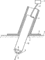
Fig. 3 schematically shows the first embodiment of the present invention, and in this embodiment, the example of property is set up sleeve structure 1 at sea bed 3 as an illustration.Structure 1 is by one or more stakes 10 permanent positions that remain on the sea bed 3, and described stake 10 supporting legs 7 by this structure are installed in the sea bed 3.
For this embodiment of the present invention, stake 10 is dug so that it is penetrated and be positioned in the sea bed 3 by punching.
The stake 10 of this embodiment comprises a plurality of nozzles 8 that are in stake 10 the tip 6, and a plurality of nozzles 8 can form the water jet 9 that the material that makes sea bed 3 eddies, and thus stake to be positioned are produced low resistance.
For another embodiment of the present invention, be responsible for rushing pick so that the material of sea bed 3 eddies by the pick device that rushes outside the stake, that is, with independently rushing the pick device material of sea bed is eddied, and described stake is following closely to penetrate by the material of punching pick.
For each embodiment of the present invention, control described punching pick by the pick control device 11 that rushes that is connected with nozzle 8 via for example one or more flexible pipes 12.Punching pick control device 11 can be integrated in the stake 10 or can be externally.
Therefore, this embodiment of the present invention is characterised in that foundation structure (for example sleeve pipe or tripod) is to be fixed to sea bed by the one or more stakes that are installed in the sea bed by the punching pick.
The advantage of this embodiment is easy foundation.In addition, this installation does not need specialized ships or heavy equipment to install.Even further, for the once mounting process, can operate simultaneously more than a stake, so this procedure section saves time.
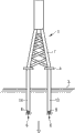
Fig. 4 schematically shows the second embodiment of the present invention.In this embodiment, the example of property is based upon sleeve structure 1 on the sea bed 3 as an illustration.Structure 1 comprise be connected to structure 1(and particularly be connected to the foot 4 that is positioned at supporting leg 7 lower ends) one or more stakes 13.Stake 13 also comprises one or more nozzles 8, and described nozzle 8 has the function that has been described with reference to the first embodiment.
According to a second embodiment of the present invention, stake 13 was connected to structure 1 before being positioned on the sea bed 3.During installation, stake 13 is driven to enter in the sea bed 3 by the punching pick when carrying structure 1.This expression must adjust to each 13 rush pick, in order to shift total onto correct erection position.
Therefore, this embodiment of the present invention is characterised in that it is to realize by utilizing the punching pick that one or more stakes that connected are ordered about to enter in the sea bed that foundation structure (for example sleeve pipe or tripod) is based upon on the sea bed.
The advantage of this embodiment is, total can be installed simultaneously, has minimized thus the time that expensive specialized ships is installed that occupies.
Enter in the sea bed although under the background of sleeve pipe or tripod structure, described by punching pick one or more stakes to be ordered about, but also can be under the background of as shown in Figure 2 single pile structure (for example by using the stake of having described with reference to Fig. 3) finish by the punching pick stake to be ordered about and enter sea bed so that the described single pile structure of grappling.Perhaps, as for sleeve pipe or tripod structure, when stake being ordered about when entering sea bed the independently punching pick device that can use the sea bed material to eddy.
Claims (15)
1. one kind auxiliary is installed in equipment in the sea bed (3) with stake (10,13), and this stake (10,13) will be used to grappling marine basic (1),
It is characterized in that,
Described equipment comprises nozzle (8) and for generation of the device from the water jet (9) of described nozzle (8) ejection.
2. equipment according to claim 1 is characterized in that,
Described equipment comprise be connected with described nozzle (8) rush the pick control device (11).
3. equipment according to claim 2 is characterized in that,
Described punching pick control device (11) is connected with described nozzle by one or more flexible pipes (12).
4. according to claim 1 to one of 3 described equipment, it is characterized in that,
Described integration of equipments is in the described stake (10) that will be used to the marine basis of grappling (1).
5. equipment according to claim 4 is characterized in that,
Described stake (10) comprises tip (6), and the described nozzle (8) of described equipment is arranged in described tip (6).
6. according to claim 2 or 3 described and according to claim 4 or 5 described equipment, it is characterized in that,
Described punching pick control device (11) is integrated in the described stake (10).
7. a marine foundation structure (1), marine basis especially for wind turbine, this sea foundation structure (1) is installed in sea bed (3) upward and comprises at least one foot (4) that described marine foundation structure (1) is anchored on described sea bed and stake (10,13)
It is characterized in that,
Described foundation structure comprises according to claim 1 to one of 6 described equipment.
8. marine foundation structure according to claim 7 is characterized in that,
Described stake (10) is according to claim 4 to one of 6 described stakes.
9. according to claim 7 or 8 described marine foundation structures (1), it is characterized in that,
Described marine foundation structure (1) comprises that at least one has the hollow leg of inner hollow space (7), and described stake (10) is positioned at described hollow space.
10. according to claim 7 or 8 described marine foundation structures, it is characterized in that,
Described marine foundation structure (1) comprises that at least one has the supporting leg of foot (4) (7), and described stake (13) is extended from described foot (4).
11. method of setting up marine basis (1) at sea bed, particularly set up at sea bed and be used for the marine basis that wind turbine is installed, wherein, the marine foundation structure (1) that comprises at least one supporting leg (7) is arranged on the sea bed and by the stake (10,13) that extends to from described supporting leg in the described sea bed (3) and is anchored at the described sea bed (3)
It is characterized in that,
By described stake (10,13) punching is dug in the described sea bed (3) described at least one supporting leg (7) is anchored in the described sea bed (3).
12. method according to claim 11 is characterized in that,
Use marine foundation structure according to claim 9 (1), and after described marine foundation structure (1) has been arranged on the seabed, described stake (10) is dug into the described sea bed (3) from described inner hollow space punching.
13. method according to claim 11 is characterized in that,
Marine foundation structure according to claim 10 (1) utilization is arranged on the described seabed from the extended stake of described at least one foot (13), and described stake (13) punching is dug in the described sea bed (3), and described marine foundation structure (1) utilization is in described at least one foot (4) on the described sea bed (3) and places thus.
14. to one of 13 described methods, it is characterized in that according to claim 11,
Use according to claim 1 to one of the 6 described auxiliary equipment that stake (10,13) is installed described stake punching is dug in the described seabed.
15. method according to claim 14 is characterized in that,
The described auxiliary equipment that stake (10,13) is installed is the autonomous device of the material of the described sea bed of punching pick, and described stake (10,13) is immediately following penetrating after described autonomous device by the material of punching pick.
Applications Claiming Priority (3)
| Application Number | Priority Date | Filing Date | Title |
|---|---|---|---|
| EP10164284.1 | 2010-05-28 | ||
| EP10164284 | 2010-05-28 | ||
| PCT/EP2010/067927 WO2011147484A1 (en) | 2010-05-28 | 2010-11-22 | Device for assisting in installing a pile in the seabed, offshore foundation structure and method of establishing an offshore foundation |
Publications (2)
| Publication Number | Publication Date |
|---|---|
| CN102906339A true CN102906339A (en) | 2013-01-30 |
| CN102906339B CN102906339B (en) | 2015-11-25 |
Family
ID=43530904
Family Applications (2)
| Application Number | Title | Priority Date | Filing Date |
|---|---|---|---|
| CN2010800671059A Pending CN102906340A (en) | 2010-05-28 | 2010-11-05 | Ground anchor, offshore foundation using a ground anchor and method of establishing an offshore foundation |
| CN201080067096.3A Expired - Fee Related CN102906339B (en) | 2010-05-28 | 2010-11-22 | Auxiliary equipment stake is arranged in sea bed, offshore foundation structure and set up the method for offshore foundation |
Family Applications Before (1)
| Application Number | Title | Priority Date | Filing Date |
|---|---|---|---|
| CN2010800671059A Pending CN102906340A (en) | 2010-05-28 | 2010-11-05 | Ground anchor, offshore foundation using a ground anchor and method of establishing an offshore foundation |
Country Status (3)
| Country | Link |
|---|---|
| EP (2) | EP2542722A1 (en) |
| CN (2) | CN102906340A (en) |
| WO (3) | WO2011147482A1 (en) |
Cited By (3)
| Publication number | Priority date | Publication date | Assignee | Title |
|---|---|---|---|---|
| CN106382192A (en) * | 2016-10-27 | 2017-02-08 | 李白 | Offshore wind turbine generator |
| CN109641639A (en) * | 2016-07-27 | 2019-04-16 | 赵炳镐 | A kind of mooring arrangement |
| CN111121730A (en) * | 2020-02-25 | 2020-05-08 | 中国海洋大学 | Bottom boundary layer in-situ observation system suitable for shallow water viscous seabed and arrangement method thereof |
Families Citing this family (16)
| Publication number | Priority date | Publication date | Assignee | Title |
|---|---|---|---|---|
| PT2727813T (en) | 2008-04-23 | 2017-10-26 | Principle Power Inc | Column-stabilized offshore platform with water-entrapment plates and asymmetric mooring system for support of offshore wind turbines |
| GB2501123B (en) * | 2012-04-13 | 2014-09-10 | Laing O Rourke Plc | Foundation structures |
| ES2452933B1 (en) | 2012-10-03 | 2015-03-09 | Tecnica Y Proyectos S A | Gravity foundation system for the installation of offshore wind turbines |
| DK3366567T3 (en) | 2013-05-20 | 2020-01-27 | Principle Power Inc | SYSTEM AND PROCEDURE FOR MANAGING OFFSHORE WINDOW MILLING PLATES |
| CN103423093B (en) * | 2013-09-03 | 2014-12-31 | 上海交通大学 | Platform floating type wind driven generator provided with suction caissons and used for sea surface of deep sea |
| CN103939783B (en) * | 2014-05-05 | 2015-11-04 | 浙江大学 | A kind of suspension column luminescence system based on stretching integral principle |
| PL3212496T3 (en) | 2014-10-27 | 2020-03-31 | Principle Power, Inc. | Connection system for array cables of disconnectable offshore energy devices |
| PL3310647T3 (en) | 2015-06-19 | 2021-08-23 | Principle Power, Inc. | Floating wind turbine platform structure with optimized transfer of wave and wind loads |
| CN105274988B (en) * | 2015-09-10 | 2017-03-01 | 国网山东省电力公司济南供电公司 | A kind of anchor pole of convenient construction |
| JP6575459B2 (en) * | 2016-08-17 | 2019-09-18 | Jfeエンジニアリング株式会社 | Implantable foundation and construction method |
| US11225945B2 (en) | 2019-05-30 | 2022-01-18 | Principle Power, Inc. | Floating wind turbine platform controlled to optimize power production and reduce loading |
| CN112227298B (en) * | 2020-10-21 | 2022-03-11 | 广东华蕴海上风电科技有限公司 | Automatic installation anti-scouring protection device for offshore wind power |
| ES1276849Y (en) * | 2020-12-28 | 2021-11-18 | Nabrawind Tech S L | NEW WIND GENERATOR AND ITS ANCHORS |
| GB2604909A (en) | 2021-03-18 | 2022-09-21 | Subsea 7 Ltd | Subsea foundations |
| JP7223181B1 (en) * | 2022-01-21 | 2023-02-15 | 日鉄エンジニアリング株式会社 | Jacket structure, offshore wind turbine, jacket structure system, and offshore wind turbine system |
| KR102533316B1 (en) * | 2022-11-29 | 2023-05-17 | (주)대창솔루션 | Nodes for offshore wind power substructures manufactured by casting |
Citations (4)
| Publication number | Priority date | Publication date | Assignee | Title |
|---|---|---|---|---|
| US2979910A (en) * | 1955-06-06 | 1961-04-18 | Shell Oil Co | Offshore platform structure and method of erecting same |
| JPS60230430A (en) * | 1984-04-26 | 1985-11-15 | Kinji Kuwabara | Pile driving method |
| US20030072620A1 (en) * | 2001-10-15 | 2003-04-17 | Long Walter Daniel | Jet head device for sinking pilings |
| CN101196005A (en) * | 2006-12-08 | 2008-06-11 | 天津市海恩海洋工程技术服务有限公司 | Drill absorption pile structure and construction method thereof |
Family Cites Families (20)
| Publication number | Priority date | Publication date | Assignee | Title |
|---|---|---|---|---|
| NL39429C (en) * | ||||
| US3262412A (en) * | 1964-11-23 | 1966-07-26 | Paul A Dantz | Pad-lock anchor system |
| FR2070329A5 (en) * | 1969-12-01 | 1971-09-10 | Praet Michel Van | |
| FR2221012A5 (en) * | 1973-03-09 | 1974-10-04 | Shibata Mituo | |
| NL7505256A (en) * | 1975-05-02 | 1976-11-04 | Ballast Orient Contracting Co | Artificial off shore island - with ballast fitted open top vessel as foundation for e.g. oil drilling structure |
| JPS54155607A (en) * | 1978-04-06 | 1979-12-07 | Hisaharu Nakashima | Method of pile driving construction to base rock |
| US5988949A (en) | 1996-01-11 | 1999-11-23 | Mcdermott Int Inc | Offshore jacket installation |
| EP1068403B2 (en) * | 1998-04-02 | 2018-10-10 | SPT Equipment bv | Marine structure |
| CN2451634Y (en) * | 2000-08-09 | 2001-10-03 | 合肥工业大学 | Expansion anchor |
| DE10109428A1 (en) * | 2001-02-27 | 2002-09-05 | Remmer Briese | Off-shore wind turbine |
| DE10222646A1 (en) * | 2001-04-06 | 2004-01-22 | Joachim Falkenhagen | Cable support, for an offshore wind power tower, has additional side cables linking them together to take up the movements and give a damping effect |
| US6764251B1 (en) * | 2001-07-05 | 2004-07-20 | Anthony J. Schnur | Anchor |
| DE10349109B4 (en) * | 2003-10-17 | 2008-02-07 | Aerodyn Engineering Gmbh | Foundation for an offshore wind energy plant |
| DE102004042066B4 (en) | 2004-08-31 | 2006-12-14 | Bard Engineering Gmbh | Foundation for an offshore wind turbine |
| DE102005014868A1 (en) * | 2005-03-30 | 2006-10-05 | Repower Systems Ag | Offshore wind turbine with non-slip feet |
| CN201031391Y (en) * | 2007-05-11 | 2008-03-05 | 南京工业大学 | Umbrella-shape weigh anchor |
| EP2185816B2 (en) | 2007-08-29 | 2021-11-03 | Vestas Offshore Wind A/S | Monopile foundation for offshore wind turbine |
| EP2067915A2 (en) * | 2007-12-04 | 2009-06-10 | WeserWind GmbH | Grid structure for an offshore construction, in particular an offshore wind energy converter |
| EP2067914A2 (en) | 2007-12-04 | 2009-06-10 | WeserWind GmbH | Grid structure for an offshore construction, in particular an offshore wind energy converter, and method for manufacture thereof |
| CN201190283Y (en) * | 2008-03-20 | 2009-02-04 | 辽宁省电力有限公司盘锦供电公司 | Expansion ground anchor |
-
2010
- 2010-11-05 WO PCT/EP2010/066922 patent/WO2011147482A1/en active Application Filing
- 2010-11-05 CN CN2010800671059A patent/CN102906340A/en active Pending
- 2010-11-05 EP EP10776988A patent/EP2542722A1/en not_active Withdrawn
- 2010-11-22 WO PCT/EP2010/067927 patent/WO2011147484A1/en active Application Filing
- 2010-11-22 CN CN201080067096.3A patent/CN102906339B/en not_active Expired - Fee Related
- 2010-11-22 EP EP10784753A patent/EP2536881A1/en not_active Ceased
-
2011
- 2011-01-19 WO PCT/EP2011/050681 patent/WO2011147592A1/en active Application Filing
Patent Citations (4)
| Publication number | Priority date | Publication date | Assignee | Title |
|---|---|---|---|---|
| US2979910A (en) * | 1955-06-06 | 1961-04-18 | Shell Oil Co | Offshore platform structure and method of erecting same |
| JPS60230430A (en) * | 1984-04-26 | 1985-11-15 | Kinji Kuwabara | Pile driving method |
| US20030072620A1 (en) * | 2001-10-15 | 2003-04-17 | Long Walter Daniel | Jet head device for sinking pilings |
| CN101196005A (en) * | 2006-12-08 | 2008-06-11 | 天津市海恩海洋工程技术服务有限公司 | Drill absorption pile structure and construction method thereof |
Cited By (3)
| Publication number | Priority date | Publication date | Assignee | Title |
|---|---|---|---|---|
| CN109641639A (en) * | 2016-07-27 | 2019-04-16 | 赵炳镐 | A kind of mooring arrangement |
| CN106382192A (en) * | 2016-10-27 | 2017-02-08 | 李白 | Offshore wind turbine generator |
| CN111121730A (en) * | 2020-02-25 | 2020-05-08 | 中国海洋大学 | Bottom boundary layer in-situ observation system suitable for shallow water viscous seabed and arrangement method thereof |
Also Published As
| Publication number | Publication date |
|---|---|
| CN102906340A (en) | 2013-01-30 |
| EP2536881A1 (en) | 2012-12-26 |
| WO2011147484A1 (en) | 2011-12-01 |
| WO2011147592A1 (en) | 2011-12-01 |
| CN102906339B (en) | 2015-11-25 |
| WO2011147482A1 (en) | 2011-12-01 |
| EP2542722A1 (en) | 2013-01-09 |
Similar Documents
| Publication | Publication Date | Title |
|---|---|---|
| CN102906339B (en) | Auxiliary equipment stake is arranged in sea bed, offshore foundation structure and set up the method for offshore foundation | |
| CN102362033B (en) | Installing submerged support structures | |
| US8517639B2 (en) | Installation of underwater anchorages | |
| US8689721B2 (en) | Vertically installed spar and construction methods | |
| WO2018129471A1 (en) | Modular offshore wind turbine foundation and modular substructure with suction caissons | |
| KR101687368B1 (en) | Support structure of offshore wind turbines and structure method thereof | |
| EP2574698B1 (en) | Method and device for driving a multiplicity of piles into a seabed | |
| JP2018100578A (en) | Jacket position adjustment mechanism and building method of landing style foundation | |
| AU2006300972B2 (en) | Installation of underwater anchorages | |
| EP3307954B1 (en) | Monopile foundation for an offshore tower structure | |
| JP2016199874A (en) | Removal method of pile foundation, pile foundation and installation method of pile foundation | |
| CN108775022A (en) | Accessory structure and its construction method are integrated suitable for ice formation offshore wind turbine foundation | |
| KR101341176B1 (en) | Offshore pile-type support structure and construction method thereof | |
| WO2012046077A1 (en) | Apparatus and method for the erection of a wind turbine | |
| CN205000333U (en) | Marine wind turbine foundation | |
| WO2013053936A1 (en) | Seabed anchoring system and method for such a system | |
| KR102184891B1 (en) | Partially connected pile hybrid anchor | |
| EP2444313A2 (en) | Anchor with means for securing to sea bed and for facilitating retrieval | |
| KR102247425B1 (en) | Suction pile capable of supplying fluid and Vertical alignment method of the Suction pile | |
| EP2697455B1 (en) | A method of obtaining vertical alignment of a tower | |
| CN114162273A (en) | Independent type marine towing and installation dual-purpose buoyancy adjustable buoy and construction method | |
| KR20140140440A (en) | Hybrid support structure and method for installing the same | |
| CN211340734U (en) | Small offshore rock-socketed platform | |
| EP2558647B1 (en) | Offshore foundation structure, offshore foundation using such a structure and method of establishing an offshore foundation | |
| KR102556184B1 (en) | Offshore structure fixed anchor and anchor method using the same |
Legal Events
| Date | Code | Title | Description |
|---|---|---|---|
| C06 | Publication | ||
| PB01 | Publication | ||
| C10 | Entry into substantive examination | ||
| SE01 | Entry into force of request for substantive examination | ||
| C14 | Grant of patent or utility model | ||
| GR01 | Patent grant | ||
| TR01 | Transfer of patent right |
Effective date of registration: 20190729 Address after: Tango barley Patentee after: Siemens Gamesa Renewable Energy Address before: Munich, Germany Patentee before: Siemens AG |
|
| TR01 | Transfer of patent right | ||
| CF01 | Termination of patent right due to non-payment of annual fee |
Granted publication date: 20151125 Termination date: 20201122 |
|
| CF01 | Termination of patent right due to non-payment of annual fee |