CN102879416B - Experiment device and experiment method for gas cloud combustion, explosion simulation and inerting, inhibition - Google Patents
Experiment device and experiment method for gas cloud combustion, explosion simulation and inerting, inhibition Download PDFInfo
- Publication number
- CN102879416B CN102879416B CN201210364377.6A CN201210364377A CN102879416B CN 102879416 B CN102879416 B CN 102879416B CN 201210364377 A CN201210364377 A CN 201210364377A CN 102879416 B CN102879416 B CN 102879416B
- Authority
- CN
- China
- Prior art keywords
- explosion
- gas
- experiment
- tank
- test container
- Prior art date
- Legal status (The legal status is an assumption and is not a legal conclusion. Google has not performed a legal analysis and makes no representation as to the accuracy of the status listed.)
- Active
Links
Images


Abstract
The invention relates to the technical field of fire hazard safety, and especially relates to an experiment device and an experiment method for gas cloud combustion, explosion simulation and inerting, inhibition. The device comprises an experiment test system composed of an explosion experiment container tank, a flame and explosion pressure radial propagation detection device, an ignition device, a generated gas sampling analyzer, and a high-speed schlieren and data acquisition, a sample introduction system, a combustion explosion inerting inhibition system, and a control system composed of wireless synchronous control and computer remote monitoring, and is a multifunctional comprehensive experiment platform device. The invention realizes 180-degree rotation of the tank, data synchronous acquisition, gas distribution and sample introduction with precise proportions, synchronous and delayed multimode ignition and inhibition system ejection; wireless and wired data transmission is adopted for control; man-machine separation of the tank and the controlling person is realized; safety and reliability of data transmission are guaranteed; combustion or explosion and inerting and inhibition experiments of various experiment samples such as gas cloud, dust, oil mist, and the like can be carried out when the tank is in a vertical or horizontal state.
Description
Technical field
The present invention relates to fire safety evaluating technical field, particularly a kind of gas cloud burning, blast analogue and inerting, inhibition experimental provision and experimental technique.
Background technology
Flammable premix gas, dust, liquid mist steam fire, explosion accident are disaster accident types common in the industrial fire such as petrochemical complex, explosion accident, about gas cloud, dust, liquid mist fire/explosion feature, Evolution and fire extinguishing thereof, explosion-proof, datonation-inhibition technology are the focuses of industrial fire blast Study of Prevention Technology.People adopt the experimental provisions such as flame propagation pipe, shock tube, explosive container or simulation tunnel conventionally to flammable vapor cloud, dust combustion, blast characteristics research at present.At present China's dust cloud explosion property and explosion limits test analysis national standard mainly contain GB/T16425, GB/T16426 and GB/T12474, and its experiment test mainly adopts the spherical explosive container of 20L, 1 cube of column type explosive container and pipe burner.For the burning of gas cloud and explosive flame, suppress, people adopt the experimental provisions such as flame propagation pipe or simulation tunnel conventionally, by observing the characteristic parameters such as flame propagation process and explosive flame temperature, pressure study.And the comprehensive experiment method and the device that still for inerting, burning or the explosive flame of flammable vapor cloud, dust and mist of oil steam, do not suppress at present.
Summary of the invention
The object of the invention is for different samples such as flammable vapor cloud, dust and mist of oil steam, research and develop a kind of flammable vapor cloud, dust and the burning of mist of oil steam, blast analogue and carry out device and the experimental technique of inerting, explosive flame inhibition experiment.Adopt the present invention can meet different oxygen concentrations, different sparking mode and ignition energy condition, multi-form flammable vapor cloud burning, the test of blast characteristic parameter, the demands such as the experimental studies such as burning, blast inerting and inhibition evaluation and the detection of inerting inhibition system, therefore, this device is a kind of multifunctional comprehensive experiment porch device.
The technical scheme that the present invention takes is for achieving the above object: a kind of gas cloud burning, blast analogue and inerting, suppress experimental provision, it is characterized in that: comprise experiment and test macro, sampling system, combustion explosion suppresses system and test control system four parts, experiment comprises explosion test container tank with test macro, flame and explosion pressure radial propagation pick-up unit, portfire, generate gas sampling analyser, the high speed schlieren system and the data acquisition system (DAS) that by high-speed camera and schlieren, are formed, test control system comprises wireless synchronization control system and computer remote monitoring system, described explosion test container tank is right cylinder, cylindrical upper and lower both ends of the surface are spherical, in cylindrical both sides, rotating mechanism is installed, on two spherical end surfaces, be separately installed with manhole flange and lower manhole flange, and by upper manhole flange and lower manhole flange, top manhole cover and bottom manhole cover are installed respectively, manhole cover center, top is provided with flange seat, the common interface that suppresses system for connecting combustion explosion is installed on flange seat, sample introduction flange for connecting sampling system is installed in the center of bottom manhole cover, gas sampling mouth for connecting sampling system is also installed simultaneously on the manhole cover of bottom, in both side surface center, the front and back of explosion test container tank, by mounting flange, be symmetrically installed with the view window for high-speed photography and the observation of penetration schlieren respectively, along explosion test container tank tank body vertical axes to being provided with sensor mounting flange, sets of temperature sensors is fixed on sensor mounting flange and with data acquisition system (DAS) and is connected with pressure transducer group, described portfire is radially arranged on the center of explosion test container tank by mounting flange, described flame and explosion pressure radial propagation pick-up unit are arranged on the center of explosion test container tank by mounting flange, and radially towards the incendiary source position of portfire, and be connected with data acquisition system (DAS), the described high speed schlieren system consisting of high-speed camera and schlieren is fixed on the position with respect to described view window, described generation gas sampling analyser is connected on the thieff hatch of explosion test container tank, and be connected with data acquisition system (DAS), data acquisition system (DAS) is connected with computer remote monitoring system by wireless synchronization control system.
The experimental technique of gas cloud of the present invention burning, blast analogue and inerting, inhibition experimental provision comprises the following steps:
(1). first utilize vacuum pump in explosion test container tank, to vacuumize, according to experiment, the inflammable gas of laboratory sample and oxygen need to be filled with in explosion test container tank by matched proportion density volume ratio respectively, utilize high velocity air fully to mix in explosion test container tank; Or by the combustible dust of experiment or can fuel material sample utilize pressurized air to spurt in explosion test container tank and form flammable vapor cloud at a high speed;
(2). when carrying out the burning of gas cloud or explosion test, according to the kind of gas cloud combustible material, select corresponding sparking mode and ignition energy, utilize pulse firing, chemic ignition or thermo-fuse sparking mode to light a fire to flammable vapor cloud, and adjust pulse firing energy by regulating impulse ignition voltage, realize different-energy igniting, utilize temperature, pressure transducer test burning or explosive flame temperature and explosion test container tank internal pressure to change;
(3). when carrying out explosive flame inhibition experiment, utilize as required wireless synchronization control system while or delay start portfire and inhibition system, by view window, observe burning or explosion suppression experimentation phenomenon, utilize test system and test to record relevant feature parameters;
(4). when carrying out flammable vapor cloud inerting experiment, in the explosion test container tank of the flammable vapor cloud that distributes, time delay or synchronously spurt the inerting inhibitor of respective concentration, adopt different-energy or sparking mode to carry out positive ignition, by the experimental observation of view window and test macro, inhibitor inerting inhibition is carried out to evaluation analysis.
The beneficial effect that the present invention produces is: realized test macro, sampling system and inhibition system and by wireless synchronization control system, carried out centralized control respectively; Wireless synchronization control system comprises by the attainable major function of computer remote monitoring system: the lifting rotation of tank body, multipath synchronous data collection, synchronous and late ignition, accurate ratio distribution with sample introduction, synchronize and postpone inhibition system and spurt; Control system adopts wireless and wired two kinds of data transfer modes, can realize the separate men from machines of tank body and control system, ensures the safe and reliable of data transmission simultaneously.In tank body center, be symmetrically installed with rotating mechanism, for realizing tank body 180 degree rotations, to carry out different burnings or blast and inerting thereof at the horizontal or vertical state of tank body, suppress experiment, also facilitate tank body install, clean and safeguard simultaneously.
Accompanying drawing explanation
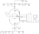
Fig. 1 is this experimental provision Functional Design schematic diagram.
Fig. 2 is experimental provision structure front schematic view.
Fig. 3 is explosion test container tank structure schematic top plan view.
Fig. 4 is that combustion explosion inhibition system forms connection diagram.
Fig. 5 is that sampling system forms connection diagram.
Fig. 6 is rotating mechanism structural representation.
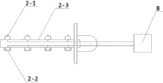
Fig. 7 is flame and explosion pressure radial propagation structure of the detecting device schematic diagram.
Fig. 8 is retractable electrode ignition device structure schematic diagram.
Fig. 9 is pulse firing cell operation schematic diagram.
Figure 10 is chemic ignition cell arrangement structural representation.
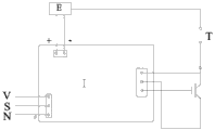
Figure 11 chemic ignition/thermo-fuse ignition control circuit figure.
Figure 12 is wireless synchronization control system fundamental diagram.
Figure 13 is data acquisition system (DAS) fundamental diagram.
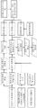
Figure 14 is this experimental provision experiment flow figure.
Embodiment
Below in conjunction with accompanying drawing, the invention will be further described.
With reference to Fig. 1, Fig. 2 and Fig. 3, the burning of gas cloud, blast analogue and inerting, suppress experimental provision and comprise experiment and test macro, sampling system, combustion explosion suppresses system and control system four parts, experiment comprises explosion test container tank 1 with test macro, flame and explosion pressure radial propagation pick-up unit 2, portfire 3, generate gas sampling analyser 4, the high speed schlieren system 7 being formed by high-speed camera and schlieren and data acquisition system (DAS) 8, control system comprises wireless synchronization control system 9 and computer remote monitoring system 10, explosion test container tank 1 is right cylinder, cylindrical upper and lower both ends of the surface are spherical, in cylindrical both sides, rotating mechanism Z is installed, on two spherical end surfaces, be separately installed with manhole flange 1-1 and lower manhole flange 1-2, and by upper manhole flange 1-1 and lower manhole flange 1-2, top manhole cover 1-3 is installed respectively and bottom manhole cover 1-4(can change), manhole cover 1-3 center, top is provided with flange seat 1-5, the common interface 1-6 that suppresses system for connecting combustion explosion is installed on flange seat 1-5, sample introduction flange 1-7 for connecting sampling system is installed in the center of bottom manhole cover 1-4, gas sampling mouth 1-8 for connecting sampling system is also installed simultaneously on the manhole cover 1-4 of bottom, by this gas sampling mouth, can realize explosion test container tank 1 is vacuumized and accurate ratio distribution in tank body, in both side surface center, the front and back of explosion test container tank 1, by mounting flange, be symmetrically installed with the heavy caliber pressure resistant quartz glass window 1-9 for high-speed photography and the observation of penetration schlieren respectively, along explosion test container tank 1 tank body vertical axes to being provided with five sensor mounting flange 1-10, five temperature sensors of sets of temperature sensors 8-1() with five pressure transducers of pressure transducer group 8-2() to be separately fixed at sensor mounting flange 1-10 upper and be connected with data acquisition system (DAS) 8, portfire 3 is radially arranged on the center of explosion test container tank 1 by mounting flange, flame and explosion pressure radial propagation pick-up unit 2 are arranged on the center of explosion test container tank 1 by mounting flange, and radially towards the incendiary source position of portfire 3, and be connected with data acquisition system (DAS) 8, the high speed schlieren system 7 consisting of high-speed camera and schlieren is fixed on the position with respect to described view window 1-9, generating gas sampling analyser 4 is connected on the thieff hatch of explosion test container tank 1, and be connected with data acquisition system (DAS) 8, data acquisition system (DAS) 8 is connected with computer remote monitoring system 10 by wireless synchronization control system 9.At the diverse location of inner tank wall face, be provided with installation of sensors flange, can be used for installation and the experiment test of the number of different types sensors such as temperature, pressure.
With reference to Fig. 7, flame and explosion pressure radial propagation pick-up unit 2 comprise temperature sensor or flame sensor 2-1, pressure transducer 2-2, the scalable loop bar 2-3 of sensor, wherein temperature sensor or flame sensor 2-1 and pressure transducer 2-2 are arranged on respectively on the upper and lower surfaces of same position of scalable loop bar 2-3, and each sensing data transfer wire is connected with data acquisition system (DAS) 8 by the mounting flange in explosion test container tank 1 by scalable loop bar 2-3 is inner.
With reference to Fig. 8, portfire 3 is retractable electrode portfires, comprise spark electrode 3-1, telescopic 3-2, electrode stem 3-3, insulation course 3-4, spark electrode cap 3-5, clamping cap 3-6 and ignition lead 3-7, wherein spark electrode 3-1 is connected and is arranged in telescopic 3-2 with electrode stem 3-3 by electrode holding screw 3-8, insulation course 3-4 is coated on electrode stem 3-3, and utilizing clamping cap 3-6 to be fixed on the tank flange of explosion test container tank 1, ignition lead 3-7 is fixed on electrode stem 3-3 by spark electrode cap 3-5 and goes up and draw.When experiment material need to adopt chemic ignition, the upper electrode stem 3-3 ignition lead 3-7 being connected with spark electrode 3-1 need be replaced by chemic ignition unit; When experiment material need to adopt steady temperature igniting, ignition lead 3-7 need be replaced by thermo-fuse igniting unit.
With reference to Fig. 9, the pulse firing unit being connected with retractable electrode portfire is by photoelectrical coupler, D.C. regulated power supply, pulse producer, IGBT driver module, inverse-excitation type high-voltage pulse module composition, during its work, ignition signal is worked through photoelectrical coupler starting impulse generator, the pulse of pulse producer output is input to IGBT driver module, in the armature winding of inverse-excitation type pulse module, produce stable pulse current, in the secondary winding of inverse-excitation type pulse module, form high-voltage pulse simultaneously, high-voltage pulse is through the spray point electric discharge of scalable spark electrode, realize pulse firing, while adjusting the energy of pulse firing as need, only need to adjust the input voltage of pulse firing D.C. regulated power supply.
With reference to Figure 10; chemic ignition unit is comprised of control circuit 3-7-1, substrate 3-7-2, thermo-fuse 3-7-3, phosphor coating 3-7-4, gunpowder 3-7-5, protective seam 3-7-6; during its work, by ignition signal Drive and Control Circuit 3-7-1, make rapidly thermo-fuse 3-7-3 fuse; the energy that high temperature thermo-fuse fusing the produces phosphor coating 3-7-4 that ignites immediately; its burning produce power gunpowder 3-7-5 that ignites rapidly; the energy that gunpowder produces makes protective seam 3-7-6 instant exploding, forms divergent contour chemic ignition.
Thermo-fuse igniting unit is comprised of two extraction electrodes and thermo-fuse, thermo-fuse consists of the filament of different melting points, ignition signal makes electric current pass through thermo-fuse through control circuit 3-7-1, by the electric current of thermo-fuse, the temperature of thermo-fuse is raise fast, thermo-fuse fracture when thermo-fuse temperature reaches the fusing point that forms thermo-fuse material, can form the thermo-fuse igniting of different temperatures.
With reference to Figure 11, chemic ignition/thermo-fuse ignition control circuit comprises IGBT driver module I; Switching Power Supply E; Chemic ignition unit/thermo-fuse igniting unit terminals T, control signal public power terminals V, ignition signal input end S and signal are inputted public negative terminal N.Ignition signal is input to IGBT drive plate, through photoelectricity isolated variable, become IGBT to drive signal, control the conducting of IGBT high speed, initial firing current transient flow is crossed thermo-fuse, hot melt wire fusing when thermo-fuse temperature reaches melting temperature, thermo-fuse fusing-off temperature also can the ignite phosphor coating 3-7-4 of chemic ignition unit simultaneously.
With reference to Fig. 5, sampling system comprises air compressor machine 5-1, high-pressure gas cylinder 5-2, stop valve 5-3, high-pressure solenoid valve 5-4, sample high pressure storage tank 5-5, the first pneumatic valve 5-6, accurate distribution flowmeter 5-7, vacuum pump bidirectional protective solenoid electric valve 5-8, vacuum pump 5-9 and fan diffuser 5-10, wherein fan diffuser 5-10 is placed in explosion test container tank 1 inner bottom part by sample introduction flange 1-7, fan diffuser 5-10 is connected with sample high pressure storage tank 5-5 by the first pneumatic valve 5-6, sample high pressure storage tank 5-5 is connected with high-pressure gas cylinder 5-2 with stop valve 5-3 by high-pressure solenoid valve 5-4, high-pressure gas cylinder 5-2 is connected with air compressor machine 5-1, vacuum pump 5-9 is connected with described gas sampling mouth 1-8 by vacuum pump bidirectional protective solenoid electric valve 5-8, accurate distribution flowmeter 5-7 is arranged on pipeline.
By this sampling system, can realize respectively or simultaneously gas, dust, liquid separately or mix fast sample, and in tank, spurting formation gas cloud.Sample high pressure storage tank internal memory is placed with powder/fluid sample and gases at high pressure, by wireless synchronization control system 9, open the first pneumatic valve, gases at high pressure carry powder secretly or fluid sample sprays at a high speed explosion test container tank by pipeline, swiftly flowing sample clashes into the effect of fan diffuser through different angles reflecting surface, realizes sample evenly diffusion at a high speed.
With reference to Fig. 4, combustion explosion inhibition system comprises fluid reservoir 6-1, water smoke control solenoid valve 6-2, hydraulic pamp 6-3, the second pneumatic valve 6-4, dry powder control solenoid valve 6-5, dry powder inhibitor storage tank 6-6, pressure gas control solenoid valve 6-7, high pressure tank 6-8, gas control solenoid valve 6-9, gas extinguishing agent high-pressure gas cylinder 6-10 and inhibitor shower nozzle/powder fan diffuser 6-11, wherein shower nozzle/powder fan diffuser 6-11 is placed in explosion test container tank 1 by described common interface 1-6, the second pneumatic valve 6-4 is connected with shower nozzle/powder fan diffuser 6-11, the second pneumatic valve 6-4 is connected with hydraulic pamp 6-3 by water smoke control solenoid valve 6-2, hydraulic pamp 6-3 is connected with fluid reservoir 6-1, the second pneumatic valve 6-4 is connected with dry powder inhibitor storage tank 6-6 by dry powder control solenoid valve 6-5, dry powder inhibitor storage tank 6-6 is connected with high pressure tank 6-8 by pressure gas control solenoid valve 6-7, the second pneumatic valve 6-4 is connected with gas extinguishing agent high-pressure gas cylinder 6-10 by gas control solenoid valve 6-9 again.
The second high speed pneumatic valve is connected from different restraining devices with control solenoid valve by four-way connector, can realize spurting respectively and spurting simultaneously of the different inhibitor of water smoke restraining device, dry powder restraining device and gas restraining device; Wherein water smoke restraining device mainly spurts solenoid electric valve by fluid reservoir, hydraulic pamp, water smoke and waterfog head forms, dry powder restraining device is mainly comprised of parts such as dry powder inhibitor storage tank, high pressure tank, dry powder control solenoid valve and dry powder jet pipes, and gas restraining device is mainly comprised of gas extinguishing agent high-pressure gas cylinder, gas control solenoid valve and gas inhibitor shower nozzle.By controlling the switch of the switch of the second high speed pneumatic valve and dry powder control solenoid valve, water smoke control solenoid valve, gas control solenoid valve, can realize different inhibitor fire extinguishing and inerting single or hybrid mode and suppress experiment.
With reference to Fig. 6, rotating mechanism Z comprises turning axle Z-1, fixed sleeve of rotating shaft Z-2, bearing holder (housing, cover) Z-3, shaft joint Z-4, bipolar turbine worm reducer Z-5, level Four reducing motor Z-6 and lifting machine supporting plate Z-7, wherein fixed sleeve of rotating shaft Z-2 axle center is welded on described explosion test container tank 1 both sides relatively, both sides turning axle Z-1 is arranged on lifting machine supporting plate Z-7 by bearing holder (housing, cover) Z-3 respectively, one sidespin rotating shaft Z-1 is connected with bipolar turbine worm reducer Z-5 output shaft by shaft joint Z-4, the output shaft of level Four reducing motor Z-6 is connected with the input shaft of bipolar whirlpool worm decelerating machine Z-5.
Rotating mechanism Z is used for realizing the 180 degree rotations of explosion test tank body of container, to carry out different burnings or explosion suppression experiment at the horizontal or vertical state of tank body, also facilitates tank body install, clean and safeguard simultaneously; Whole tank body by the rotating mechanism of both sides be arranged on can synchronization lifting leading screw or hydraulic pressure lift that to lift device J upper, can realize synchronous lifting and decline; Location locking device 1-11 is installed on tank body sample introduction flange 1-7 end face, and a sidespin rotating shaft Z-1 is provided with worm and gear rotary self-locking device Z-8.
Explosion test container tank 1 is provided with thieff hatch, generates gas sampling analyser 4 and collects experiment generation gas by the reduction valve on thieff hatch.Pressure relief safety valve is also installed in explosion test container tank 1.
Referring to Figure 12, wireless synchronization control system 9 comprises receiving antenna, radio frequency amplification and modulation/demodulation modules, FSK keying coding/decoding module, central processing unit, general com interface and Switching Power Supply.Data receiver is inputted FSK keying coding/decoding module by the carrier signal of antenna reception and is decoded after radio frequency amplification and modulation/demodulation modules circuit amplification processing, the Transistor-Transistor Logic level signal that changes standard after central processing unit is processed into, is transferred to master control system by general com interface; Data send by master control system the data of needs transmission are transferred to central processing unit by general com interface, after data processing, being transferred to FSK keying coding/decoding module encodes, through radio frequency amplification and modulation/demodulation modules, carry out after signal modulation, by antenna transmission.Computer remote monitoring system 10 comprises master control system, wireless energy control units, computer monitoring module and related software.Wireless energy control units comprises that antenna, radio frequency amplify and modulation/conciliation module, FSK keying coding/decoding module, central processing unit, general com interface and Switching Power Supply.
With reference to Figure 13, data acquisition system (DAS) 8 comprises multi way temperature, pressure transducer, sample circuit, high-speed synchronous A/D change-over circuit, central processing unit and the data-carrier store in tank body, and the sensor voltage by unit separately, the synchronous conversion of current signal are also carried out exchanges data with central processing unit and master control system.
With reference to Figure 14, the concrete experiment flow of this experimental provision is: first carry out preparing before the each system experimentation of experimental provision, portfire, inhibition system, experiment and test macro and set-up of control system, in duty, are determined to explosion test container tank 1 is in testing required horizontal or vertical state; Laboratory sample is prepared (combustible dust or fuel oil), by combustible dust or can add in sample high pressure storage tank 5-5 by fuel material sample, close stop valve 5-3, utilize air compressor machine 5-1 to provide the pressure gas of certain pressure for high-pressure gas cylinder 5-2, and open stop valve 5-3 and high-pressure solenoid valve 5-4 and provide pressure gas for sample high pressure storage tank 5-5.During experiment sample introduction, first open vacuum pump bidirectional protective solenoid electric valve 5-8, utilize vacuum pump 5-9 by gas sampling mouth 1-8, explosion test container tank 1 to be vacuumized.After pressure transducer 2-2 detects that the vacuum tightness of the demand of reaching requires, stop vacuumizing, close vacuum pump bidirectional protective solenoid electric valve 5-8 and vacuum pump 5-9.According to experiment, the inflammable gas of the laboratory sample in sample high pressure storage tank 5-5 and oxygen need to be filled with in explosion test container tank 1 by matched proportion density volume ratio respectively by accurate distribution flowmeter 5-7 and gas injection port 1-8, utilize high velocity air fully to mix in explosion test container tank 1; Or the first high speed pneumatic valve 5-6 of unlatching sampling system, by the combustible dust in sample high pressure storage tank 5-5 or can fuel material sample utilize pressurized air and fan diffuser 5-10 spurts in explosion test container tank 1 at a high speed, carry out flammable liquid atomization or combustible dust and evenly spread, and then form flammable vapor cloud.
When carrying out the burning of gas cloud or explosion test, according to the kind of gas cloud combustible material, select corresponding sparking mode and ignition energy, utilize pulse firing, chemic ignition or thermo-fuse sparking mode are lighted a fire to flammable vapor cloud, utilize the sets of temperature sensors 8-1 of tank internal face, temperature and explosion test container tank internal pressure that pressure transducer group 8-2 can test longitudinal burning or explosive flame wave front change, utilize flame and the explosion pressure radial propagation pick-up unit 2 can be to the temperature of axial burning or explosive flame wave front, pressure is tested, utilize high speed schlieren system 7 to observe igniting and flame propagation process by big viewport, according to experiment, need the delay time of setting, wireless synchronization control system control portfire 3 is carried out gas cloud/oil mist combustion, blast analogue simultaneously.
When carrying out explosive flame inhibition experiment, utilize as required wireless synchronization control system while or delay start portfire and inhibition system, utilize high speed schlieren system 7 to observe burning or explosion suppression experimentation phenomenon by big viewport, utilize test system and test to record relevant feature parameters; According to experiment needs, can start respectively or simultaneously gas restraining device (gas control solenoid valve 6-9 and gas extinguishing agent high-pressure gas cylinder 6-10), dry powder restraining device (dry powder control solenoid valve 6-5, dry powder inhibitor storage tank 6-6, pressure gas control solenoid valve 6-7 and high pressure tank 6-8) and water smoke restraining device (fluid reservoir 6-1, water smoke control solenoid valve 6-2 and hydraulic pamp 6-3), and by the second pneumatic valve 6-4, the inhibitor in dry powder inhibitor storage tank 6-6 be spurted explosion test container tank 1 is interior fast by inhibitor shower nozzle/powder fan diffuser 6-11.
When carrying out flammable vapor cloud inerting experiment, utilize as required wireless synchronization control system to start the corresponding system and device that suppresses, open the second pneumatic valve 6-4 and spurt certain density inhibitor to being uniformly distributed in the explosion test container tank 1 of flammable vapor cloud, start the portfire 3 of corresponding energy simultaneously, the flammable vapor cloud that is uniformly distributed in explosion test container tank 1 is carried out to positive ignition, utilize high speed schlieren system 7 to observe igniting whether occur the experimental phenomenas such as burning or blast by big viewport; Utilize experiment and test system and test to record relevant feature parameters simultaneously, evaluate the inhibitor inerting inhibition of this concentration.
Claims (7)
1. a gas cloud burning, blast analogue and inerting, suppress experimental provision, it is characterized in that: comprise experiment and test macro, sampling system, combustion explosion suppresses system and control system four parts, experiment comprises explosion test container tank (1) with test macro, flame and explosion pressure radial propagation pick-up unit (2), portfire (3), generate gas sampling analyser (4), the high speed schlieren system (7) being formed by high-speed camera and schlieren and data acquisition system (DAS) (8), control system comprises wireless synchronization control system (9) and computer remote monitoring system (10), described explosion test container tank (1) is right cylinder, cylindrical upper and lower both ends of the surface are spherical, rotating mechanism (Z) is installed in cylindrical both sides, on two spherical end surfaces, be separately installed with manhole flange (1-1) and lower manhole flange (1-2), and by upper manhole flange (1-1) and lower manhole flange (1-2), top manhole cover (1-3) and bottom manhole cover (1-4) are installed respectively, top manhole cover (1-3) center is provided with flange seat (1-5), the common interface (1-6) that suppresses system for connecting combustion explosion is installed on flange seat (1-5), sample introduction flange (1-7) for connecting sampling system is installed in the center of bottom manhole cover (1-4), gas sampling mouth (1-8) for connecting sampling system is also installed simultaneously on bottom manhole cover (1-4), both side surface center, front and back in explosion test container tank (1) is symmetrically installed with the view window (1-9) for high-speed photography and the observation of penetration schlieren by mounting flange respectively, along explosion test container tank (1) tank body vertical axes to being provided with sensor mounting flange (1-10), sets of temperature sensors (8-1) is fixed on sensor mounting flange (1-10) above and is connected with data acquisition system (DAS) (8) with pressure transducer group (8-2), described portfire (3) is radially arranged on the center of explosion test container tank (1) by mounting flange, described flame and explosion pressure radial propagation pick-up unit (2) are arranged on the center of explosion test container tank (1) by mounting flange, and radially towards the incendiary source position of portfire (3), and be connected with data acquisition system (DAS) (8), the described high speed schlieren system (7) consisting of high-speed camera and schlieren is fixed on the position with respect to described view window (1-9), described generation gas sampling analyser (4) is connected to by reduction valve on the thieff hatch of explosion test container tank (1), and be connected with data acquisition system (DAS) (8), data acquisition system (DAS) (8) is connected with computer remote monitoring system (10) by wireless synchronization control system (9).
2. gas cloud burning according to claim 1, blast analogue and inerting, suppress experimental provision, it is characterized in that: described flame and explosion pressure radial propagation pick-up unit (2) comprise temperature sensor or flame sensor (2-1), pressure transducer (2-2), the scalable loop bar of sensor (2-3), wherein temperature sensor or flame sensor (2-1) and pressure transducer (2-2) are arranged on respectively on the upper and lower surfaces of same position of scalable loop bar (2-3), each sensing data transfer wire is connected with data acquisition system (DAS) (8) by the mounting flange in explosion test container tank (1) by scalable loop bar (2-3) is inner.
3. gas cloud burning according to claim 1, blast analogue and inerting, suppress experimental provision, it is characterized in that: described portfire (3) is retractable electrode portfire, comprise spark electrode (3-1), telescopic (3-2), electrode stem (3-3), insulation course (3-4), spark electrode cap (3-5), clamping cap (3-6) and ignition lead (3-7), wherein spark electrode (3-1) is connected and is arranged in telescopic (3-2) with electrode stem (3-3), insulation course (3-4) is coated on electrode stem (3-3), and utilize clamping cap (3-6) to be fixed on the mounting flange of explosion test container tank (1), ignition lead (3-7) is fixed on electrode stem (3-3) by spark electrode cap (3-5) and goes up and draw.
4. gas cloud burning according to claim 1, blast analogue and inerting, suppress experimental provision, it is characterized in that: described sampling system comprises air compressor machine (5-1), high-pressure gas cylinder (5-2), stop valve (5-3), high-pressure solenoid valve (5-4), sample high pressure storage tank (5-5), the first pneumatic valve (5-6), accurate distribution flowmeter (5-7), vacuum pump bidirectional protective solenoid electric valve (5-8), vacuum pump (5-9) and fan diffuser (5-10), wherein fan diffuser (5-10) is placed in explosion test container tank (1) inner bottom part by described sample introduction flange (1-7), fan diffuser (5-10) is connected with sample high pressure storage tank (5-5) by the first pneumatic valve (5-6), sample high pressure storage tank (5-5) is connected with high-pressure gas cylinder (5-2) with stop valve (5-3) by high-pressure solenoid valve (5-4), high-pressure gas cylinder (5-2) is connected with air compressor machine (5-1), vacuum pump (5-9) is connected with described gas sampling mouth (1-8) by vacuum pump bidirectional protective solenoid electric valve (5-8), accurate distribution flowmeter (5-7) is arranged on pipeline.
5. gas cloud burning according to claim 1, blast analogue and inerting, suppress experimental provision, it is characterized in that: described combustion explosion inhibition system comprises fluid reservoir (6-1), water smoke control solenoid valve (6-2), hydraulic pamp (6-3), the second pneumatic valve (6-4), dry powder control solenoid valve (6-5), dry powder inhibitor storage tank (6-6), pressure gas control solenoid valve (6-7), high pressure tank (6-8), gas control solenoid valve (6-9), gas extinguishing agent high-pressure gas cylinder (6-10) and shower nozzle/powder fan diffuser (6-11), wherein shower nozzle/powder fan diffuser (6-11) is placed in explosion test container tank (1) by described common interface (1-6), the second high speed pneumatic valve (6-4) is connected with shower nozzle/powder fan diffuser (6-11), the second pneumatic valve (6-4) is connected with hydraulic pamp (6-3) by water smoke control solenoid valve (6-2), hydraulic pamp (6-3) is connected with fluid reservoir (6-1), the second pneumatic valve (6-4) is connected with dry powder inhibitor storage tank (6-6) by dry powder control solenoid valve (6-5), dry powder inhibitor storage tank (6-6) is connected with high pressure tank (6-8) by pressure gas control solenoid valve (6-7), the second pneumatic valve (6-4) is connected with gas extinguishing agent high-pressure gas cylinder (6-10) by gas control solenoid valve (6-9) again.
6. gas cloud burning according to claim 1, blast analogue and inerting, suppress experimental provision, it is characterized in that: described rotating mechanism (Z) comprises turning axle (Z-1), fixed sleeve of rotating shaft (Z-2), bearing holder (housing, cover) (Z-3), shaft joint (Z-4), bipolar turbine worm reducer (Z-5), level Four reducing motor (Z-6) and lifting machine supporting plate (Z-7), wherein fixed sleeve of rotating shaft (Z-2) axle center is welded on described explosion test container tank (1) both sides relatively, both sides turning axle (Z-1) is arranged on lifting machine supporting plate (Z-7) by bearing holder (housing, cover) (Z-3) respectively, one sidespin rotating shaft (Z-1) is connected with bipolar turbine worm reducer (Z-5) output shaft by shaft joint (Z-4), the output shaft of level Four reducing motor (Z-6) is connected with the input shaft of bipolar whirlpool worm decelerating machine (Z-5).
7. gas cloud burning, blast analogue and the inerting of use as described in claim 1-6 any one, an experimental technique for inhibition experimental provision, is characterized in that comprising the following steps:
(1). first utilize vacuum pump in explosion test container tank, to vacuumize, according to experiment, the inflammable gas of laboratory sample and oxygen need to be filled with in explosion test container tank by matched proportion density volume ratio respectively, utilize high velocity air fully to mix in explosion test container tank; Or by the combustible dust of experiment or can fuel material sample utilize pressurized air to spurt in explosion test container tank and form flammable vapor cloud at a high speed;
(2). when carrying out the burning of gas cloud or explosion test, according to the kind of gas cloud combustible material, select corresponding sparking mode and ignition energy, utilize pulse firing, chemic ignition or thermo-fuse sparking mode to light a fire to flammable vapor cloud, and adjust pulse firing energy by regulating impulse ignition voltage, realize different-energy igniting, utilize temperature, pressure transducer test burning or explosive flame temperature and explosion test container tank internal pressure to change;
(3). when carrying out explosive flame inhibition experiment, utilize as required wireless synchronization control system while or delay start portfire and combustion explosion to suppress system, by view window, observe burning or explosion suppression experimentation phenomenon, utilize experiment and test system and test to record relevant feature parameters;
(4). when carrying out flammable vapor cloud inerting experiment, in the explosion test container tank of the flammable vapor cloud that distributes, time delay or synchronously spurt the inerting inhibitor of respective concentration, adopt different-energy or sparking mode to carry out positive ignition, by the experimental observation of view window and experiment and test macro, inhibitor inerting inhibition is carried out to evaluation analysis.
Priority Applications (1)
| Application Number | Priority Date | Filing Date | Title |
|---|---|---|---|
| CN201210364377.6A CN102879416B (en) | 2012-09-26 | 2012-09-26 | Experiment device and experiment method for gas cloud combustion, explosion simulation and inerting, inhibition |
Applications Claiming Priority (1)
| Application Number | Priority Date | Filing Date | Title |
|---|---|---|---|
| CN201210364377.6A CN102879416B (en) | 2012-09-26 | 2012-09-26 | Experiment device and experiment method for gas cloud combustion, explosion simulation and inerting, inhibition |
Publications (2)
| Publication Number | Publication Date |
|---|---|
| CN102879416A CN102879416A (en) | 2013-01-16 |
| CN102879416B true CN102879416B (en) | 2014-04-23 |
Family
ID=47480821
Family Applications (1)
| Application Number | Title | Priority Date | Filing Date |
|---|---|---|---|
| CN201210364377.6A Active CN102879416B (en) | 2012-09-26 | 2012-09-26 | Experiment device and experiment method for gas cloud combustion, explosion simulation and inerting, inhibition |
Country Status (1)
| Country | Link |
|---|---|
| CN (1) | CN102879416B (en) |
Families Citing this family (35)
| Publication number | Priority date | Publication date | Assignee | Title |
|---|---|---|---|---|
| CN103104479A (en) * | 2013-01-28 | 2013-05-15 | 神华集团有限责任公司 | Jacket liquid sulfur pump assembly |
| CN103364531B (en) * | 2013-07-17 | 2015-09-30 | 中北大学 | Flammable liquid steam fires, datonation-inhibition characteristic test system |
| CN103592332B (en) * | 2013-11-27 | 2015-07-15 | 上海化工研究院 | Airbag external-pressurization type mixed gas blasting determination apparatus |
| CN103646143B (en) * | 2013-12-17 | 2016-04-06 | 辽宁石油化工大学 | A kind of method of LPG storage tank coating protection system performance analysis under fire hazard environment |
| CN103940850A (en) * | 2014-04-30 | 2014-07-23 | 武汉理工大学 | Test device for dust explosion experiment |
| CN105136421A (en) * | 2015-09-30 | 2015-12-09 | 中国人民解放军理工大学 | Testing apparatus of dynamic response of filler wall under combustible gas explosion |
| CN105136856A (en) * | 2015-10-13 | 2015-12-09 | 国家安全生产监督管理总局化学品登记中心 | Dust burning explosion tester with temperature-controllable ignition device |
| CN105352321B (en) * | 2015-12-10 | 2018-02-09 | 上海化工研究院有限公司 | A kind of energy-saving bonfire test stove of maltilevel security |
| CN106248733B (en) * | 2016-08-24 | 2018-09-14 | 西安科技大学 | A kind of more form multifunctional gas, the datonation-inhibition experimental system of dust explosion |
| CN107845318A (en) * | 2016-09-18 | 2018-03-27 | 中国科学院沈阳自动化研究所 | A kind of fire drill device and its analogy method for being used to simulate gas tank fire |
| CN106908478A (en) * | 2017-02-16 | 2017-06-30 | 中国计量大学 | Judge the experimental system and detection method of fuel gas effectiveness of explosion suppression in restricted clearance |
| CN107037081B (en) * | 2017-03-30 | 2020-05-22 | 中国航空工业集团公司西安飞机设计研究所 | Fuel tank ignition source verification test method |
| CN107247126B (en) * | 2017-06-13 | 2018-05-08 | 公安部天津消防研究所 | Fuel gas limit oxygen concentration parametric measurement device and operating method |
| CN107688085A (en) * | 2017-08-16 | 2018-02-13 | 上海化工研究院有限公司 | A kind of light-duty simulation test device for the checking of gas burst accident |
| CN108362855A (en) * | 2018-02-12 | 2018-08-03 | 北京石油化工学院 | A kind of quick-fried experimental provision of dust prevention and control |
| CN108758621A (en) * | 2018-06-05 | 2018-11-06 | 贾永康 | The well-mixed dust explosion boiler of chemically correct fuel is pressed under low-temp low-pressure |
| CN108802100B (en) * | 2018-06-11 | 2020-08-25 | 应急管理部天津消防研究所 | Combustible gas explosion experimental device with concentration gradient and use method |
| CN108645891A (en) * | 2018-06-11 | 2018-10-12 | 上海应用技术大学 | Dust combustion, datonation-inhibition experiment test device and test method in a kind of circular pipe |
| CN109239282B (en) * | 2018-11-19 | 2024-03-12 | 中国计量大学 | Spherical simulation and control device and method for dust, methane and humidity environments of coal mine |
| CN109632884B (en) * | 2018-12-29 | 2021-11-09 | 广州特种机电设备检测研究院 | Explosion testing device and method for uniformly distributing dust cloud in mixed gas environment |
| CN109738608B (en) * | 2019-03-01 | 2021-05-28 | 应急管理部天津消防研究所 | Container pipeline gas explosion experimental device with concentration gradient and using method |
| CN109738607B (en) * | 2019-03-01 | 2021-05-28 | 应急管理部天津消防研究所 | Experimental method of container pipeline gas explosion experimental device with concentration gradient |
| CN110068667B (en) * | 2019-03-11 | 2021-09-24 | 中国辐射防护研究院 | Experimental device and method for simulating hydrogen explosion of high-level waste liquid in post-treatment |
| CN110346411A (en) * | 2019-03-27 | 2019-10-18 | 安徽理工大学 | A kind of vacuum explosion experimental facility |
| CN109975354A (en) * | 2019-04-11 | 2019-07-05 | 中国矿业大学(北京) | Visualize combustible explosion chemical looping reaction process test device and method |
| CN110824098B (en) * | 2019-10-16 | 2020-11-20 | 北京科技大学 | Pipeline system for directly observing influence of nano particles on detonation limit |
| CN110763726B (en) * | 2019-11-15 | 2021-06-01 | 中南大学 | Dust explosion parameter experiment method |
| CN110836908B (en) * | 2019-11-15 | 2021-03-30 | 中南大学 | Dust explosion parameter experiment device |
| CN111474208B (en) * | 2020-04-17 | 2022-04-05 | 南京工业大学 | Simulation experiment and suppression device for gas cloud explosion of non-uniform gradient concentration formed by gas leakage in urban underground pipe gallery cabin |
| CN111948258A (en) * | 2020-07-14 | 2020-11-17 | 国网江苏省电力有限公司 | Test device and test method for simulating fire burning of transformer bushing |
| CN112834567B (en) * | 2021-01-26 | 2022-05-13 | 南京工业大学 | Initial flow state premixed combustible gas/dust explosion experimental device and method |
| CN113804725A (en) * | 2021-08-03 | 2021-12-17 | 中国辐射防护研究院 | Hydrogen explosion experimental apparatus |
| CN113834853B (en) * | 2021-08-27 | 2024-01-12 | 北京石油化工学院 | Device and method for testing explosion characteristics of fuel gas in oil-water-gas coexistence limited space |
| CN113866218A (en) * | 2021-09-29 | 2021-12-31 | 应急管理部天津消防研究所 | Experimental device and experimental method for inhibiting non-uniform concentration gas explosion by multi-phase medium |
| CN115032325A (en) * | 2022-04-12 | 2022-09-09 | 北京理工大学 | Device and method for researching spontaneous combustion of magnesium powder |
Citations (6)
| Publication number | Priority date | Publication date | Assignee | Title |
|---|---|---|---|---|
| US4140004A (en) * | 1977-11-09 | 1979-02-20 | Stauffer Chemical Company | Apparatus for determining the explosion limits of a flammable gas |
| RU2207553C2 (en) * | 2001-08-07 | 2003-06-27 | Российский федеральный ядерный центр - Всероссийский научно-исследовательский институт технической физики им. акад. Е.И. Забабахина | Integrated thermal model |
| CN101477094A (en) * | 2008-12-31 | 2009-07-08 | 中国科学技术大学 | Experimental device for restraining gas and dust explosion by water mist |
| CN101576521A (en) * | 2009-06-10 | 2009-11-11 | 西安科技大学 | Device for testing explosion, spreading and explosion suppression characteristics of inflammable gas and dust |
| CN202275043U (en) * | 2011-10-20 | 2012-06-13 | 上海应用技术学院 | Multifunctional test device for explosion and suppressing explosion |
| CN202837212U (en) * | 2012-09-26 | 2013-03-27 | 公安部天津消防研究所 | Device for combustion, explosion simulation, inerting and inhibiting experiments of gas cloud |
-
2012
- 2012-09-26 CN CN201210364377.6A patent/CN102879416B/en active Active
Patent Citations (6)
| Publication number | Priority date | Publication date | Assignee | Title |
|---|---|---|---|---|
| US4140004A (en) * | 1977-11-09 | 1979-02-20 | Stauffer Chemical Company | Apparatus for determining the explosion limits of a flammable gas |
| RU2207553C2 (en) * | 2001-08-07 | 2003-06-27 | Российский федеральный ядерный центр - Всероссийский научно-исследовательский институт технической физики им. акад. Е.И. Забабахина | Integrated thermal model |
| CN101477094A (en) * | 2008-12-31 | 2009-07-08 | 中国科学技术大学 | Experimental device for restraining gas and dust explosion by water mist |
| CN101576521A (en) * | 2009-06-10 | 2009-11-11 | 西安科技大学 | Device for testing explosion, spreading and explosion suppression characteristics of inflammable gas and dust |
| CN202275043U (en) * | 2011-10-20 | 2012-06-13 | 上海应用技术学院 | Multifunctional test device for explosion and suppressing explosion |
| CN202837212U (en) * | 2012-09-26 | 2013-03-27 | 公安部天津消防研究所 | Device for combustion, explosion simulation, inerting and inhibiting experiments of gas cloud |
Non-Patent Citations (9)
| Title |
|---|
| 1.2LHarttman管式与20L球型爆炸测试装置爆炸猛度实验研究;苑春苗;《中国安全生产科学技术》;20080215;第4卷(第1期);108-111 * |
| Characteristics of the vibrating-mesh minimum ignition energy testing apparatus for dust clouds;K.S. Choi, M. Yamaguma;《Journal of Loss Prevention in the Process Industries》;20011130;第14卷(第6期);443-447 * |
| K.S. Choi, M. Yamaguma.Characteristics of the vibrating-mesh minimum ignition energy testing apparatus for dust clouds.《Journal of Loss Prevention in the Process Industries》.2001,第14卷(第6期),443-447. |
| 柱形装药水中爆炸近场径向压力测试初探;赵继波;《高压物理学报》;20090112;第22卷(第3期);323-328 * |
| 模拟油罐油气混合物爆炸实验与数值仿真研究;高建丰;《后勤工程学院学报》;20070228;第23卷(第1期);79-83 * |
| 胡立双.20L球形气体(液体蒸气)、粉尘多功能爆炸实验装置研究.《中国优秀硕士学位论文全文数据库 工程科技Ⅰ辑》.2011,(第10期),B014-221. * |
| 苑春苗.1.2LHarttman管式与20L球型爆炸测试装置爆炸猛度实验研究.《中国安全生产科学技术》.2008,第4卷(第1期),108-111. |
| 赵继波.柱形装药水中爆炸近场径向压力测试初探.《高压物理学报》.2009,第22卷(第3期),323-328. |
| 高建丰.模拟油罐油气混合物爆炸实验与数值仿真研究.《后勤工程学院学报》.2007,第23卷(第1期),79-83. |
Also Published As
| Publication number | Publication date |
|---|---|
| CN102879416A (en) | 2013-01-16 |
Similar Documents
| Publication | Publication Date | Title |
|---|---|---|
| CN102879416B (en) | Experiment device and experiment method for gas cloud combustion, explosion simulation and inerting, inhibition | |
| CN202837212U (en) | Device for combustion, explosion simulation, inerting and inhibiting experiments of gas cloud | |
| CN100523807C (en) | Device for testing deflagrability of condensed fire detonator under condition of high termerature and high pressure | |
| CN107782480B (en) | Method and device for testing minimum ignition energy of combustible dust/combustible gas mixture | |
| CN204594950U (en) | The constant volume combustion system analyzed is detected for solid fuel ignition | |
| CN103675194B (en) | A kind of COMBUSTION TO DETONATION TRANSITION proving installation and method | |
| CN108535320A (en) | The experimental system that goaf coal spontaneous combustion induces gas and coal dust list, repeatedly explodes | |
| CN102608287B (en) | System and method for testing critical pipe diameter of detonation of combustible gas | |
| CN200993369Y (en) | Drilling fluid-gas separator ignitor | |
| CN102519704A (en) | Pulse wind tunnel thermal jet flow experiment gas source feed platform | |
| CN106404986A (en) | Test device and test method for electrostatic discharge ignition | |
| CN209559045U (en) | One kind medicine type cover perforating bullet performance testing device containing energy | |
| CN104436478A (en) | Gas-solid two-phase jet type active fire resistance and explosion suppression method | |
| CN103480102A (en) | Dry powder extinguishing device and method for intelligent patrol equipment in tunnel | |
| CN205210005U (en) | Test combustible gas or steam explosion limit's autoclave system | |
| CN204026696U (en) | The system of the large flow combustible gas of fast processing | |
| CN104280420A (en) | System and method for measuring explosion limit of liquid fuel vapor | |
| CN104570051A (en) | High-power program-control vibrating source and method for generating vibrating source | |
| CN215447610U (en) | Wide-adaptability fracturing pipe for rock breaking by liquid carbon dioxide phase change | |
| CN204709695U (en) | Gas tube automatic leak detection explosion suppression device | |
| CN202794084U (en) | Multifunctional water mist combustible gas explosion suppression testing device | |
| CN103994448A (en) | System and method for fast treating large-flow combustible gas | |
| CN103133183A (en) | Safe processing device of low-temperature hydrogen in rocket engine thrust chamber | |
| CN104696000B (en) | Explosion suppressor starter | |
| CN220708233U (en) | Explosive device convenient for liquid oxygen filling |
Legal Events
| Date | Code | Title | Description |
|---|---|---|---|
| C06 | Publication | ||
| PB01 | Publication | ||
| C10 | Entry into substantive examination | ||
| SE01 | Entry into force of request for substantive examination | ||
| C14 | Grant of patent or utility model | ||
| GR01 | Patent grant | ||
| CP01 | Change in the name or title of a patent holder | ||
| CP01 | Change in the name or title of a patent holder |
Address after: No. 110 Wei Jinnan Road, Nankai District, Tianjin Co-patentee after: Jilin Hongyuan Science Instrument Co., Ltd. Patentee after: Tianjin Institute of Fire Protection, Ministry of Emergency Management Address before: No. 110 Wei Jinnan Road, Nankai District, Tianjin Co-patentee before: Jilin Hongyuan Science Instrument Co., Ltd. Patentee before: Tianjin Fire Fighting Inst., Ministry of Public Security |