A kind of floating installation of industrial vehicle
Technical field
The present invention relates to the industrial vehicle technical field, relate to a kind of floating installation that is used for industrial vehicle in particular.
Background technology
Existing industrial vehicle, for example forklift, transport trolley etc. generally all comprise drive wheel and support wheel; Form traditional supported at three point or 5 supports, drive wheel is used to provide power, makes whole vehicle be able to walking; Effect and drive wheel that support wheel plays supplemental support make vehicle to walk smoothly together, and be well-known; Support wheel does not have power, and drive wheel all is to captive joint with the car body of vehicle with support wheel, for example the disclosed a kind of transport trolley of the Chinese utility model patent of patent No. ZL200920197355.9; Its drive wheel is all captiveed joint with car body with cardan wheel (support wheel), and people find that in use the comfort level of vehicle is poor; Damping effect is bad, and when especially crossing the convex-concave uneven road surface, the sense of jolting is very strong; Such situation makes that not only the chaufeur comfort is poor, and jolts for a long time and also can reduce the service life of support wheel and drive wheel, so people improve; The patent No. is the floating installation that the Chinese utility model patent of ZL201020263593.8 discloses a kind of electrocar; What it adopted is that drive wheel passes through springing and the unsteady bonded assembly form of car body, and drive wheel adopts springing to be connected with car body, forms drive wheel and floats.As everyone knows, the drive wheel size of positive pressure has over the ground determined the size of propulsive effort, because the deadweight of transport trolley is generally all low weight, but the goods of carrying is more than the several times (3-5 doubly) of deadweight.During empty wagons, it is excessive that the elasticity predetermincd tension of springing can not be regulated, and crosses the effect that conference does not have damping; And; Also can be excessive because of the elasticity predetermincd tension, positive pressure is excessive over the ground to make drive wheel, and ground can produce the bad phenomenon that rear vehicle is lifted in the face of the antagonistic force of drive wheel.If but that the elasticity predetermincd tension is regulated is too small, positive pressure is too small over the ground can to make drive wheel, just might produce a loaded vehicle problem of slip, makes the load of vehicle be restricted, and that can not do is bigger.
Summary of the invention
The objective of the invention is weak point to prior art; A kind of floating installation of industrial vehicle is provided; It can overcome the weak point of prior art; Can make that promptly the load of industrial vehicle meets the requirements, do not have the loaded vehicle problem of slip again, and the bad phenomenon of lateral inclination when having avoided heavy duty to turn to.
In order to solve the problems of the technologies described above; Technical scheme of the present invention is following: a kind of floating installation of industrial vehicle; Comprise car body, drive wheel and support wheel, said car body floats with said drive wheel, support wheel through first springing, second springing respectively and is connected.
The applicant has done lot of test and research, and we adopt support wheel to float and the drive wheel fixed form.This mode drive wheel is captiveed joint with vehicle frame, and by deadweight and load-carrying decision, support wheel is connected with car body through springing positive pressure fully; The formation support wheel floats, and play a supportive role, but the elastic force that makes support wheel float can not be excessive; That is to say and the elastic force of support wheel bonded assembly springing is conditional, can the jack-up car body during the excessive empty wagons of elastic force reduce the positive pressure of drive wheel; Produce skidding, and it is bad to cross the obstacle ability.Can avoid skidding though elastic force is too small; But in the process that turns to of going, can produce the bad phenomenon of lateral inclination; The phenomenon of under the uneven situation in ground, can jolting, when especially heavy duty was turned, the positive pressure that can make drive wheel receive like this was excessive; Increase the resistance turn to, make turn to not smooth.
At last, we are connected through first springing, second springing drive wheel respectively with support wheel with car body, make drive wheel and support wheel and car body form whole floating and are connected; Because drive wheel and support wheel all float, elastic body has received compression, during empty wagons; Drive wheel, support wheel all have certain positive pressure over the ground, guarantee the normal operation of vehicle, during loaded vehicle; Because the effect of load; Drive wheel and support wheel one side can increase certain load component, two springing pressurizeds, first springing and the equal deformation in compression of second springing.Through test, the discovery drive wheel can be shared more load-carrying, and this will increase bigger positive pressure over the ground, has promptly guaranteed the load-carrying capacity of vehicle, has avoided the generation of drive wheel skidding again.
And drive wheel, support wheel be to float through springing to be connected in car body, has good damping effect, and especially on broken terrain, the phenomenon of jolting reduces significantly, has strengthened the pilot control comfort.Simultaneously; Because support wheel and car body are unsteady bonded assemblys, when there are manufacturing errors in car body or support wheel, need not adjust through the mode of traditional increase and decrease pad; But also can satisfy matching requirements very soon through the adjustment relocation mechanism; Fast succinct, reduced the difficulty of making precision and assembling, also reduced cost.
As preferably, said first springing comprise slide, the balladeur train of captiveing joint of captiveing joint with said car body with said drive wheel and be arranged on said slide and said balladeur train between first elastic body.
As preferably, said balladeur train comprises the support that is fixedly coupled seat, captives joint with said Connection Block with said drive wheel; Said slide comprise upper plate, with said upper plate bonded assembly side plate frame, said first elastic body upper end is connected with said upper plate, the lower end is connected with said support, said side plate frame passes through line slideway and is connected with said support.
As preferably, said second springing comprises support wheel seat, the terminal pad of captiveing joint with said car body of captiveing joint with said support wheel and is arranged on second elastic body between said support wheel seat and the terminal pad.
As preferably, said support wheel seat comprises the pedestal of captiveing joint with said support wheel, is fixed on the joint pin on the said pedestal; The bottom surface of said terminal pad is provided with seam; In the said seam bearing is installed; Said bearing carrier ring is contained on the said joint pin, and said second elastic body is positioned at said bearing below, and is sleeved on the said joint pin; Said joint pin top is provided with the outer double-screw bolt that stretches out said bearing, is fixed with positive stop on the said outer double-screw bolt.
As preferably, said first elastic body, line slideway are two, and said two first elastic bodys are between described two line slideways.
As preferably; Said Connection Block comprises and connects pedestal, is fixed on lower flange on the said connection pedestal, is fixed on the mount pad on said connection pedestal top; The edge of said mount pad upper surface is provided with three stay bearing plates; The top of said stay bearing plate is provided with two screws, and the upper surface of said mount pad upwards extends internally simultaneously to form and connects round platform.
As preferably, said support comprises and said lower flange the be spirally connected fixing upper flange plate with central through hole, the brace panel of captiveing joint with said upper flange plate, two reinforced ribs.
As preferably; Be fixed with the spring perch, the limiting stopper that match with said first elastic body on the said upper flange plate; Described side plate frame comprises side plate, is fixed on the upper cross plate on the said side plate; Said upper cross plate is provided with to be convenient to the through hole that said first elastic body passes and to be positioned at the center screw directly over the said limiting stopper; Said upper plate is connected with said upper cross plate through two screwings, is bolted with a stop screw on the said center screw, and said stop screw lower end is stretched out said center screw and is connected with the 3rd elastic body.The 3rd springing does not act on when zero load, and under vehicle heavy duty situation, a higher positive pressure can be provided outside first elastic body.The 3rd springing amount of compression is less, and elasticity modulus is bigger.
As preferably, the amount of compression of said second springing is generally got 4-10mm, and when the amount of compression of second springing surpassed predetermined value, support wheel was equivalent to be connected with car body with fixed form.
As preferably, the floating space that first springing makes progress can be regulated, and upwards final
Amount of floating is less than the amount of compression of second springing.
As preferably, said support wheel is two.When support wheel is two, form the unsteady support of bikini with drive wheel.
Beneficial effect of the present invention is:
Floating installation of the present invention; Adopt drive wheel and support wheel all with the unsteady ways of connecting of car body; Car load is to the inboard bevelled bad phenomenon that turns to when having avoided heavily loaded quick steering, and makes the load-carrying capacity meet requirements of whole vehicle do not have the loaded vehicle problem of slip again.
Description of drawings
Below in conjunction with accompanying drawing the present invention is done further explanation:
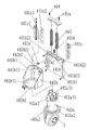
The schematic diagram of Fig. 1 one embodiment of the invention;
Fig. 2 is that one embodiment of the invention drive wheel is connected scheme drawing with first springing;
Fig. 3 is the exploded drawings of Fig. 2;
Fig. 4 is that one embodiment of the invention support wheel is connected scheme drawing with second springing;
Fig. 5 is the structural representation of Fig. 4;
Fig. 6 is the stressed scheme drawing of industrial vehicle when support wheel is two.
Among the figure:
The 1-car body;
The 2-drive wheel;
The 3-support wheel;
4-first springing, 401-slide, 401a-upper plate, 401b-side plate frame, 401b1-side plate; The 401b2-upper cross plate, 401b21-through hole, 401b22-tapped bore, 401b23-center screw, 401c-line slideway; Vee-block in the outer vee-block of 401c1-, the 401c2-, 401c3-guide roller, 401d-stop screw, 401e-the 3rd elastic body, 402-balladeur train; The 402a-Connection Block, 402a1-connects pedestal, 402a2-lower flange, 402a3-mount pad, 402a31-stay bearing plate; 402a32-connects round platform, 402b-support, 402b1-upper flange plate, 402b11-central through hole, 402b12-spring perch; The 402b2-brace panel, 402b21-limiting stopper, 402b3-reinforced rib, 403-first elastic body, 404-screwing;
5-second springing, 501-supports wheel seat, 501a-pedestal, 501b-joint pin, the outer double-screw bolt of 501b1-, 502-terminal pad, 502a – seam, 503-second elastic body, 504-bearing, 505-jam nut.
The specific embodiment
The following stated is merely preferred embodiment of the present invention, is not scope of the present invention is limited.
Embodiment; See accompanying drawing 1,2,3,4,5,6; The present invention relates to a kind of floating installation of industrial vehicle, comprise car body 1, drive wheel 2 and support wheel 3, support wheel 3 is two; Form supported at three points with drive wheel 2, car body 1 is respectively through first springing 4, second springing 5 and said drive wheel 2,3 unsteady connections of support wheel.
First springing 4 comprise slide 401, the balladeur train 402 of captiveing joint of captiveing joint with car body 1 with drive wheel 2 and be arranged on slide 401 and balladeur train 402 between first elastic body 403; First elastic body 403 can adopt spring or elastic caoutchouc; In this embodiment; What adopt is spring, in spring, is with spring bearing, and balladeur train 402 comprises the support 402b that is fixedly coupled a 402a, captives joint with Connection Block 402a with drive wheel 2; Slide 401 comprise upper plate 401a, with upper plate 401a bonded assembly side plate frame 401b, first elastic body, 403 upper ends are connected with upper plate 401a, upper plate 401a is provided with two mounting holes; First elastic body, 403 upper ends are installed in the mounting hole; The lower end is connected with support 402b, and side plate frame 401b is connected with support 402b through two line slideway 401c, and line slideway 401c can adopt gauge member; Outsourcing; Also can adopt the structure of this embodiment, in this embodiment, line slideway 401c comprise outer vee-block 401c1, interior vee-block 401c2 and be arranged on outer vee-block 401c1 and interior vee-block 401c2 between guiding rod 401c3.
Second springing 5 comprises support wheel seat 501, the terminal pad 502 of captiveing joint with said car body 1 of captiveing joint with said support wheel 3 and is arranged on second elastic body 503 between said support wheel seat 501 and the terminal pad 502; Second elastic body can adopt spring or elastic caoutchouc; What this embodiment adopted is the dish spring; The amount of compression of said second springing is 4-10mm, and when the amount of compression of second springing surpassed predetermined value, support wheel was equivalent to be connected with car body with fixed form.
Supporting wheel seat 501 comprises the pedestal 501a of captiveing joint with support wheel 3, is fixed on the joint pin 501b on the said pedestal 501a; The bottom surface of terminal pad 502 is provided with seam 502a, in the said seam 502a bearing 504 is installed, and said bearing 504 is sleeved on the joint pin 501b; Can slide up and down along joint pin 501b; Second elastic body 503 is positioned at said bearing 504 belows, and is sleeved on the said joint pin 501b, simultaneously; Also be set with the slip cap that is positioned at said second elastic body 503 tops on the joint pin 501b; Said joint pin 501b top is provided with the outer double-screw bolt 501b1 that stretches out said bearing 504, is fixed with jam nut 505 on the outer double-screw bolt 501b1, and jam nut 505 can prevent that joint pin 501b breaks away from seam.
In this embodiment; First elastic body 403, line slideway 401c are two, and said two first elastic bodys 403 are between described two line slideway 401c, and are general; First elastic body, line slideway all are symmetrically arranged; Stressing conditions is good like this, and Connection Block 402a comprises connection pedestal 402a1, is fixed on the lower flange 402a2 that connects on the pedestal 402a1, the mount pad 402a3 that is fixed on connection pedestal 402a1 top, and the edge on 402a3 surface is provided with three stay bearing plate 402a31 on the mount pad; Three stay bearing plates are uniformly distributed with setting; Become 120 ° of angles each other, be provided with two screws on the top of stay bearing plate 402a31, the upper surface of mount pad 402a3 upwards extends internally simultaneously to form and connects round platform 402a32; Support 402b comprises the be spirally connected fixing upper flange plate 402b1 with central through hole 402b11, the brace panel 402b2 of captiveing joint with upper flange plate 402b1, two reinforced rib 402b3 with lower flange 402a2, and two reinforced rib 402b3 are connected with upper flange plate with brace panel 402b2 simultaneously.
Be fixed with the spring perch 402b12, the limiting stopper 402b21 that match with first elastic body 403 on the upper flange plate 402b1; Side plate frame 401b comprises side plate 401b1, is fixed on the upper cross plate 401b2 on the side plate 401b1; Outer vee-block 401c1 is fixed on the side plate 401b1; Interior vee-block 401c2 is fixed on brace panel 402b2 both sides; Spring perch can play the effect of support to first elastic body, and first elastic body can be plugged in the endoporus of spring perch, and upper cross plate 401b2 is provided with to be convenient to the through hole 401b21 that first elastic body 403 passes and to be positioned at the center screw 401b23 directly over the limiting stopper 402b21; Through hole 401b21 is provided with opening, and the width of opening is less than the first elastomeric diameter.
Upper plate 401a is connected with upper cross plate 401b2 through two screwings 404; Screwing 404 passes through hole on the upper plate 401a and is spirally connected on the tapped bore 401b22 that is fixed on upper cross plate 401b2; Be bolted with a stop screw 401d on the center screw 401b23, stop screw 401d stretches out the lower end center screw 401b23 and is connected with the 3rd elastic body 401e.The 3rd elastic body can adopt spring, cushion etc.; This 3rd elastic body does not act on when zero load; And under vehicle heavy duty situation, a higher positive pressure can be provided outside first elastic body; So with respect to first elastic body and second elastic body, the 3rd springing amount of compression is less, the needed power of its elastic deformation is bigger.The floating space that first springing makes progress can be regulated, and the amount of floating that finally makes progress is less than the amount of compression of second springing.
See accompanying drawing 6; All-electric transport trolley comprises two front-wheels and two support wheels, comes comparative analysis with concrete test figures: wherein; Drive wheel bears a heavy burden and representes with FO, and the near front wheel bears a heavy burden, off front wheel bears a heavy burden, left support wheel bears a heavy burden and right support wheel bears a heavy burden representes with F1, F2, F3, F4 respectively;
Be connected when experimental model adopts drive wheel to float with car body, and left and right sides support wheel is connected with rigidity of vehicle body, when unloaded, gross weight 787 Kg find through test, at this moment:
F1=100?Kg,?F2=90Kg?,?F3=72?Kg?,?F4=75Kg?,F0=450?Kg;
When its load-carrying 2400kg, be heavy duty at this moment, about 3200 Kg of gross weight;
F1=1090Kg?,?F2=1060Kg,?F3=280?Kg?,F4=320Kg?,F0=453?Kg;
This shows: when load-carrying was 2400kg, the power on the drive wheel only increased: 453Kg-450Kg=3kg; Do not considering other influence factors; Coulomb (Coublomb) law of friction classical formulas F=μ * N that knows according to technical personnel (be friction force equal friction coefficient multiply by positive pressure); The propulsive effort that drive wheel can provide becomes the forward proportionate relationship with the positive pressure over the ground of drive wheel; So drive wheel floats, when support wheel is fixed on load-carrying, very likely make drive wheel produce skidding.
When adopting drive wheel all to float with car body with support wheel, experimental model is connected, and adjustment drive wheel caging bolt, when its load-carrying 2400kg:
F1=1100?Kg,?F2=1060Kg,?F3=235?Kg,?F4=242Kg,F0=555Kg;
Do not consider other influence factors; According to we knew coulomb (Coublomb) law of friction classical formulas F=μ * N (be friction force equal friction coefficient multiply by positive pressure), the propulsive effort that drive wheel can provide becomes the forward proportionate relationship with the positive pressure over the ground of drive wheel.In this sense, we find that drive wheel positive pressure over the ground differs 105Kg under sky, heavily loaded situation.Because positive pressure and load-carrying have 6-8 proportionate relationship doubly over the ground, after implementing to improve, under identical body construction; Can increase the load-carrying of 630-840Kg and non-slip, in other words, the car that possibly skid originally; After adopting structure of the present invention, can normally move and no longer skid.
More than explanation only is to explanation of the present invention; Make enforcement this programme that those of ordinary skills can be complete; But be not limitation of the present invention; Those skilled in the art can make the modification that does not have creative contribution to present embodiment as required after reading this specification sheets, these all are not creative modifications.But as long as in claim scope of the present invention, all receive the protection of patent law.