CN102822552A - System and methods for optimizing efficiency of a hydraulically actuated system - Google Patents
System and methods for optimizing efficiency of a hydraulically actuated system Download PDFInfo
- Publication number
- CN102822552A CN102822552A CN2010800634045A CN201080063404A CN102822552A CN 102822552 A CN102822552 A CN 102822552A CN 2010800634045 A CN2010800634045 A CN 2010800634045A CN 201080063404 A CN201080063404 A CN 201080063404A CN 102822552 A CN102822552 A CN 102822552A
- Authority
- CN
- China
- Prior art keywords
- hydraulic
- piston
- fluid
- actuator
- chamber
- Prior art date
- Legal status (The legal status is an assumption and is not a legal conclusion. Google has not performed a legal analysis and makes no representation as to the accuracy of the status listed.)
- Pending
Links
Images


Classifications
-
- F—MECHANICAL ENGINEERING; LIGHTING; HEATING; WEAPONS; BLASTING
- F02—COMBUSTION ENGINES; HOT-GAS OR COMBUSTION-PRODUCT ENGINE PLANTS
- F02C—GAS-TURBINE PLANTS; AIR INTAKES FOR JET-PROPULSION PLANTS; CONTROLLING FUEL SUPPLY IN AIR-BREATHING JET-PROPULSION PLANTS
- F02C6/00—Plural gas-turbine plants; Combinations of gas-turbine plants with other apparatus; Adaptations of gas- turbine plants for special use
- F02C6/14—Gas-turbine plants having means for storing energy, e.g. for meeting peak loads
- F02C6/16—Gas-turbine plants having means for storing energy, e.g. for meeting peak loads for storing compressed air
-
- Y—GENERAL TAGGING OF NEW TECHNOLOGICAL DEVELOPMENTS; GENERAL TAGGING OF CROSS-SECTIONAL TECHNOLOGIES SPANNING OVER SEVERAL SECTIONS OF THE IPC; TECHNICAL SUBJECTS COVERED BY FORMER USPC CROSS-REFERENCE ART COLLECTIONS [XRACs] AND DIGESTS
- Y02—TECHNOLOGIES OR APPLICATIONS FOR MITIGATION OR ADAPTATION AGAINST CLIMATE CHANGE
- Y02E—REDUCTION OF GREENHOUSE GAS [GHG] EMISSIONS, RELATED TO ENERGY GENERATION, TRANSMISSION OR DISTRIBUTION
- Y02E60/00—Enabling technologies; Technologies with a potential or indirect contribution to GHG emissions mitigation
- Y02E60/16—Mechanical energy storage, e.g. flywheels or pressurised fluids
-
- Y—GENERAL TAGGING OF NEW TECHNOLOGICAL DEVELOPMENTS; GENERAL TAGGING OF CROSS-SECTIONAL TECHNOLOGIES SPANNING OVER SEVERAL SECTIONS OF THE IPC; TECHNICAL SUBJECTS COVERED BY FORMER USPC CROSS-REFERENCE ART COLLECTIONS [XRACs] AND DIGESTS
- Y02—TECHNOLOGIES OR APPLICATIONS FOR MITIGATION OR ADAPTATION AGAINST CLIMATE CHANGE
- Y02T—CLIMATE CHANGE MITIGATION TECHNOLOGIES RELATED TO TRANSPORTATION
- Y02T50/00—Aeronautics or air transport
- Y02T50/60—Efficient propulsion technologies, e.g. for aircraft
Abstract
Systems and methods for efficiently operating a hydraulically actuated device/system are described herein. For example, systems and methods for efficiently operating a gas compression and expansion energy storage system are disclosed herein. Systems and methods are provided for controlling and operating the hydraulic actuators used within a hydraulically actuated device/system, such as, for example, a gas compression and/or expansion energy system, within a desired efficiency range of the hydraulic pump(s)/motor(s) used to supply or receive pressurized hydraulic fluid to or from the hydraulic actuators. In such a system, a variety of different operating regimes can be used depending on the desired output gas pressure and the desired stored pressure of the compressed gas. Hydraulic cylinders used to drive working pistons within the system can be selectively actuated to achieve varying force outputs to incrementally increase the gas pressure within the system for a given cycle.
Description
Cross reference
The application requires in the preference and the interests of the U.S. Provisional Patent Application sequence number 61/290107 of " optimizing the system and method for hydraulic actuation system efficient " by name of submission on December 24th, 2009, and the disclosure of this application is used as reference and all introduces among this paper.
Technical field
Present invention relates in general to optimize the system and method for hydraulic actuation system energy efficiency, for example be used to adopt the system and method for optimizing pressurized gas energy-storage system efficient to come stored energy.
Background technique
Usually, the scale of power plant has been set to and has adapted to the peak value energy requirement.In addition, being provided with of power plant's scale must be considered its peak output output, minimum power output and the middle power output area that most effectively fuel is changed into electricity.Power plant is restricted aspect also how can starting rapidly and close, and closes usually power plant also also infeasible fully.Power export-restriction and startup and close restriction and joined together to limit the ability that power plant optimally satisfies the power demand of fluctuation.These restrictions can cause greenhouse gas emission increase, overall fuel consumption to increase and/or running cost maybe higher and other defective.Enlarging has the power plant of energy-storage system to produce to be used for energy is stored for subsequent use capacity, and this makes that power plant can be according to making the minimum mode of above-mentioned defective satisfy the user's request of fluctuation.
Energy-storage system can improve integrated operation cost, reliability and/or the effulent scale of power plant.But there is shortcoming in existing energy storage technologies.For example, storage battery, flywheel, capacitor and fuel cell can provide fast the response time and help to compensate interim outage, but its energy storage capacity is limited, and implementation cost is also high.Install other more large-scale capacity system for example pumped storage need the Special geography landform, this is not can find in all places.
The intermittent type generating field for example capacity of some wind energy turbine set has surpassed transmission line capability.But do not have suitable energy-storage system, this intermittent type generating field can not be operated with full capacity.The claimant recognizes, the intermittent type power station can be when the power station can be with the speed power generation higher than speed power transmission obtains advantage the energy-storage system of stored energy from being used for.When the electric weight of intermittent type generating field generation was lower than the electric transmission line capacity, the energy of being stored just can discharge through electric transmission line.
Its power consumption of power consumption place---such as building, small towns, city, commercial facility, military installations---can periodically surpass transmission line capability.Do not have suitable energy-storage system, this power consumption user can not be with preferred levels operation.The claimant recognizes; The limited power consumption place of transmitting electricity can obtain advantage from energy-storage system; So the specification of this energy-storage system can be configured to make stored energy when but the power consumption field is lower than the speed consumed energy of speed power transmission, and those just can be stored by the used up energy that is transmitted of horse back.When user's power consumption was higher than the transmission line capacity, the energy of being stored can discharge through transmission line.
Compressed-air energy-storage system (CAES) is another kind of only for the system that is used for the known type of pressurized air stored in form energy.The CAES system can be used for when electric demand is low (usually at night) with compressed-air actuated stored in form energy, and (usually in the daytime) releases energy when electric demand is higher.Thereby comprising usually, this system operates air is compressed the compressor of stored energy with constant speed.Typically, utilizing the turbo machine that separates with compressor that pressurized air is expanded generates electricity.But the pressurized air that turbo machine requires to be provided usually has relative constant compression force, for example about 35 barometric pressure.Additionally or alternatively, pressure is higher than 35 atmospheric air need be by throttling before in turbo machine, expanding, and the loss that is caused has reduced system effectiveness and/or reduced the energy density that energy storing structure held.In addition; In order to increase the electric energy that each unit of air of expanding through turbo machine is produced; Pressurized air in the system was preheated to higher temperature (for example 1000 ℃) through combustion of fossil fuels usually before will expanding; This had both increased the system capacity cost, also produced and the relevant effulent of energy storage.
Become known for that energy is had the multistage (multi-stage) compressor with the CAES type system of pressurized air stores, it can be included in the interstage cooler of cooling air between each compression stage and/or the aftercooler of cooling air after compression.But in this system, air still produced higher temperature during each compression stage before cooling, and this can cause system effectiveness to reduce.Therefore, need let CAES type system have higher efficient.
The CAES system can utilize the hydraulic driving system of being made up of hydraulic unit (for example oil hydraulic pump) to implement.Therefore; Compressed-air energy-storage system or be used for is compressed and/or other system of expanding gas realizes the system and method for high efficiency output, it comprises the pressure that can regulate or change the hydraulic fluid in the employed oil hydraulic pump when this system of operation and/or the controller and the operator scheme of flow.
Summary of the invention
This paper has described the system and method that is used for the hydraulic actuator device/system of operating effectively.For example, this paper has disclosed the system and method that is used for operating gas compression effectively and expansion energy-storage system.This paper provides the hydraulic pump/motor that is used for using in hydraulic actuator device/system's (for example gas compression and/or expansion energy-storage system) in the maximal efficiency scope at pump during the whole circulation of system, to control and operated system and method.In this system, can adopt various operating conditions with expectation storage pressure according to the desired output gas pressure of pressurized gas.Being used for the oil hydraulic cylinder of the working piston in the drive system can optionally be activated and/or can be activated, so that realize the active force output that changes, thereby little by little increases intrasystem gas pressure to given circulation.
Description of drawings
Fig. 1 is the principle schematic representation according to an embodiment's air compression and expansion energy system.
Fig. 2 A is the principle schematic representation according to an embodiment's air compression and expansion energy system, demonstrates the energy stream during compression cycle.
Fig. 2 B is the principle schematic representation according to an embodiment's air compression and expansion energy system, demonstrates the energy stream during expansion cycle.
Fig. 3 demonstrates an embodiment's of air compression and expansion system the single stage.
Fig. 4 demonstrates the embodiment that can be used in the divider in the pressurized container.
Fig. 5 A is another embodiment's of air compression and expansion system the principle schematic representation of a part.
Fig. 5 B is the principle schematic representation of a part of air compression and the expansion system of Fig. 5 A, demonstrates SC system controller and oil hydraulic pump.
Fig. 6 A and Fig. 6 B are respectively the principle schematic representation of a part of actuator of air compression and the expansion system of Fig. 5.
Fig. 6 C is the side view of a part of actuator of the system of Fig. 5.
Fig. 6 D is the sectional view that obtains along the 6D-6D line among Fig. 6 C.
Fig. 6 E is the sectional view that obtains along the 6E-6E line among Fig. 6 C.
Fig. 6 F is the sectional view that obtains along the 6F-6F line among Fig. 6 C.
Fig. 7-Figure 14 demonstrates according to an air compression process embodiment, that carry out with the system of Fig. 5.
Figure 15-Figure 22 demonstrates according to an air expansion process embodiment, that carry out with the system of Fig. 5.
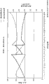
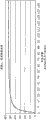
Figure 23-Figure 50 is respectively example chart, demonstrates and compression and the operation of expansion system and various parameters that output is associated according to each embodiment.
Figure 51 A is the principle schematic representation according to an embodiment's actuator.
Figure 51 B and Figure 51 C comprise a plurality of principle schematic representation of the actuator of Figure 51 A respectively, demonstrate the different gears (gear) of actuator.
Figure 51 D is a form, demonstrates the various parameters relevant with being implemented in a plurality of different gears shown in Figure 51 B and Figure 51 C.
Figure 52 A is the principle schematic representation according to another embodiment's actuator.
Figure 52 B and Figure 52 C comprise a plurality of principle schematic representation of the actuator of Figure 52 A respectively, demonstrate the different gears of actuator.
Figure 53 is the principle schematic representation according to another embodiment's actuator.
Figure 54 A is for the principle schematic representation according to another embodiment's actuator shown in first state.
Figure 54 B be shown in one second state, according to the principle schematic representation of another embodiment's actuator.
Figure 55 is the principle schematic representation according to another embodiment's actuator.
Figure 56 is the principle schematic representation according to another embodiment's actuator.
Embodiment
This paper has disclosed the system and method that is used for operating gas compression effectively and/or expansion system.This gas compression and/or expansion system can adopt one or more hydraulic pump/motors; So that make intrasystem gas and liquid motion (or by these gases and liquid driven), this paper has also described and has been used for during the operation cycle of system or stroke, making hydraulic pump/motor in its effective condition continuously or basically operated system and method continuously.Oil hydraulic pump can have effective operating range, and these operating ranges can be for example according to flow and pressure and the variation of other parameter.This paper the operation hydraulic pump/motor is provided so that its in the whole stroke of gas compression and/or expansion system or circulation with the system and method for optimum efficiency effect.
Such as this paper description ground; In certain embodiments; Hydraulic pump/motor can be used for the working piston (or driven by it) in propellant compression and/or the expansion system; Wherein working piston can act on the gas (or by this gas effect) that is accommodated in the work chamber, so that directly make gas compression or expansion, perhaps makes gas compression or expansion through the liquid that is arranged between the gas in working piston and the work chamber indirectly.The hydraulic pressure load that is applied on the working piston can change in the given cycle period of system.For example; Apply hydraulic fluid pressure through the different hydraulic pistons in hydraulic pump/motor and/or the different surfaces of piston; The ratio of the clean worksheet area of hydraulic actuator and the worksheet area that acts on the gas in the work chamber of working piston can change, so the ratio of the gas pressure in hydraulic fluid pressure and the work chamber can change during the given circulation of system or stroke.In addition, the quantity of the piston area rate of change in the quantity of working piston/work chamber and oil hydraulic cylinder and the given circulation can change.As used herein is the same, and term " piston " is not limited to cross section for circular piston, can also comprise that cross section is the piston of triangle, rectangle or other polygonal shape.
Can comprise one or more compressions and/or expansion stage like gas compression described herein and/or expansion system.For example, system can comprise single phase compression/expansion device, two stage compression/expansion gear, three stage compression/expansion gear etc.As described herein, as will describing in detail with reference to specific embodiment below, system can also comprise " gear switch (the gear shift) " or " gear change (gear change) " in the given stage.As used herein is the same; Term " gear switch " or " gear change " are used for the variation of ratio of gas pressure in hydraulic fluid pressure and the work chamber in the hydraulic actuator chamber of describing activity, activated (or actuate hydraulic) by hydraulic actuator, and described ratio is actually that the pressing surfaces of working piston is long-pending and the ratio of the net area (net area) that the pressing surfaces of the hydraulic piston that activates working piston is long-pending.As used herein is the same; Term " gear " refers to a kind of like this state; Wherein hydraulic actuator preset time have in the section specific piston area ratio (for example, the clean work area of hydraulic actuator and working piston act in the work chamber gas or by the ratio of the worksheet area of this gas effect).
In certain embodiments; As hydraulic actuator described herein can be used to drive in water pump/motor for example working piston or by this piston actuated, so that water (or other liquid) moved in and out for the work chamber that makes gas (for example air) compression that is accommodated in the work chamber and/or the pressurized container that expands.Such as this paper description ground, actuator can also comprise multiple " gear change " (as described above) during the circulation of actuator or stroke.In certain embodiments, can be used for the working piston of drive arrangement in compression and/or expansion gear perhaps by this piston actuated like actuator described herein.For example, in certain embodiments, can drive working piston and be compressed in the one or more fluids in the work chamber.As used herein is the same, and " fluid " can refer to liquid, gas, steam, suspension, aerosol or its combination in any.Though actuator specific embodiment described herein is for driving water pump/motor and/or compression and/or expansion gear; Perhaps by water pump/motor and/or compression and/or expansion gear driving; But it should be understood that; Each embodiment of actuator and structure can be used for driving water pump, compression and expansion gear, compression set, expansion gear, any other working piston that utilizes makes device and/or any can power being applied above that maybe of fluid motion can be from the working piston in the device of received power wherein, perhaps by this piston actuated.
In certain embodiments, apparatus and method described herein can be configured to just as compressor.For example, in certain embodiments, compressor set described herein can be as needing the compressor in the industrial applications of gas compression at natural gas line, natural gas storage compressor and any other.In another embodiment, compressor set described herein can be used for compression arbon dioxide.For example, carbon dioxide can be compressed in the process that is used for strengthening petroleum recovery.In another embodiment, compressor set described herein can be used for pressurized air.For example, pressurized air can be used in the various application occasions, and these applications can comprise clean applications occasion, power applications, ventilatory applications occasion, air separation application, cooling application or the like.
In certain embodiments, device described herein and system can constitute just as expansion gear.For example, can be used for generating like expansion gear described herein.In certain embodiments, can be used in rock gas transmission and the distribution system like expansion gear described herein.For example, in the cross-shaped portion office of high pressure (for example 500psi) transmission system and low pressure (for example 50psi) distribution system, energy can obtain discharging and make pressure progressively be reduced to low pressure from high pressure.Can utilize this pressure drop to generate electricity like expansion gear described herein.
In certain embodiments, can be used in the air-separating plant like compression described herein and/or expansion gear.In an exemplary application occasion, in deaerator, compression and/or expansion gear can be used in the gas liquefaction process.For example, can air compression be liquefied up to it, and the various components of air are separated according to its different boiling point.In another exemplary application occasion, compression and/or expansion gear can be used in is built together in the deaerator of steel works, and wherein, the oxygen that separates with other component of air is added in the blast furnace to improve FT.
Compression and/or expansion system can have various structure, and can comprise one or more actuators that are used for making the air compression/expansion in the compression/expansion device.In certain embodiments; Actuator can comprise one or more pump/motor system (such as one or more hydraulic pump/motors for example); It can be used for making intrasystem one or more fluid between each water pump/motor and pressurized container, to move, perhaps by this fluid drives.The U.S. Provisional Patent Application No.61/216942 that submits on May 22nd, 2009 and submit to respectively on May 21st, 2010, it is by name that " the U.S. Patent application No.12/785086,12/785093 and 12/785100 of compressor and/or decompressor device (this paper is referred to as " compressor and/or the application of decompressor device ") has described the various energy compressions and/or the expansion system that wherein can adopt system and method described herein, and these documents are used as with reference to all introducing among this paper.
Technological as a setting, Fig. 1 is the embodiment's of energy-storage system 100 a principle schematic representation, the energy release of wherein having adopted compressor/decompressor device to come energy storage and will having stored before.As shown in Figure 1, comprise that the wind energy turbine set 102 of a plurality of wind turbines 104 can be used for gathering in the crops wind energy and it is transformed into electric energy to send motor/generator 110 to.It being understood that system 100 can with except that wind energy turbine set, for example use with the electricity of electrical network (electric power grid) or sun-generated electric power source.Motor/generator 110 will be transformed into mechanical output from the input electric power in wind turbine or other source.Can utilize mechanical output to drive hydraulic pump/motor 111 then.Hydraulic pump/motor is transformed into the hydraulic power that can be used for driving with the hydraulic actuator 112 that compressor/decompressor device 120 is connected with the mechanical output of input.
Energy can be with the pressurized gas stored in form in system 100, and this pressurized gas can expand the energy with storage before obtaining in the later time section.In order to store the energy that is produced by wind energy turbine set 102, hydraulic actuator 112 can change the volume (for example through making piston in cylinder, move) of work chamber and/or liquid is introduced in the work chamber to reduce to can be used in the work chamber volume of gas.The reducing of volume makes gas be compressed.During this process, can remove heat from gas.During this process, gas is transmitted to the downstream stages of compressor/decompressor device 120, and finally sends compressed gas storage structure 122 (this paper also is referred to as " gas tank ") to higher pressure.Subsequently, for example when electrical network is higher relatively to the demand of electric energy, perhaps when electricity price is higher, can from storage organization 122, emit pressurized gas, and gas expanded through compressor/decompressor device 120.Pressurized gas expands and drives hydraulic actuator 112, hydraulic actuator then drive hydraulic pump/motor 111 producing mechanical output with hydraulic power, this mechanical output again drive motor/generator 110 to produce the electric power that is used to send to electrical network 124.Be in the heat under the relative low temperature (for example between about 10 ℃ and about 90 ℃) can for the gas interpolation between the phase of expansion, thus the energy that the per unit gaseous mass is produced during the raising inflation process.Can be in the heat under the temperature relatively-high temperature degree (for example about more than 90 ℃) in interpolation between the phase of expansion, thereby improve the energy that per unit mass produced during inflation process.
Fig. 2 A is the principle schematic representation through the energy stream of the multiphase system 200 of system 100 in an illustrative operational states, that be similar to Fig. 1.Gas (being air in this example) just is being compressed so that store.As above describe ground, for example the electric power from wind energy turbine set is used to drive motor/generator 210 to produce mechanical output, and this mechanical output transfers to drive hydraulic pump/motor 211 to produce hydraulic power, and this hydraulic power is drive actuator 212 again.What actuator 212 can reduce work chamber can be used to hold volume of air, thereby makes air compression.
Shown in Fig. 2 A, multiple stage compressor/decompressor device 220 can be at the phase I of compressor/decompressor device 220 reception environment air.In certain embodiments, alternatively, ambient air can be handled in precompression machine 215 before the phase I that is supplied to compressor/decompressor device 220.Heat energy can be removed via the liquid in the work chamber of multiple stage compressor/decompressor device 220 between compression period, so that the air is by compression remained under the relative stationary temperature.Heat energy can for example pass to for example radiator through heat exchanger from liquid and compressor/decompressor device 220.According to an embodiment, before the pressure with about 3000psi sent storage organization 222 to, air for example located to realize respectively the approximately pressure of 150psi, 1000psi and 3000psi in first, second and each stage in the phase III.Before being supplied to compressor/decompressor device 220 and initially being compressed and cooling off, it is constant relatively that the temperature of air keeps, and for example remains under about 5 ℃, 10 ℃, 20 ℃, 30 ℃ or other desired temperature, gives storage organization 222 up to discharging.Be in higher (or lower) temperature following time when storage organization 222 is natural, the air that is stored in the storage organization 220 can be heated (or cooling) naturally through conductivity and convective heat exchange.For example, in some cases, storage organization can be underground structure, for example is structured in the salt hole in the salt dome.It being understood that Fig. 2 A demonstrates a kind of serviceability of an embodiment of system, also have other serviceability, and other embodiment that can taking into account system.
Fig. 2 B is a schematic representation, shows the energy of emitting when being used for produce power the system 200 through Fig. 2 A under a serviceability from storage when air and flows.In an illustrative operational states; Air in the storage organization 222 can be in the pressure of about 3000psi, and can through compressor/decompressor device the 3rd, second and the phase I for example expand into the approximately pressure of 1000psi, 150psi and 0psi respectively.Can be before expanding and/or between the phase of expansion respectively the 3rd, second and the phase I in each stage locate to add heat to air; So that during the whole inflation process air temperature is being remained under the temperature of substantial constant, for example remain under about 35 ℃ or other temperature.It being understood that air can receive a large amount of relatively air restriction of expanding in the relatively little volume at pressurized container and contacting with sizable heating surface in the total temperature change between the phase of expansion.It being understood that preferably and to make air temperature obviously be increased to and for example to be higher than 35 ℃ temperature so to air heating.Compressor/decompressor device 220 produces mechanical output, and this mechanical output is converted to hydraulic power by hydraulic actuator 212 and imposes on hydraulic pump/motor 211, and hydraulic pump/motor converts hydraulic power to mechanical output again.This mechanical output is applied in to motor/generator 210, and motor/generator is transformed into electric power with mechanical output again.It being understood that and alternatively to adopt the actuator except hydraulic actuator.As another generating source, when the air that expands left the phase I of compressor/decompressor device 220, air can be supplied to air turbine 217 alternatively, and air turbine converts air to mechanical output.Mechanical output can be applied in to motor/generator 219, converts mechanical output to electric power.
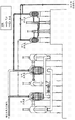
Fig. 3 demonstrates the part of compressed-air energy-storage system 300, and it comprises compressor/decompressor device 320 and actuator 312.Compressor/decompressor device 320 illustrates the single stage of compressed-air energy-storage system.Compressor/decompressor device 320 comprises first pressurized container 324 and second pressurized container 326.First and second pressurized containers 324,326 respectively are connected with actuator 312 fluids respectively with 330 through pipeline or housing 328.Actuator 312 can comprise the water pump with hydraulic drive type piston 332.Piston 332 is arranged in housing or the reservoir 340; And can enough one or more oil hydraulic pumps (not shown among Fig. 3) drive with towards with pipeline 328 motions away from first pressurized container 324; Thereby alternately reduce to increase again the internal air volume (equally still on the contrary, increasing the volume of air that reduces second pressurized container 326 again) of first pressurized container 324.In first and second pressurized containers 324,326 each is partially filled at least to have liquid (for example water); Liquid is driven by actuator 312; So that operation the time is alternately compressed and driven the gas volume from each pressurized container in first and second pressurized containers 324,326 in compact model, receive the compressed air-driven in any pressurized container that is received in first and second pressurized containers 324,326 when perhaps in expansion mechanism, operating.
Each pressurized container 324,326 can be set for to limit and is used for compressing and/or the work chamber of expanding gas.The volume of work chamber is limited the volume of pressurized container.Work chamber can hold gas with a part of volume, and comes receiving fluids with a part---and the total measurement (volume) that part of volume that holds gas equals work chamber deducts that part of volume of receiving fluids.The operation water pump is driven liquid the pressurized container from pumping cylinder, makes that part of volume that can hold gas of work chamber reduce, thereby the gas that is contained in that part of is compressed (for example during compression cycle).Similarly, the operation water pump sends liquid to water pump from pressurized container, makes that part of volume that can hold gas of work chamber increase, thereby allows gas to expand.Optional is, can work chamber is arranged to limit through any pipeline or other volume pressurized container and water pump and that the pressurized container fluid is communicated with that part of (promptly on a side of working piston) and is connected pressurized container and water pump.The work chamber that so limits has variable volume, and this volume can change through the motion of working piston.Part in the variable-volume can be occupied by liquid (for example water), and remainder can be occupied by gas (for example air).The pressure that is contained in the gas in the work chamber is substantially equal to be contained in the pressure of any liquid in the work chamber, and equals to act on the side of working piston or the pressure on the face.
Compressor/decompressor device 320 can also comprise fin, divider and/or the pallet 334 that can be positioned at first and second pressurized containers, 324,326 inside.Divider 334 can increase the gross area that directly or indirectly contacts with air in the pressurized container, thereby can improve heat transmission.Divider 334 can for the air by compression with expanded in air increase is provided heat transfer area (through air/liquid interface area; Perhaps through air/divider interface), global shape and the size and the external structure of pressurized container optimized in permission simultaneously to other Consideration (for example pressure limit value and/or transportation clearance limiting value).
In this embodiment, divider 334 is arranged in first and second pressurized containers 324 and 326 with the duplexer structure.Each divider 334 can be configured and be used for keeping air pocket.In one exemplary embodiment, each divider 334 can comprise upper wall, to sidewall that extends below and unlimited bottom, and wherein, said sidewall is consistent with the pressurized container inwall in shape, and dimensionally with pressurized container inwall basically identical.When pressurized container was operational orientation, the bottom faces of opening wide of each divider 334 was facing to direction common, basically down.Should be understood that; Though these accompanying drawings demonstrate size shape and pressurized container 324,326 inner consistent and dividers that be shaped similarly each other substantially; But also can consider and conceive other structure; It is inner and/or the embodiment that differs from one another of the shape and size of cut piece, perhaps other structure to comprise that divider is significantly less than pressurized container on width.Can adopt various other shapes and the structure of divider, such as for example passing through with reference to shown in compressor of introducing and/or the application of decompressor device and the described divider at U.S. Provisional Application No.61/216942 and preceding text.Fig. 4 demonstrates another alternative of the divider that can adopt.It being understood that divider can comprise fin structure (array of pin or bar, and other porous structure), this has improved the area that can be used for heat exchange, and has improved the degree of approach of air and divider, and can conceive the divider that does not keep air pocket.In certain embodiments, divider can be for supporting the structure of moisture film.In certain embodiments, the space between the divider is not empty, can between cut piece, have intermediate structure, for example the array of pin or bar, impaltatle structure, porous structure etc.
As shown in Figure 3, manifold 336 can extend through the duplexer of divider 334 in central authorities, and each divider 334 is connected with inlet/outlet 338 fluids of pressurized container 324,326.In other embodiments, manifold can comprise a plurality of pipes and/or can perhaps be positioned in other position circumferentially around the duplexer location of divider.Air can get into and/or leave pressurized container 324,326 through port 338, and can be provided for air pocket that each divider 334 is associated between carry out the pipeline that fluid is communicated with.Other embodiment for example wherein divider do not keep among the embodiment of air pocket, can not comprise manifold.
Ground is as above described, can be from pressurized container, being passed out heat by liquid (for example water) air compressed, and/or the air that heat transferred is expanded by liquid (for example water) in pressurized container.Air/liquid or air/divider interface (for example part provide) by above-mentioned divider can be in pressurized container compression and/or inflation process during motion and/or change shape.This motion and/or alteration of form can provide a kind of like this compressor/decompressor device, and the heat transfer surface that this compressor/the decompressor device is had can adapt to the changes shape that between the compression and/or the phase of expansion, transmits the pressurized container internal area of heat.In certain embodiments, (being the Zero clearance volume) almost removed or removed fully to that part of volume of air of staying after liquid can let and compress in the pressurized container.
Liquid (for example water) is compared with gas (for example air) can have higher relatively thermal capacitance, rises thereby the thermal energy transfer from gas to liquid has obviously reduced the temperature of gas, causes just that but the appropriateness of fluid temperature increases.This makes it possible to alleviate the influence of obvious temperature variation to system.Between gas and the liquid or the heat that transmits between a plurality of parts at container self can leave or arrive pressurized container through the one or more heat exchangers motion that contacts with a plurality of parts of liquid or container.As more specifying below, a kind of heat exchanger that for this reason can adopt is a heat pipe.
Therefore; Liquid in the pressurized container can be used to transmit the heat (or with heat transferred expanding gas) of pressurized gas, and the liquid of describing can also with the heat exchanger set cooperation in order to heat transferred external environment condition (perhaps from external environment condition, absorbing heat).For example, as shown in Figure 3, heat exchanger comprises the circular array of heat pipe 342, and these heat pipes extend through the wall of pressurized container 324 and 326, and can the two contacts with liquid and external environment condition in the container.Heat pipe 342 only is to be used to transmit the exemplary embodiment that heat is given pressurized container liquid or transmitted this heat exchanger of pressurized container liquid heat.It should be understood that alternatively, can adopt the heat exchanger and other heat pipe structure of other type.For example, can adopt (alternatively or extraly) other heat management device, for example the shape of fin, pin, generation convection current and/or produce the shape etc. of eddy current.
The embodiment of Fig. 3 is for being used in an interior pressurized container of gas compression and storage system and an embodiment of actuator arrangement.It should be understood that and also can envision other possible layout.For example; Though actuator is shown as and comprises that vertical orientated single two-way ram, the included housing of other embodiment have and comprise the horizontal alignment piston and/or comprise a plurality of the operation so that the actuator of the hydraulic piston that fluid moves in pressurized container parallelly connectedly.According to some embodiments, actuator can not have piston together, and the ground that replaces, actuator comprise the pump that lets fluid move in and out pressurized container.According to some embodiments, can be extraly or alternatively parallel connection use a plurality of pumps and/or piston to move in and out pressurized container by fluid.Also have, according to other embodiment, because the system implementation example is not limited at shown in these accompanying drawings those, for example the actuator of hydraulic piston can be connected with the motor/generator direct mechanical of system.
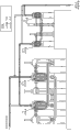
Fig. 5 A-Figure 18 demonstrates the example of two stage energy compressions and expansion system 400.Fig. 5 A is the principle schematic representation of the part of system 400.Phase I comprises a pair of pressurized container 424,426 that the mode that is communicated with fluid is connected with actuator 412.For example, can adopt all kinds pipeline or housing (shown in Fig. 5 A) that each parts of actuator 412 are connected with the pressurized container fluid.Pressurized container 424,426 such as above to the description of front embodiment institute each can comprise divider or pallet (not shown among Fig. 5 A).Actuator 412 comprise such as hereinafter description ground by the water pump of hydraulic actuator or Driven by Hydraulic Cylinder.Shown in Fig. 5 A, actuator 412 comprises water pump 444A, 444B and 446.In this embodiment, water pump 444A and 444B constitute with two parts, so that reduce the height of pumping installations, and water pump 444A is used as single pump simultaneously with 444B in this embodiment.Each water pump among water pump 444A, the 444B and 446 comprises water piston or the working piston that hydraulically drives with pair of hydraulic cylinders.Water pump 444A is connected with 454 with oil hydraulic cylinder 452, and by these two Driven by Hydraulic Cylinder; Water pump 444B is connected with 458 with oil hydraulic cylinder 456, and by these two Driven by Hydraulic Cylinder; And water pump 446 is connected with 450 with oil hydraulic cylinder 448, and by these two Driven by Hydraulic Cylinder.Common driveshaft connects its corresponding oil hydraulic cylinder of water piston.The oil hydraulic cylinder of phase I can both hard to bear Fig. 5 B shown in 414 controls of the first efficient hydraulic pump.Can adopt the hydraulic pump/motor such as the Artemis Digital Displacement oil hydraulic pump of for example Artemis Intelligent Power Ltd. manufacturing.Other example of the oil hydraulic pump that can use is able to describe in the United States Patent(USP) No. 5259738 of the United States Patent(USP) No. that is called " digital fluid pump (Digital Fluid Pump) " 7001158 and " fluid machine for doing work (Fluid-Working Machine) " by name, and the full content of these documents is used as with reference among introducing this paper.
Shown in Fig. 5 B, can adopt SC system controller or hydraulic controller 416 to operate and control hydraulic pump/motor 414.Hydraulic pump/motor 414 can be connected to each end of the oil hydraulic cylinder that is associated with each water pump (or work actuator) of system.Be connected with valve between each end of oil hydraulic cylinder (being each hydraulic chamber) and the oil hydraulic pump; Valve for example can optionally open and close under hydraulic controller 416 controls; So that the output of oil hydraulic pump 414 and each hydraulic chamber of each oil hydraulic cylinder are connected or isolate in fluid ground respectively; Thereby optionally activate specific oil hydraulic cylinder; And more specifically be actuated at the hydraulic piston in the specific oil hydraulic cylinder particular side (for example blind side and/or bar side, as below the institute in greater detail).Each valve 418 represented by in Fig. 5 B.
Shown in Fig. 5 A, the second stage of system 400 comprise with a pair of pressurized container 462 and 464 that comprises that mode that water pump 466 and 468 actuator 413 fluids are communicated with is connected.Identical with the structure of phase I; In the pressurized container 462 and 464 each can comprise divider; And also shown in Fig. 5 A, each in the water pump 466 and 468 comprise by pair of hydraulic cylinders hydraulically drive the water piston of (perhaps in expansion mechanism, driving this) to oil hydraulic cylinder.Water pump 466 is connected with 472 with oil hydraulic cylinder 470 and is driven by it, and water pump 468 is connected with 476 with oil hydraulic cylinder 474, and by these two Driven by Hydraulic Cylinder.The oil hydraulic cylinder of second stage can be according to utilizing same hydraulic controller 416 or utilize the second hydraulic controller (not shown) to drive or drive this second efficient hydraulic pump/motor through the second efficient hydraulic pump/motor (not shown) with similar mode of phase I.It being understood that the second stage oil hydraulic cylinder can perhaps drive these hydraulic pump/motors by the hydraulic pump/motor driving of various structures, and system 400 for example can have one, two, three, four or more a plurality of hydraulic pump/motor.
In first and second pressurized containers 424 and 426 of phase I each is connected with 464 fluids with the pressurized container 462 of second stage through pipeline, and this pipeline can comprise that one or more valves (not shown in Fig. 5 A) are communicated with the fluid that optionally opens and closes between the volume of relevant pressure container.Each all can also comprise the valve (not shown) first pressurized container 424 of phase I and second pressurized container 426, and this valve open is to allow to receive from the air of environment (for example under atmospheric pressure) or to be pre-compressed to the air of desired pressure (for example 1-3bar) alternatively from atmospheric pressure.At the pressurized container of second stage with wherein can store from using extra valve between the compressed-air actuated storage organization of system or the cave (not shown).Valve can be connected to and be arranged in along a plurality of positions of the pipeline that connects each parts, perhaps directly is connected with these parts.
Fig. 6 A has schematically demonstrated each parts of the part of actuator 412, comprises water pump 446 and corresponding oil hydraulic cylinder 448 and 450 thereof; And Fig. 6 B schematically demonstrates each parts of oil hydraulic cylinder 448.Can be by structure similarly but it should be understood that at the phase I of system 400 and the water pump in the second stage and in the oil hydraulic cylinder each, and according to the mode effect identical with water pump 446 and oil hydraulic cylinder 448.Shown in Fig. 6 A, water pump 446 comprises the cylindrical water storage container that can hold the liquid (also can use other working liquid body) such as water W for example or water hull body 482, water piston or working piston 474 and the driveshaft 476 that is connected with piston 474.Driveshaft 476 also is connected with 480 with 450 hydraulic drive piston 478 with oil hydraulic cylinder 448 respectively.Therefore, oil hydraulic cylinder 448 and 450 can be used for operating or ordering about piston 474 in housing 482, moving back and forth, and the water W that is contained in housing is exerted pressure and makes it move.Water hull body 482 is divided into two parts, on each side of piston 474 each one.Each part is communicated with pressurized container (not shown in Fig. 6 A) fluid such as above-mentioned pressurized container.Like ground described above, the pressure of the gas that the pressure that each side of working piston 474 is born is interior with being contained in pressurized container is identical, and thus, each side of working piston 474 defines the work chamber of containing air with pressurized container.
Fig. 6 B schematically demonstrates oil hydraulic cylinder 448.Shown in Fig. 6 B, oil hydraulic cylinder 448 comprises cylindrical housings 484, has wherein arranged movably hydraulic drive piston 478.Like ground described above, driven plunger 478 is connected with driveshaft 476.In the housing 484 of oil hydraulic cylinder 448, hydraulic fluid Hf can be as will more being pumped to and pumping with describing in detail below.
The internal capacity that the housing 484 of oil hydraulic cylinder 448 is limited is divided into two parts by driven plunger or any given time of hydraulic piston 478 during the stroke of oil hydraulic cylinder.Shown in Fig. 6 B; In the housing 484, be called " blind side " or " hole side " Bs by this paper in that part of inner space of (perhaps on the opposite side at piston 478) above the driven plunger 478 away from bar 476, and that part of inner space in the housing 484, that be shown in driven plunger 478 belows (perhaps on a side identical with bar 476) is called bar side Rs by this paper.In order to drive oil hydraulic cylinder, can hydraulic fluid Hf be pumped into pressure and the flow to realize intrasystem variation each oil hydraulic cylinder from the either side (perhaps both sides) of driven plunger.For example; Air is being compressed with each step place in the process of stored energy; According to force direction, flow and/or desired output pressure in each step place of compression or expansion cycle expectation, can be only from blind side Bs, or only from bar side Rs, or pressurized hydraulic fluid Hf is pumped into the housing 484 from these both sides.
For example; Reach the oil hydraulic cylinder 448 and 450 that is associated with it with reference to water pump 446; For working piston 474 is moved changing the volume of the work chamber that is partly defined by working piston, can activate in the oil hydraulic cylinder 448 and 450 one or two so that the expectation function that makes piston motion power to be provided in section preset time in housing 482.For example,, can hydraulic fluid be pumped in the blind side or blind side and bar side two sides of oil hydraulic cylinder 450, perhaps can hydraulic fluid be pumped in the bar side of oil hydraulic cylinder 448, perhaps in the combination of above pattern in order to make piston 474 move upward.For piston 474 is moved downward, can be pumped in the blind side of oil hydraulic cylinder 448 hydraulic fluid or in the blind side and bar side two sides of oil hydraulic cylinder 448, perhaps in the bar side of oil hydraulic cylinder 450, perhaps in the combination of these patterns.In these patterns each makes that the gross area of hydraulic piston bearing hydraulic hydrodynamic pressure is different, and therefore on working piston 474, applies different active forces.It being understood that the pressure that changes hydraulic fluid can act on the various combination of reservoir pressurization simultaneously, so that the active force that makes piston motion on a large scale is provided.
As shown in for example Fig. 6 C-Fig. 6 F, the surface area SA of the operating surface 490 of water piston 474 on the both sides of water piston
W(annulus area that is promptly defined by the outer periphery of water piston 474 and the outer periphery of the outer periphery of bar 476) is identical, and the operating surface 492 of hydraulic drive piston 478 on blind side has surface area SA
b(circular surface that is promptly only defined by the outer periphery of hydraulic drive piston amasss), and the operating surface on the bar side 494 has surface area SA
r(annular region that promptly defines) by the outer periphery of the outer periphery of hydraulic drive piston and bar.The operation table area of piston is for being applied with the piston surface area of the active force of hydraulic fluid pressure on it.Therefore, pressurized hydraulic fluid is being led to blind side when activating oil hydraulic cylinder, the effective surface area of hydraulic piston is greater than the effective surface area (SA when uniform pressure is led to the bar side
b>SA
r).Therefore, for given hydraulic fluid pressure, and when hydraulic fluid is applied to the bar side, compare, bar 476 is applied in bigger active force (but on different directions) when hydraulic fluid pressure is applied to blind side.Can also be through applying hydraulic fluid pressure to the piston both sides under given hydraulic pressure, to produce the active force of different amounts.Be called as in the operator scheme of regeneration mode at this, clean piston area equals blind lateral area SA
bWith bar lateral area SA
rBetween difference.This net area is corresponding to the cross-section area of bar, and is called as SA
(b-r)
In certain embodiments, to the combination pressurization of the surface area that is associated with hydraulic drive piston 478 and hydraulic drive piston 480 so that be implemented on the bar 476, corresponding to the desired output active force of second pressure of water W.Then, the pressurized effective or clean operation table area A that is used for given gear
NetThe summation of the surface area that equals to be associated with various piece with the oil hydraulic cylinder 448 of hydraulic fluid pressurization and 450.The summation of these surface areas also can be called as the surface area SA of hydraulic piston
hIt being understood that other embodiment comprises those embodiments that the hydraulic fluid pressure that wherein passed to each surface area in the actuator 412 can differ from one another.
Working piston or water piston SA
WSurface area and hydraulic piston SA
hThe ratio of surface area be illustrated in given time in the circulation and realize expectation water pressure and the therefore required hydraulic coupling of gas pressure.Through changing the surface area ratio of given water pump/oil hydraulic cylinder group, can be in compression cycle different the time be engraved in and realize the water pressure level that changes under the identical hydraulic coupling level.The pressure of realizing the hydraulic fluid that specific water pressure (and/or air pressure) is required can calculate as follows.
F
h(active force of hydraulic fluid)=P
h(hydraulic coupling) * SA
h(SA
rOr SA
bOr SA
(b-r))
F
W(applying the active force of feedwater)=P
W(water pressure) * SA
W
F
h=F
W
P
W×SA
W=P
h×SA
h
P
W=P
h* (SA
h/ SA
W) and P
h=P
W* (SA
W/ SA
h)
Can for example establish maximum operating pressure and minimum operational pressure for each oil hydraulic pump as the limiting value of operation pressure scope, oil hydraulic pump in above-mentioned scope with the capability efficiency of expectation or higher capability efficiency operation.This pressure range can be used for confirming each constantly required ratio piston ((SA for example during compression cycle
h/ SA
W)), so that near (approach) or be implemented in the operation in the maximal efficiency scope of oil hydraulic pump.For example, for maximum valid function pressure is the maximum delivery pressure of expectation of 300bar and air (and the therefore water) oil hydraulic pump that is 30bar, when water and air pressure reaches 30bar, the desired ratio piston of pressurizing circulation terminal point (i.e. (SA
W/ SA
h)) be 10:1.Correspondingly,, the smallest effective operation pressure of oil hydraulic pump gets into system with the pressure of 3bar if being 120bar and air, so when water and air pressure is 3bar, and the desired ratio piston of pressurizing circulation starting point (that is (SA,
W/ SA
h)) be 40:1.The ratio piston (corresponding size that also has oil hydraulic cylinder and water pump) that can confirm the quantity of required water pump and oil hydraulic pump then and be used for each water pump/oil hydraulic pump group; Thereby system can operate in the efficiency range of expectation in whole compression cycle (that is, air being compressed to 30bar from 3bar).Exist various, can be used in the progressively increase system pressure and realize the sequence of operation of this output.It being understood that and to adopt its maximum operating pressure to be higher or lower than 300bar and minimum operational pressure is higher or lower than the oil hydraulic pump of 120bar realizes above-mentioned approaching.
Given time during compression or expansion cycle, actuator 412 can be called as in specific " state " or gear that the piston area ratio that is engraved in when being in that in being pressurizeed in actuator is associated.Like ground described above; When system changes the ratio (being the long-pending ratio long-pending with the clean operation pressing surfaces of the hydraulic piston that activates water piston of pressing surfaces of water piston) of the water pressure in hydraulic fluid pressure and the water pump that is activated by hydraulic actuator in the hydraulic actuator, be called as " gear switch " perhaps " gear change ".There is multiple various combination or the order that can be integrated with the gear change (variation of piston area ratio) in system's specific operation order.
In the embodiment of system 400; When each water pump has two oil hydraulic cylinders identical, that be associated when activating water pump; There are 16 kinds of possible states in two actuators, promptly each the pressurization in or uninflated chamber each the combination (two states of four chambers have 24 kinds of combinations).For identical oil hydraulic cylinder (promptly; Wherein the blind lateral area of each cylinder is identical; And the bar lateral area of each cylinder is identical); Then have four kinds of different possible gears (it has the piston area ratio that is associated), these gears can be used for activating each working piston or water piston along each direction.For example, for making water piston in a water pump, move upward, can hydraulic fluid pump be fed into: the bar side (perhaps going up the bar side of oil hydraulic cylinder and the blind side that cancels each other out of two cylinders) of oil hydraulic cylinder is gone up in (1); (2) the blind side (perhaps playing the blind side of cylinder and the bar side that cancels each other out of two cylinders) of oil hydraulic cylinder under; (3) the blind side and the bar side of oil hydraulic cylinder under; Perhaps the bar side of oil hydraulic cylinder and the blind side of following oil hydraulic cylinder are gone up in (4).This state that does not have chamber to be pressurizeed can not produce any active force on working piston, the state that all chambers are all pressurizeed also is (for an identical cylinder) like this.In the embodiment shown in Fig. 5 A, each stage has been configured two water pumps, and these water pumps activate one by one, and because each water pump in this embodiment has four possible gears, so compression process has eight possible gears.It being understood that other embodiment comprises that the hydraulic fluid pressure that is wherein passed to each surface area in the actuator 412 can differ from one another and in each water pump, can produce those embodiments of the possible gear more than four.It being understood that the hypothesis actuator can realize four possible gears, the then preferred gear that is less than four gears, for example three gears of adopting.The reason of this preferred setting relates to fluid and/or the mechanical part dynamic response to the gear switch incident.Correspondingly, the embodiment who is configured two water pumps can adopt eight in maybe gears five, six or seven gears to operate.And; Compression process also can change according to the current pressure of pressurized air storage vessel; For example when storage vessel was in low relatively pressure, preferred compression process can adopt eight, two, three, four, five, six or seven gears in the possibility gear.
In other embodiments, actuator can be configured to according to oil hydraulic cylinder for example quantity, wherein movably be provided with the oil hydraulic cylinder of hydraulic piston shell dimension (for example diameter), be arranged in the hydraulic piston in the housing of oil hydraulic cylinder size (for example diameter), have the different possible gear and the gear change of varying number with the size of the quantity of the driveshaft of hydraulic piston connection and size and/or working piston to be activated.Hereinafter is described other embodiment of actuator with reference to Figure 51 A-Figure 51 D, Figure 52 A-Figure 52 C, Figure 53, Figure 54 A-Figure 54 B, Figure 55 and Figure 56.
Therefore, the hydraulic coupling time graph can change to realize specific delivery air pressure as required.The efficiency range of hydraulic pump system can be confirmed for the air pressure scope of expectation (difference between input or starting point pressure and output or the terminal pressure) the required gear and the quantity of gear change.For example, if the efficiency range of oil hydraulic pump is narrow more, then need more gear for given air pressure scope.The size of gear and quantity also depend on the specific operation speed (RPM) of system.
Fig. 7-Figure 14 demonstrates the circulation of a kind of air compression, and this has recycled system 400, and in (or expectation) efficiency range in maximum in the whole stroke of this system or the circulation or near this scope ground, operates this system.Optimizing process has in this example utilized a kind of like this operation scheme, that is, this operation scheme comprises that for each stage in the process four different gears are with in the optimum efficiency scope that operation is remained on hydraulic system.In this example, accomplish four gear patterns through sequentially using two water pumps, each in two water pumps is all used two or three gears.System 400 can for example be configured in the phase I, air is compressed to 30bar from 3bar, in second stage, is compressed to 180bar from 30bar then.It should be understood that the exemplary operation order that this just can adopt.Water pressure in the system and therefore air pressure can climb gradually in given cycle period.When each in each gear switch was passed through in system's operation, the pressure of hydraulic fluid increased to the maximum valid function pressure (for example 300bar) of hydraulic system from the smallest effective operation pressure (for example 120bar) of hydraulic system.When in each gear pattern of circuit, arriving the greatest hope operation pressure of hydraulic pump/motor, system switches to next gear in order.
Fig. 7 comprises and the corresponding reference character of each parts like the described system 400 of preceding text, and comprises pipeline or the housing that is connecting each water pump and pressurized container.The following oil hydraulic cylinder 450,454,458 of phase I is not illustrated in Fig. 7-Figure 14 significantly, but these down oil hydraulic cylinders covered in support housing by bag separately, support housing is done marked with oil hydraulic cylinder that indicator shell encased.
Fig. 7 demonstrates the initial situation of compression cycle, comprises directly admission of air or get into first pressurized container 424 of phase I from precompression machine (for example pressure is 3bar) admission of air of environment (under atmospheric pressure promptly) from the outside.Fig. 8-Figure 10 and Figure 12-Figure 14 demonstrate the driving direction of oil hydraulic cylinder and the flowing of water and air of system compresses circuit phase I and second stage.Figure 11-Figure 14 demonstrates the whole circulation that the air in second pressurized container 426 that is received in the phase I is compressed.Therefore, Figure 11 demonstrates the circuit terminal point that the air that is received at first in first pressurized container 424 is compressed, and comprises the circuit starting point that the air that is received at first in second pressurized container 426 is compressed.A complete cycle of system 400 (Fig. 7-Figure 11 or Figure 11-Figure 14) can for example be 6 seconds altogether.
As shown in the example of Fig. 7; Compression cycle relates to phase I and second stage; And can begin according to following state in order to explain: first pressurized container 424 of phase I and second pressurized container 462 of second stage are filled with water separately, and second pressurized container 426 of phase I and first pressurized container 464 of second stage are filled with air separately.Compression stroke will be from water pump 444A and 444B that drives the phase I and water pump 466 beginnings that drive second stage.Can open at first pressurized container 424 of phase I and the valve (not shown) between the precompression machine (not shown), make the air that is inhaled into to get into the pipeline that is connected with pressurized container 424.Valve (not shown) between second pressurized container 462 of second pressurized container 426 of phase I and second stage can be opened, and is communicated with to allow the fluid between these two pressurized containers.Can close in the starting point of compression stroke at first pressurized container 464 of second stage and the valve (not shown) between the storage cavern (not shown), and can compression stroke for example the air pressure in pressurized container 464 equals the air pressure of storage cavern (not shown) basically sometime the time open.
To know that importantly this system operates three air operated processes simultaneously; An intake process and two compression processes.Therefore, know that three volume of air are arranged.During all compression strokes, there is a volume of air to be inhaled in the system, and has two volume of air to compress simultaneously with two different pressure with the suction pressure of substantial constant.For example; First volume of air is inhaled into the substantially constant pressure of for example 3bar; Second volume of air is compressed into 30bar from for example 3bar simultaneously, and the three volumes air is compressed into the for example head pressure of 180bar (this pressure changes with cave pressure) from for example 30bar simultaneously.Fig. 8 demonstrate through activate simultaneously that water pump 444A and 444B and water pump 466 carry out in half compression stroke constantly roughly.With reference to Fig. 8; First volume of air gets into pressurized container 424 under suction pressure; Second volumes of air begins compression and passes to pressurized container 462 from pressurized container 426, and the three volumes air begins compression and passes to the storage cavern (not shown) from pressurized container 464.It is to be noted; Fig. 8 demonstrates such example and situation; Wherein the air pressure in pressurized container 464 has realized equating with air pressure in storage cavern, and therefore the valve (not shown) between pressurized container 464 and storage cavern has been opened to allow air to pass to storage cavern from pressurized container 464.What know is, is transferred to the air compression that can follow the process of storage cavern from pressurized container 464 at air, and the increase of air pressure can be specified by the relative volume of pressurized container 464 and storage cavern.
Fig. 8 and Fig. 9 demonstrate the start-up portion of compression cycle.Because during the compression cycle start-up portion; Air is in low relatively pressure for the more highpressure that forms along with proceeding of air compression; So the compression cycle starting point is used " high-end " of six gear orders, and proceed to " low side " that uses six gear orders.Fig. 8 and Fig. 9 can comprise the gear switch that (is " the 5th " gear in this example) from the 6th gear switch to next " minimum " gear, can also comprise the gear switch that (is " the 4th " gear in this example) from the 5th gear switch to next lowest gear.For air shown in Figure 8, water and piston motion; In the phase I; The bar side cavity that the 6th gear can comprise the bar side cavity that activates pressurized hydraulic fluid that the hydraulic valve (not shown) makes the output of hydraulic pump/motor (not shown) and last oil hydraulic cylinder 452 and blind side cavity and time oil hydraulic cylinder 458 is connected with blind side cavity fluid, and pressurized hydraulic fluid is pumped in the above-mentioned chamber.So, the piston that corresponding actuator orders about among the water pump 444A moves downward, and the piston that orders about among the water pump 444B moves upward.In second stage, the 6th gear can comprise that the bar side cavity that activates pressurized hydraulic fluid that the hydraulic valve (not shown) makes the output of hydraulic pump/motor (not shown) and following oil hydraulic cylinder 472 is connected with blind side cavity fluid.So, the piston in the water pump 466 moves upward under the ordering about of its actuator.
The terminal point (as shown in Figure 9) that arrives its strokes at piston 444A, 444B and 466 before, can start from the 6th gear to the five gears, from the 5th gear to the fourth speed position and the gear switch from the fourth speed position to third gear (noticing that Fig. 9 demonstrates the terminal point of fourth speed position and/or the starting point of third gear).If start gear switch, then be used for the valve (not shown) that pressurized hydraulic fluid is supplied with oil hydraulic cylinder 454,456 and 470 from hydraulic pump/motor is opened from the 6th gear to the five gears.Opening these valves makes and to have increased the piston rod " thrust " from oil hydraulic cylinder 452,458 and 472 through the piston rod " pulling force " from oil hydraulic cylinder 454,456 and 470.It being understood that said sequence is corresponding to SA wherein
r<sA
(b-r)Embodiment, have different relative size (SA for example with surface area wherein
r>SA
(b-r)) embodiment, realize that the 6th gear can change the pressurization of the 5th gear combination, and therefore preferred pressurization sequence can change.
Those of ordinary skills understand and be familiar be: except allowing to carry out the valve that fluid is communicated with through the feed pressure fluid, all hydraulic cylinder chamber can also be provided with and allow the valve (not shown) that is communicated with low pressure hydraulic fluid reservoir (not shown) fluid; When these valve opens, the hydraulic chamber's fluid that is associated keeps the low pressure of hydraulic pressure reservoir basically; And hydraulic fluid can flow, thereby can allow the hydraulic piston motion.In order to simplify; Painstakingly omitted the gear switch explanation; Comprise the operation that opens or closes to the valve that is communicated with pressurized hydraulic fluid, and describe in detail to be communicated with valve between oil hydraulic cylinder chamber and the low pressure hydraulic fluid reservoir be associated close or opening operation.
To know that importantly the gear switch arrangement of time between the phase I compression period is independent of the gear switch arrangement of time in the second stage.The method for optimizing of gear switch operation mainly pays attention to selecting those can produce the gear of the pressurized hydraulic fluid pressure that makes oil hydraulic pump operating energy maximizing efficiency.Those hydraulic fluid pressures that order about second air pressure that forms in first air pressure that forms in each stage compression antagonism phase I compression and the compression of antagonism second stage can be different, and first air pressure is different with second air pressure.In a preferred embodiment; The pressure of the pressurized hydraulic fluid of driving phase I is independently controlled with the pressure of the pressurized hydraulic fluid that drives second stage, and this can realize through for each stage in phase I and the second stage specific hydraulic pump/motor being set.What know is; In certain embodiments; The pressure that drives the pressurized hydraulic fluid of phase I can be the identical pressure of pressure with the pressurized hydraulic fluid that drives second stage, and this can be through being two stages single hydraulic pump/motor to be set to realize.
The explanation of front and following explanation be all based on the compression process of the gear system that is constructed to have six available gears, and wherein the 6th gear has the maximum effective water piston surface area and the effective ratio of hydraulic fluid surface area; In other words, in the 6th gear, flowing of relatively little hydraulic fluid volume will produce flowing of big relatively water volume, and cause the big relatively variation of the volume that can be occupied by the gas by compression.Will know that importantly the phase I of system is configured first group of six velocity ratios, and the second stage of system is configured second group of six velocity ratios.Can adopt two, three or more a plurality of water pump to implement this six gears.It is also important that and to know, residing air pressure scope when residing air pressure scope is lower than the operation of second compression stage during operation of first compression stage.Correspondingly, system is by like this structure, makes the gear ratio of forming six gear bands that drive first compression stage be higher than to be configured to the gear ratio of six gear bands driving second compression stage.What be appreciated that and be contemplated to is that these embodiments can have more or less gear.What be appreciated that and be contemplated to is that these embodiments can adopt more water pump, perhaps can adopt water pump still less.
With reference to Fig. 7-Fig. 9, arrive its stroke ends (as shown in Figure 9) before at piston 444A, 444B and 466, can start from the 6th gear to the five gears, from the 5th gear to the fourth speed position and gear switch from the fourth speed position to third gear.
If start gear switch, close the valve (not shown) of pressurized hydraulic fluid being given the bar side cavity of oil hydraulic cylinder 452,458 and 472 from the hydraulic pump/motor feed so from the 5th gear to the fourth speed position.Close these valves and make that carrying out fluid through the blind side cavity that only stays oil hydraulic cylinder 452,458 and 472 with pressurized hydraulic fluid is communicated with the piston rod " thrust " that has increased from oil hydraulic cylinder 452,458 and 472.The piston rod " thrust " that increases combines with the ongoing piston rod " pulling force " from oil hydraulic cylinder 454,456 and 470, thereby has realized fourth speed position piston rod active force, and this active force can be greater than the 5th gear piston rod active force.Fourth speed position piston rod active force must be enough greatly to realize the water pump location shown in Fig. 9.
Figure 10 demonstrates the action of second water pump of phase I and second stage.About the action of second water pump, Fig. 9 has shown third gear.Arrive its stroke ends (shown in figure 11) before at piston 446 and 468, can start from third gear to second gear and second gear to the gear change of first gear.For configuration second water pump in third gear; Open and give the bar side cavity of oil hydraulic cylinder 450 and 474 and the valve (not shown) of blind side cavity from the hydraulic pump/motor feed, thereby oil hydraulic cylinder 450 and 474 is configured to realize " thrust " in the regeneration mode (regenerative mode) pressurized hydraulic fluid.
If start the gear switch of third gear, then open the valve (not shown) of pressurized hydraulic fluid being given the bar side cavity of oil hydraulic cylinder 448 and 476 from the hydraulic pump/motor feed to second gear.Opening these valves makes and to have increased the piston rod " thrust " that oil hydraulic cylinder 450 and 474 is applied through the piston rod " pulling force " from oil hydraulic cylinder 448 and 476.It being understood that said sequence is corresponding to SA wherein
r<sA
(b-r)Embodiment and wherein surface area have different relative size (SA for example
r>SA
(b-r)) embodiment, realize that the 6th gear can change the pressurization of the 5th gear combination, and therefore preferred pressurization sequence can change.
If start gear switch, then close the valve (not shown) of pressurized hydraulic fluid being given the bar side cavity of oil hydraulic cylinder 450 and 474 from the hydraulic pump/motor feed from second gear to first gear.Close these valves and make that carrying out fluid through the blind side cavity that only stays oil hydraulic cylinder 450 and 474 with pressurized hydraulic fluid is communicated with the piston rod " thrust " that has increased since oil hydraulic cylinder 450 and 474.The piston rod " thrust " that increases combines with the ongoing piston rod " pulling force " from oil hydraulic cylinder 448 and 476, thereby has realized the first gear piston rod active force, and this active force can be greater than the second gear piston rod active force.The first gear piston stick force must be enough greatly to realize the water pump location shown in Figure 11.
Shown in the water and air flow arrow among Fig. 8-Fig. 9, when the first portion of systemic circulation through stroke, the water in first pressurized container 424 of phase I will be as by equally moving shown in the current arrow and being inhaled among water pump 444A and the 444B.When water flows out pressurized container 424, let air as by the volume that equally gets into shown in the airflow arrows producing in the pressurized container 424.For example, can in pressurized container 424, produce relative negative pressure, this will be drawn into ambient air or precompressed entering air in first pressurized container 424, and gets in the air pocket in each divider in pressurized container 424.It being understood that other embodiment can adopt the divider that does not comprise air pocket.This has produced air/liquid and air/divider interface, can carry out heat transmission through these interfaces.When its stroke end of the piston arrives in water pump 444A and 444B (as shown in Figure 9); Shown in figure 10; The second portion of stroke is drawn into other water the water pump 448 from pressurized container 424, and other entering air is drawn in the pressurized container 424.Figure 11 demonstrates the terminal point of from pressurized container 424, removing the operation of water, and this also is the terminal point that air is drawn into the intake stroke in the pressurized container 424.
As among Fig. 8-Fig. 9 shown in the water and air flow arrow, when the first portion of systemic circulation through compression, the water in second pressurized container 462 of second stage will move and be inhaled in the water pump 466.When water flows out pressurized container 462, in pressurized container 462, produce the volume that lets air under the relative negative pressure that can in pressurized container 462, produce is driven, shown in the airflow arrows among Fig. 8 and Fig. 9, get into from pressurized container 426.When its stroke end of the piston arrives in the water pump 466 (as shown in Figure 9), shown in figure 10, the second portion of stroke is drawn into other water the water pump 468 from pressurized container 462, and other air is drawn in the pressurized container 462.Figure 11 demonstrates from pressurized container 462 and removes the terminal point of the operation of water, and this also is the air compression and the terminal point that transmits stroke that air is drawn into pressurized container 462.
Shown in the water and air flow arrow among Fig. 8-9, when systemic circulation is passed through the first portion of compression, the water of water pump 466 will be moved into pressurized container 464.Along with water flows gets into pressurized container 464, the volume in the pressurized container 464 reduces, thereby has improved the air pressure in pressurized container 464.For example; When the air pressure in pressurized container 464 is substantially equal to the air pressure in air storage cavern (not shown); The valve (not shown) can be opened between pressurized container 464 and storage cavern, and this has set up connection between pressurized container 464 and storage cavern.Water can continue to be moved into pressurized container 464 from water pump 466, is passed to the air storage cavern from pressurized container 464 shown in Fig. 8 and 9 thereby can air be driven down in the relative malleation that can in pressurized container 464, produce.When its stroke end of the piston arrives in water pump 466 (as shown in Figure 9); Shown in figure 10; The second portion of stroke makes other water be moved into the pressurized container 464 from water pump 468, thereby other air movement is got in the storage cavern (not shown).Figure 11 shows that water outlet gets into the terminal point of the motion in the pressurized container 464.Should be understood that; Can be in situation and opening optionally between the period of energization of water pump 466 or between the period of energization of water pump 468 at the valve that set up to be communicated with between pressurized container 464 and the storage cavern, for example when opening of valve depend on that the air pressure in the pressurized container 464 equals the air pressure in the storage cavern during stroke.
Figure 12 to Figure 14 demonstrates like the described similar procedure of preceding text; Be received in the pressurized container 426 (phase I) except getting into air; Air passes to pressurized container 464 (second stage) from pressurized container 424 (phase I), and air passes to the storage cavern (not shown) from pressurized container 462 (second stage).These processes according to as similar fashion described above operation, and therefore no longer be elaborated.
Figure 15-Figure 22 demonstrates the inflation process of employing system 400.The air that has been stored in the storage organization can expand through system 400, and can be used to the energy of being stored is transformed into other form of expectation, and for example it can be used for generating electricity.Each parts of system 400 can be operated in a comparable manner, but along opposite direction operation.Therefore, air can expand through the phase I through second stage then, and in each stage, the piston in the air driven water pump in the expansion, piston drive hydraulic pump/motor and electric motor/generator generating then.Air takes place in pressurized container after last the expansion, if it still is higher than external pressure, then can be for example through transfer of air is made air expansion to another energy conversion device (for example wind turbine), thereby produce extra energy.In other embodiments, can air be taken place to discharge to surrounding environment after final the expansion in pressurized container, and can air be discharged under basic atmospheric pressure.
Figure 15 demonstrates the initial situation that is used for expansion cycle, and it is included in second pressurized container, the 464 interior pressurized air that receive from storage cavern of second stage.Figure 16-Figure 18 and Figure 20-Figure 22 demonstrate flowing at the driving direction of the oil hydraulic cylinder of the phase I of system's expansion cycle and second stage and water and air.Similar with Figure 11; Figure 19 demonstration is sent as an envoy to and is received in the circuit terminal point that the air in second pressurized container 464 expands at first, and comprises another circuit starting point that the air in first pressurized container 462 that is received in second stage are at first expanded.A complete cycle of system 400 (Figure 15-Figure 19 or Figure 19-Figure 22) can for example be 6 seconds altogether.System can be according to still circulating along the opposite direction that water and air flows to the described same way as of compression like preceding text.
Figure 23-Figure 24 is an example chart; Demonstrate the hydraulic fluid pressure and the flow of hydraulic fluid of a circulation (for example 6 seconds) that is used for system, said system for example be configured for as four gear sequential operation described above and be configured to the pressurized air in the storage cavern is remained on the system 400 of 184bar.Figure 23 demonstrates hydraulic fluid pressure and the fluid flow of the phase I of system, and Figure 24 demonstrates the hydraulic fluid pressure and the fluid flow of the second stage of system.Shown pressure and flow are directed against each in four gear steps.At this moment example chart demonstrates the gear switch when hydraulic fluid pressure reaches 360bar.Be right after after each gear switch, pressure drops to about 200bar.It being understood that these pressure are example, and can select other high pressure and low pressure numerical value.Select high pressure and low pressure numerical value according to the operating characteristics of hydraulic pump/motor 414.Oil hydraulic pump is operation relatively effectively when it is operated in by the pressure range of oil hydraulic pump appointment.For application system and method effectively, residing pressure was selected when residing pressure was about the oil hydraulic pump valid function when gear switch took place.Usually, the energy efficiency of oil hydraulic pump is the most responsive for its delivery pressure, and this is the reason that system and method is paid attention to hydrodynamic pressure very much, yet, also must keep a close eye on other pump characteristic simultaneously; Especially pump is according to the peak rate of flow of the fluid volume of unit time.It should be noted that some oil hydraulic pumps can have other constraint conditio, for example minimum discharge.
Should be noted that gear change also can receive the for example maximum extended position restriction of oil hydraulic cylinder of other embodiment's details constantly.The operating characteristics that should also be understood that oil hydraulic pump is normally interactional, and variation in pressure can cause changes in flow rate usually.Figure 23 and Figure 24 demonstrate an example that is about the corresponding hydraulic fluid pumping of the oil hydraulic pump scene of per second 7.6 gallons (gps) with the maximum hydraulic pressure fluid flow.In this example, six four gears in the possible gear have been adopted.In this embodiment, several gear switches comprise makes pressure be changed to about 200bar from 360bar, and in this example, variation in pressure is accompanied by simultaneous basically fluid flow and drops to about 4.0gps.The product of hydraulic fluid pressure and flow of hydraulic fluid is a power, and this example demonstrates pressure and the flow scene that keeps the magnitude of power of substantial constant in the operation period of pumping system.Firm power is a method that concerns between selection delivery pressure and the output flow.It being understood that other embodiment can select to change pressure and flow with the mode that produces non-constant power.
Figure 25-Figure 26 is an example chart, demonstrates circuit hydraulic fluid pressure and flow of hydraulic fluid to the system of system 400 for example.System is so constructed, and makes the phase I adopt as four gear sequential operation described above.In the scene shown in Figure 26, second stage is compressed air, and when compressed-air actuated pressure is substantially equal to the air pressure in the storage cavern, compressed air pump is sent in the storage cavern of the current 90bar of being in.Figure 25 demonstrates pressure and the fluid flow of system's phase I, and Figure 26 demonstrates the pressure and the fluid flow of system's second stage, and has drawn preferred gear switch is how to use six three gears in the possibility gear in proper order in this scene.These illustrate the pressure and the flow of four each gears in the phase I gear, and the pressure and the flow of each gear in three second stage gears.These example chart demonstrate the gear switch that takes place by the moment of the constraint conditio appointment except the oil hydraulic pump pressure maximum.For example, Figure 26 demonstrates the gear switch that (being approximately 310bar) takes place under less than the peaked pressure of 360bar.This gear switch be because first water pump has arrived the terminal point of its stroke before the maximum hydraulic pressure hydrodynamic pressure that requires 360bar.In addition, the hydraulic fluid pressure of second water pump operation period keeps below about 250bar on the whole stroke of second water pump.This is because utilize available high tap position in second water pump to operate the desired hydraulic fluid pressure of antagonism cave current pressure and be lower than the maximum hydraulic pressure pumping pressure.Importantly, hydraulic fluid pressure remains in the effective output pressure scope of oil hydraulic pump, and this pressure range is between 120bar and 360bar in this example.It being understood that to adopt to be different from and use this method from the pressure range of 120bar to 360bar.
Figure 27 and Figure 28 are example chart, demonstrate the phase I and the hydraulic pressure of second stage and the contrast of oil hydraulic pump volume flow that with the pressure of 90bar and 180bar air compression are got into the system in the storage cavern respectively.
Figure 29 and Figure 30 are example chart, demonstrate the power consumpiton of the oil hydraulic pump that in system's (for example air compression being got into the system 400 in the storage cavern under the current pressure at 90bar), uses.Figure 29 demonstrates the power consumpiton of phase I, and Figure 30 demonstrates the power consumpiton of second stage.Figure 31 and 32 is an example chart, demonstrates the power consumpiton of the oil hydraulic pump that in system's (for example air compression being got into the system 400 in the storage cavern under the current pressure at 180bar), uses.Figure 31 demonstrates the power consumpiton of phase I, and Figure 32 demonstrates the power consumpiton of second stage.Such as preceding text description ground, in this example, the power (this is directly proportional with the hydraulic power that pump is produced) that is consumed by pump remains on about constant level during system operation.
Figure 33-Figure 36 is the level of efficiency distribution map of the hydraulic pump/motor in the system (for example system 400) when under various pressure and speed, operating.This figure is divided into a plurality of zones, and these zones demonstrate the energy efficiency that can be used for oil hydraulic pump.The system and method for operating system described herein can be formed at and in maximum efficiency areas, operate oil hydraulic pump on the whole compression cycle.Efficient is confirmed according to the percentage (it can optionally change for the pump described in the above-mentioned example) of the maximum volume discharge capacity of pump.The discharge capacity of 100% when for example, efficient shown in Figure 33 is 7.6 Gallons Per Seconds based on flow.Efficient shown in Figure 34 is based on 80% discharge capacity, and it means the flow operation of system with 80% (that is 6.0 Gallons Per Seconds) of 7.6 Gallons Per Seconds.The discharge capacity of 100% when similarly, being based on flow and being 7.6 Gallons Per Seconds is confirmed Figure 35 and Figure 36.
Figure 37-Figure 50 is an example chart, demonstrates each parameter of operated system when storage cavern pressure is 180bar (for example system 400).Figure 37-Figure 42 demonstrates each parameter that is associated with the phase I, and Figure 43-Figure 47 demonstrates each parameter that is associated with second stage.Figure 48 shows when adopting different hydraulic cylinder piston surface area structures the example how pressure that is associated and flow change with Figure 49 during gear change on the embodiment's with phase I and second stage whole circulation.Through being compared, Figure 48-Figure 49 and Figure 23-Figure 26 can find out pressure and changes in flow rate characteristic.Figure 50 demonstrate with in the hydraulic pressure of pressure shown in Figure 48-Figure 49 and the corresponding system of flow and the contrast of volume flowrate.
Like ground described above, can transmit heat from the air (or other gas) that pressurized container, is compressed to reduce the merit that compression process was consumed.Heat can be given liquid and/or give the divider in compression container from transfer of air from transfer of air, and/or leaves pressurized container from liquid transfer.In certain embodiments, in order to improve heat transmission, system can slow relatively speed operation.In certain embodiments, complete compression or expansion cycle are can be enough slow, thereby are provided for the heat transmission between air and the liquid the extra time.According to some embodiments, can transmit enough heat energy with near isothermal compression and/or inflation process, thereby realize minimizing or the extraction of merit and the efficient that is associated with it of merit.Additionally or alternatively, speed can realize bigger power level more soon under isothermal ground between the phase of expansion or the situation in temperature variation, this special time during system operation is preferred.
Between the compression and/or the phase of expansion, adopt liquid (for example water) can realize that as heat-conducting medium continuous temperature relaxes process, and the mechanism that makes heat can move into and/or shift out compression container can be provided.That is to say that between compression period, the air that liquid can be from by compression receives heat, and when air just is compressed and when air just receives the compression use after supplying by pressurized container, liquid is continuously or in batches with the heat transferred external environment condition.Similarly, the compressor/decompressor device of operation can heat during gas expands and when the air that expands moves away pressurized container under expansion mechanism.
Like ground described above, the liquid in the pressurized container can contact with air with air/divider interface place at one or more air/liquid interfaces, and heat is crossed these interfaces and transferred away and/or pass to expanded air from pressurized air.Pressurized container can also comprise heat exchanger, for example like one or more heat pipes described above, is used between the external environment condition of liquid and device, transmitting heat.Heat can leave pressurized air and/or be delivered to expanded air, thereby realizes the compression and/or the inflation process of isothermal or intimate isothermal.
Figure 51 A-Figure 51 D, Figure 52 A-Figure 52 C, Figure 53, Figure 54 A-Figure 54 B, Figure 55 and Figure 56 respectively demonstrate the embodiment of hydraulic driving system or actuator, they can be used for optionally the regulator solution hydraulic fluid pressure with at the ratio that defines the hydrodynamic pressure on the working piston of work chamber.For example, actuator can be used for being actuated at the working piston in compression and/or the expansion gear, thereby gas (for example air) is compressed or makes its expansion.Compression and/or expansion gear can comprise the reservoir or the housing that can hold gas, liquid and/or gas and liquid.Actuator can comprise like preceding text to described one or more states of front embodiment or gear, thus the motion of Control work piston and keep hydrodynamic pressure and the relation between the hydraulic fluid pressure in the actuator in the work chamber of expectation.
In embodiment shown in Figure 51 A, actuator comprises two oil hydraulic cylinders, and the diameter of the hydraulic piston of each oil hydraulic cylinder is different with size (for example diameter), so that under different hydraulic pressures, activate working piston (or other driven member) or by its actuating.Because the size of hydraulic piston is different; Can be used on the either side of working piston the operating surface of hydraulic piston pressurization is accumulated in various combinations, thus can increase gear and gear switch quantity (with above-described, comprise that the actuator 412 of the hydraulic piston that two diameters are identical compares).Through having more gear and gear switch; Hydraulic actuator can be operated under the pressure selectivity of higher degree; And can for the given hydrodynamic pressure scope in the work chamber, in more effective hydraulic pressure scope, operate pump/motor thus; Perhaps can in identical hydraulic pressure scope, operate under wideer work chamber's pressure, and/or control output (or input) pressure, flow and/or the force direction of expectation more accurately in the different operating stage of water pump and/or compression and/or expansion gear or system.
Figure 51 A schematically demonstrates each parts of the part of actuator 712.Shown in Figure 51 A, actuator 712 comprises oil hydraulic cylinder 748 and oil hydraulic cylinder 750.Oil hydraulic cylinder 748 comprises housing 784 and is arranged in the hydraulic piston 778 in the inner region that is limited housing 784 movingly.Oil hydraulic cylinder 750 comprises housing 785 and is arranged in the interior hydraulic piston 780 of inner region of housing 785 movingly.
Therefore, because the size of the size difference of hydraulic piston and/or driveshaft R1 and R2 is different, so the operation table area A1 of hydraulic piston 778 is different with the operation table area A3 and the A4 of hydraulic piston 780 with A2.For example, the bar side operation table area A2 of hydraulic piston 778 can be less than the bar side operation table area A3 of hydraulic piston 780.It being understood that R2 can do to such an extent that perhaps make A2 greater than A3 than R1 is bigger so that can make A2 equal A3.In the example of the diameter of hydraulic piston 778 less than hydraulic piston 780, the blind side operation table area A1 of hydraulic piston 778 is less than the blind side operation table area A4 of hydraulic piston 780 therein.
Like preceding text to the description of other embodiment institute; Through during the circulation of actuator 712 or stroke, (for example changing effective ratio piston; The ratio of the surface area of the clean operation table area of hydraulic piston and the driven member of for example working piston), can be in a gear or the state of section arbitrary preset time of cycle period of actuator 712 in a plurality of different gears or state operate actuator 712.For given hydraulic fluid pressure, can change the pressure of the working fluid in the housing 782 through the clean operation hydraulic pressurization area that changes hydraulic piston, for convenience's sake, possible area change can be called as " gear ".On the contrary, for given working fluid pressure, can for example in expansion cycle, change hydraulic fluid pressure.Can change the quantity and the order of gear according to demand, thereby realize the working fluid pressure (substantially the same) in the reservoir and the expected relationship between the hydraulic fluid pressure of (or feed is given hydraulic pump/motor) is provided by hydraulic pump/motor with the hydrodynamic pressure in the work chamber.Therefore, for the given stroke of hydraulic actuator 712, can come to regulate subtly actuating operation to working piston (no matter propellant compression process or driven by the gas inflation process) in proper order through the configuration most optimal gear.Such as before institute's description, for given actuator, can confirm possible gear quantity based on the quantity of oil hydraulic cylinder, the size of piston, the size of driveshaft and the size of working piston.In this embodiment; Because piston 778 and 780 has different diameters and driveshaft R1 has different diameters with R2, thus 16 kinds of actuator maybe states (each chamber in four chambers can be pressurized or not pressurized) can limit 15 kinds of possible gears (because the state that wherein has no chamber to be pressurizeed can not produce any clean hydraulic piston area) for actuator 712.If driveshaft R1 has identical diameter with R2, quantity that then maybe gear is 14, because all receive when pressurizeing at all chambers, resulting clean operation table area will equal zero, as hereinafter in greater detail.
Figure 51 B respectively demonstrates wherein actuator 712 possible gears that can operate, different with 51C.Convenient for reference, these gears are denoted as D1-D7 and U1-U7, but this numbering plan is not to indicate the order of these states according to clean surface area inevitably.Figure 51 B demonstrates working piston 774 wherein can activated the gear that device 712 drives upwards the actuator 712 of (perhaps wherein moving upward of working piston can drive actuator), and Figure 51 C demonstrates working piston 774 wherein and can activated the gear that device 712 drives downwards the actuator 712 of (perhaps wherein moving downward of working piston can drive actuator).Shown in Figure 51 B and Figure 51 C; For the given gear of actuator 712 (D1-D7 for example; U1-U7); If fluid chamber (for example C1, C2, C3, C4) is movable, promptly be communicated with (be used for receiving the pressurized hydraulic fluid that provides by hydraulic pump/motor and, perhaps be used for pressurized hydraulic fluid being provided and driving this hydraulic pump/motor) to hydraulic pump/motor as motor by this fluid drives as pump with the high pressure side fluid of hydraulic pump/motor; Then this fluid chamber is shown as does not have shade; And if fluid chamber is inactive, promptly the fluid ground, high pressure side with hydraulic pump/motor isolates, and then this fluid chamber has been shown as shade (cross hatch) for that particular gears.
Figure 51 D is a form, and it comprises the corresponding information of each gear (for example D1-D7 and U1-U7) with actuator 712 in Figure 51 B and 51C.This form also demonstrates gear U8 (not shown in Figure 51 B and 51C), and wherein all cavity C 1-C4 receive pressurization (following more detailed description).The form of Figure 51 D demonstrates also that (D1-D7 U1-U8) is in the involving chamber (C1-C4) of the actuator 712 of active state (being communicated with the high pressure side fluid of hydraulic pump/motor) for each gear.Specifically, as shown in showing at this, for particular gears, P representes that chamber (for example C1, C2, C3, C4) receives pressurization (activity), and N representes that chamber does not receive pressurization (inactive).The direction of active force is represented will be applied by the hydraulic fluid chamber (for example C1-C4) of activity in that hurdle that is labeled as DIR.For example; If only cavity C 1 is movable (being communicated with the high pressure side fluid of hydraulic pump/motor); The active force that then on driven member (for example working piston 747), is produced will be along downward direction; And if only cavity C 2 is movable, the active force that is then produced will be along the direction that makes progress.It being understood that " pressurization " is meant with respect to be called is in the first high relatively pressure for second pressure of " pressurization ".
The clean operation table area A of the actuator 712 under the particular gears
NetThe summation of the surface area (for example A1, A2, A3, A4) that equals to be associated with the chamber (C1-C4) that under that particular gears, is in active state.For the explanation of giving an example, the notation convention that is adopted in this example will be applied to active force on surface area A1 and the A3 and be expressed as along (+) direction just, and the active force that will be applied on surface area A2 and the A4 is expressed as along negative (-) direction.Therefore, in this example, in view of the working piston 774 of driven member, if clean operation table area A in compact model, operating
NetBear, then actuator 712 will make working piston 774 move (for example gear U1-U8) along the direction that makes progress, and if clean operation table area be positive, then actuator 712 will make working piston 774 move along downward direction.On the contrary; If driven member is the working piston 774 in expansion mechanism, operated, then at expanding gas when the direction that makes progress drives working piston 774, gear U1-U8 will so operate; Promptly; That be associated, that be in active state hydraulic chamber with those gears will give hydraulic pump/motor with this fluid feed, and in motoring mode, drive this hydraulic pump/motor the pressurization of the hydraulic fluid in the chamber.
Through with the selected hydraulic fluid chamber (for example C1, C2, C3 and/or C4) of actuator 712 at working hydraulic pressure pressure (for example by providing as pump operated hydraulic pump/motor; Perhaps being given by hydraulic fluid chamber is provided as motor operated hydraulic pump/motor) under be arranged to carry out with hydraulic fluid that fluid is communicated with and, can activate different gears other chamber and the isolation of working hydraulic pressure pressure fluid ground.For example; Can one or more valves be connected with each chamber among the cavity C 1-C4; These valves can optionally open (for example as described above and as following reference the actuator 812 shown in Figure 52 A description pass through hydraulic controller), can be pumped in the chamber by hydraulic fluid so that set up the fluid connected sum with the high pressure side of hydraulic pump/motor.Opposite; Can control one or more valves; Make the high pressure side of chamber and hydraulic pump/motor isolate and set up fluid and be communicated with, thereby for example can let when reducing the volume of chamber hydraulic fluid from chamber, discharge or flow out in the piston motion that is associated with the low pressure reservoir of hydraulic fluid.During the single circulation or stroke of actuator 712, can activate one or more gears to be implemented in the desired output pressure of the fluid in the housing 782.In addition, can change the order of gear.Therefore, though these gears are marked as D1-D7 and U1-U8 in these accompanying drawings, actuator 712 can pass through one or more gears according to various combination and sequential loop.For example, in a circulation, actuator 712 can be configured to cycle through gear D7, D6, D2 and D5, so that progressively improve the pressure of the working fluid in housing 782 in cycle period.
In one example; Shown in the form of Figure 51 D and with reference to Figure 51 C; In order to activate gear D7; Hydraulic fluid under the working pressure is optionally led to the cavity C 1 and cavity C 2 of oil hydraulic cylinder 748, and this hydraulic fluid will be respectively along on surface area A1 and A2, applying hydraulic pressure with the direction that makes progress downwards.Because surface area A1 is greater than surface area A2, so clean operation table area A
Net(A1-A2) will be positive, and the hydraulic action that is produced will make hydraulic piston 778 move downward, and make working piston 774 move downward then.In another example; Shown in Figure 51 B, in order to activate gear U2, the hydraulic fluid under the working pressure is optionally led to cavity C 2 and C4; Hydraulic fluid will apply hydraulic pressure along the direction that makes progress on surface area A2 and A4, thereby will produce negative clean operation table area A
Net(A
Net=-A2+-A4).Therefore, hydraulic action will make hydraulic piston 778 move upward, and make working piston 774 move upward then.
With reference to the gear U8 in the form of Figure 51 D (but not shown in Figure 51 B and 51C); If the hydraulic fluid under the working pressure is optionally led to all chambers (C1-C4); Then hydraulic pressure will be applied on surface area A1 and the A3 along downward (being positive) direction; And (the promptly bearing) direction along making progress is applied on surface area A2 and the A4, and resulting clean operation table area will be Anet=A1-A2+A3-A4.Because the diameter of driveshaft R1 is different in this exemplary embodiment with the diameter of driveshaft R2, therefore, resulting clean operation table area A
NetTo be not equal to zero; But clean operation table area A
NetEqual cross section poor of two bars.If the equal diameters of the diameter of driveshaft R1 and driveshaft R2, then resulting clean operation table area are zero, thus, the active force that is applied on the working piston will be zero.
It (is the diameter of the diameter=piston 780 of piston 778 that the bottom line of the form of Figure 51 D demonstrates identical with the bar side surface area with the blind side of hydraulic piston 780 respectively in the blind side of hydraulic piston 778 and bar side surface area; A4=A1; A2=A3; And under situation R1=R2), the possible gear that is associated with actuator 712.This embodiment is similar to like actuator described above 412.As shown in this table and for example with reference to gear D1 in Figure 51 C; In this embodiment; If the hydraulic fluid under the working pressure is optionally led to the C1 of fluid chamber, C3 and C4; Because piston 778 and 780 is equal in this example, so the hydraulic pressure that is applied on surface area A1 and the A4 will be cancelled out each other and resulting clean operation table area A
NetTo equal surface area A3.This will make hydraulic piston 780 move downward, and make water piston 774 move downward then.In another example; If the hydraulic fluid under the working pressure is optionally led to C2 of fluid chamber and C3, shown in the gear D3 in Figure 51 C, because surface area A1 equals surface area A3; Therefore in this embodiment, the active force that on water piston, produces will be zero.As shown in this table, (for example piston 778=piston 780 wherein, and bar 2=bar 3) in this embodiment, gear D6 is identical with gear D3, and gear D2 is identical with gear D5.Therefore, the sum that can be used for this embodiment's different gears equals 8---and 4 gears are arranged and 4 gears are arranged along the direction that makes progress along downward direction.
Figure 52 A demonstrates another embodiment of the actuator that can be used for device described herein and system.Actuator shown in this embodiment can comprise a plurality of oil hydraulic cylinders that are operably connected with an end of working piston and are configured to activate working piston.Figure 52 A demonstrates two oil hydraulic cylinders that size is different, and the diameter of the hydraulic piston of each oil hydraulic cylinder is inequality.But, it should be understood that the oil hydraulic cylinder that can adopt more than three, and/or can also one or more oil hydraulic cylinders be operably connected with the opposed end of working piston.
Specifically, Figure 52 A schematically demonstrates each parts of the part of actuator 812.Shown in Figure 52 A; Actuator 812 comprises oil hydraulic cylinder 848 and oil hydraulic cylinder 850; Oil hydraulic cylinder 848 has the hydraulic piston 878 in housing 884 that limits inner region and the inner region that is arranged in housing 884 movingly, and oil hydraulic cylinder 850 has housing 885 and is arranged in the hydraulic piston 880 in the inner region of housing 885 movingly.Driveshaft R1 is connected with the hydraulic piston 880 of oil hydraulic cylinder 850 and the hydraulic piston 878 of oil hydraulic cylinder 848; And driveshaft R2 is connected with the hydraulic piston 880 of oil hydraulic cylinder 850 and can be connected with the working piston (not shown) arranged in the housing that is configured to hold certain volume fluid 882, such as above to front embodiment description.In this exemplary embodiment, the diameter of hydraulic piston 878 is less than the diameter of hydraulic piston 880, and the diameter of hydraulic driving bar R1 is less than the diameter of hydraulic driving bar R2.But, it should be understood that hydraulic piston 878 can alternatively have the size identical or longer with hydraulic piston 880.Similarly, hydraulic driving bar R1 can alternatively have identical size with R2, and perhaps hydraulic driving bar R2 can be greater than hydraulic driving bar R1.
The housing 884 of oil hydraulic cylinder 848 defines at C1 of fluid chamber above the hydraulic piston 878 and the C2 of fluid chamber below hydraulic piston 878 in the portion zone within it.Similarly, the housing 885 of oil hydraulic cylinder 850 defines at C3 of fluid chamber above the hydraulic piston 880 and the C4 of fluid chamber below hydraulic piston 880 in the portion zone within it.In this embodiment, C1 of fluid chamber and C2 can be called as the blind side and the bar side of oil hydraulic cylinder 848 respectively, and the C3 of fluid chamber and C4 can be called as the first bar side and the second bar side of oil hydraulic cylinder 850 respectively.
Oil hydraulic cylinder 848 is connected with hydraulic pump/motor 814 (or other suitable pressurized hydraulic fluid source) via pipeline 895, and oil hydraulic cylinder 850 is connected with hydraulic pump/motor 814 via pipeline 896.Hydraulic pump/motor 814 with such as to the description of front embodiment institute can be used for operating with the SC system controller that drives hydraulic pump/motor 814 816 and be connected.Between each chambers of oil hydraulic cylinder 848 and 850 and hydraulic pump/motor 814, be connected with valve 898; Valve for example can optionally open and close under the control of SC system controller 816; So that make the high pressure side of hydraulic pump/motor 814 be connected with each chamber fluid ground respectively or fluid ground isolates, thereby system or hydraulic controller 816 can be according to being directed against one or two chamber that embodiment described similar fashion in front optionally activates one or two oil hydraulic cylinder in (feed pressurized hydraulic fluid to) oil hydraulic cylinder 848 and 850 with top.
In this exemplary embodiment and as shown in Figure 52 A, the operation table area A1 of hydraulic piston 878 is different with the operation table area A3 and the A4 of hydraulic piston 880 with A2.For example the operation table area A2 of hydraulic piston 878 is less than the operation table area A3 and the A4 of hydraulic piston 880.The operation table area A4 of hydraulic piston 880 is greater than the operation table area A3 of hydraulic piston 880, and the both is greater than the operation table area A1 and the A2 of hydraulic piston 878.
Figure 52 B and Figure 52 C respectively demonstrate different possible states or gear, and (be designated as D1-D7, U1-U7), actuator 812 can be operated in these states or gear.In the gear of the actuator shown in Figure 52 B 812, actuator 812 can make the working piston upwards motion in housing 882 that is connected with driveshaft R2, and in the gear shown in Figure 52 C, actuator 812 can make working piston motion downwards in housing 882.As identical with front embodiment; For (the D1-D7 for example of the particular gears shown in Figure 52 B and the 52C; U1-U), if fluid chamber (for example C1, C2, C3, C4) receives the hydraulic fluid pressurization, then it is shown as does not have shade; And if fluid chamber does not receive the hydraulic fluid pressurization, then it has been shown as shade.
Through the one or more optionally fluids in the fluid chamber (for example C1, C2, C3 and/or C4) of the hydraulic fluid source under the working fluid pressure (via hydraulic pump/motor described above 814) and actuator 812 are connected; Can activate different gears, such as to front embodiment the description.Can optionally open in the valve 898 selected one or more valves, thereby hydraulic fluid is pumped in one or more chambers and/or with hydraulic fluid from one or more chambers, discharges the terminal point of stroke (for example).Given cycle period at actuator 812 can activate one or more gears, so that in housing 882, realize the fluid output pressure of expectation.Can also change the order of these gears.Therefore, though these gears are marked as D1-D7 and U1-U7 in Figure 52 B and 52C, actuator 812 can such as above to descriptions of front embodiment institute pass through one or more gears according to multiple different combinations and sequential loop.
The clean operation table area A of particular gears
NetThe summation of the surface area (for example A1, A2, A3, A4) that equals to be associated with the chamber (for example C1-C4) that is pressurizeed to given gear.Like ground described above, in this exemplary embodiment, can also alternatively one or more oil hydraulic cylinders be connected to the relative end of working piston.In this embodiment, according to above actuator 712 described similar fashion, the clean operation table area A of particular gears of being directed against
NetAlso will comprise the surface area that is associated with the pressurised chamber of the oil hydraulic cylinder of on the opposed end of working piston, operating.
Figure 53 demonstrates a kind of modification of actuator 812, and wherein, a littler hydraulic piston is connected in the driveshaft that connects actuator and working piston and two hydraulic pistons, and driveshaft has identical diameter.Actuator 912 comprises oil hydraulic cylinder 948 and oil hydraulic cylinder 950; Oil hydraulic cylinder 948 has the hydraulic piston 978 in housing 984 that limits inner region and the inner region that is arranged in housing 984 movingly, and oil hydraulic cylinder 950 has the hydraulic piston 980 in housing 985 that limits inner region and the inner region that is arranged in housing 985 movingly.Such as above to the description of front embodiment institute; Driveshaft R1 is connected with hydraulic piston 980 with hydraulic piston 978, driveshaft R2 be connected with hydraulic piston 980 and can such as above to the description of front embodiment institute be connected with working piston (not shown) in being arranged in the housing (not shown).In this exemplary embodiment, the diameter of hydraulic piston 978 is greater than the diameter of hydraulic piston 980, and the diameter of driveshaft R1 equals the diameter of driveshaft R2.
The housing 984 of oil hydraulic cylinder 948 defines at C1 of fluid chamber above the hydraulic piston 978 and the C2 of fluid chamber below hydraulic piston 978 in the portion zone within it.The housing 985 of oil hydraulic cylinder 950 defines at C3 of fluid chamber above the hydraulic piston 980 and the C4 of fluid chamber below hydraulic piston 980 in the portion zone within it.Hydraulic piston 978 have the operation table area A1 on the side relevant with the C1 of fluid chamber and with a side that the C2 of fluid chamber is associated on operation table area A2.Hydraulic piston 980 have on hydraulic piston 980 and a side that the C3 of fluid chamber is associated operation table area A3 and with a side that the C4 of fluid chamber is associated on operation table area A4.
Embodiment is the same with the front, and actuator 912 can be operated so that the working piston (not shown) moves in the housing (not shown) in a plurality of different gears.Such as before institute's description, the clean operation table area A of particular gears
NetThe summation of the surface area (for example A1, A2, A3, A4) that equals to be associated with the chamber (for example C1-C4) that is pressurizeed to given gear.Also can alternatively one or more oil hydraulic cylinders be connected to the opposed end of working piston.In this embodiment, according to being directed against actuator 712 described similar fashion, the clean operation table area A of particular gears with preceding text
NetAlso will comprise the surface area that is associated with the pressurised chamber of the oil hydraulic cylinder of on the opposed end of working piston, operating.
Figure 54 A and Figure 54 B demonstrate another embodiment of the actuator that can be used for device described herein and system.In this embodiment, actuator can move to another gear from a gear, and needn't optionally open valve.Actuator 1012 comprises oil hydraulic cylinder 1048 and oil hydraulic cylinder 1050; Oil hydraulic cylinder 1048 has the hydraulic piston 1078 in housing 1084 that limits inner region and the inner region that is arranged in housing 1084 movingly, and oil hydraulic cylinder 1050 has the hydraulic piston 1080 in housing 1085 that limits inner region and the inner region that is arranged in housing 1085 movingly.Hydraulic driving bar R1 is connected with the hydraulic piston 1080 of oil hydraulic cylinder 1050 and the hydraulic piston 1078 of oil hydraulic cylinder 1048.Such as above to descriptions of front embodiment institute, driveshaft R2 be connected with the hydraulic piston 1080 of oil hydraulic cylinder 1050 and with movably be arranged in housing 1082 interior working pistons 1074 and be connected, housing 1082 is configured to hold therein certain fluid.In this exemplary embodiment; The housing 1084 of oil hydraulic cylinder 1048 is communicated with housing 1085 fluids of oil hydraulic cylinder 1080, thereby hydraulic piston 1078 can motion between the inner region (shown in Figure 54 A) of the inner region (shown in Figure 54 B) of housing 1084 and housing 1085.
When in hydraulic piston 1078 is arranged in housing 1085 (shown in Figure 54 A); The C1 of hydraulic fluid chamber jointly is limited to hydraulic piston 1078 tops and hydraulic piston 1080 tops by housing 1084 and housing 1085, and the C2 of hydraulic fluid chamber is limited at hydraulic piston 1080 belows.When hydraulic piston 1078 engage 1084 (shown in Figure 54 B); The C3 of hydraulic fluid chamber is limited to hydraulic piston 1078 tops by housing 1084; The C2 of hydraulic fluid chamber is limited at hydraulic piston 1080 belows, and the C4 of hydraulic fluid chamber is limited at hydraulic piston 1080 tops and hydraulic piston 1078 belows.Therefore, when hydraulic piston 1078 moved between oil hydraulic cylinder 1048 and 1050, hydraulic fluid chamber can be limited again.
When in hydraulic piston 1078 is arranged in housing 1085 when (shown in Figure 54 A), the C1 of fluid chamber can be called as oil hydraulic cylinder 1048 and oil hydraulic cylinder 1050 the two common blind side, and the C2 of fluid chamber can be called as the bar side of oil hydraulic cylinder 1050.When hydraulic piston 1078 engage 1084; The C3 of fluid chamber can be called as the blind side of oil hydraulic cylinder 1048; The C2 of fluid chamber still is called as the bar side of oil hydraulic cylinder 1050, and the C4 of fluid chamber can be called as oil hydraulic cylinder 1048 and oil hydraulic cylinder 1050 the two common bar side.
In this embodiment, the diameter of hydraulic piston 1078 is less than the diameter of hydraulic piston 1080, and the diameter of hydraulic driving bar R1 equals the diameter of hydraulic driving bar R2.The same with other embodiment described herein, hydraulic piston 1078 and 1080 can have other size relative to each other, and driveshaft R1 and R2 can have other size relative to each other.For example, hydraulic piston 1078 can be greater than hydraulic piston 1080.In this embodiment, can change one group of possible gear with respect to the position of working piston according to the relative size of hydraulic piston and/or hydraulic piston.Shown in Figure 54 A and Figure 54 B, hydraulic piston 1078 has operation table area A1 and operation table area A2, and hydraulic piston 1080 has operation table area A3 and operation table area A4.
As the same with front embodiment, actuator 1012 can be operated so that working piston 1074 moves in housing 1082 in a plurality of different gears.Such as before institute's description, the clean operation table area A of particular gears
NetEqual the summation of the surface area (for example A1, A2, A3, A4) relevant with the chamber (for example C1, C2, C3, C4) that is pressurizeed to given gear.Such as to the description of front embodiment institute; Hydraulic fluid source (for example via oil hydraulic pump) through being under the working pressure optionally is connected with one or more fluid chamber (for example C1, C2, C3 and/or C4) of actuator 1012, can activate different gears.For example, shown in Figure 54 A and Figure 54 B, can pipeline 1095 be connected with the inner region of housing 1084 and be in fluid communication with it, can also pipeline 1096 is connected with housing 1085 with 1097 and be in fluid communication with it.Each pipeline in the pipeline 1095,1096 and 1097 can for example be connected with the feed pressurized hydraulic fluid with the oil hydraulic pump (not shown).Valve 1098 can be connected with 1097 and/or corresponding housing 1084,1085 with pipeline 1095,1096, and is used for optionally opening with the fluid of each fluid chamber of actuator 1012 and is communicated with.
In this embodiment, when hydraulic piston 1078 engage 1084, the possible gear of actuator 1012 and the quantity of gear switch also can change.Therefore, during one of actuator 1012 circulation or stroke, possible gear quantity will change.For example; Four possible pressurized states (two chambers are arranged in the time of in hydraulic piston 1078 is arranged in housing 1085; Each is pressurizeed or is pressurizeed), therefore possibly gear quantity equal three: a limited gear when hydraulic fluid is pumped among the C1 of fluid chamber; A limited gear when hydraulic fluid is pumped among the C2 of fluid chamber; And when hydraulic fluid is pumped among C1 of fluid chamber and the C2 a limited gear.In an exemplary gear, if the C1 of fluid chamber via the hydraulic fluid source under one or two pipeline in the pipeline 1095 and 1096 and the working hydraulic pressure pressure optionally fluid be connected then clean operation table area A
NetTo equal (A1+A3-A2), and the active force that is produced will be along direction to the right.If the hydraulic fluid source under the C1 of fluid chamber and the C2 both of fluid chamber and the working hydraulic pressure pressure optionally fluid is connected then clean operation table area A
NetTo equal (A1+A3-A2-A4), and the active force that is produced also will be along direction to the right.
At hydraulic piston 1078 (shown in Figure 54 B) with in housing 1084 engages and/or be arranged in this housing the time, because the quantity of different fluid chamber increases, so quantity that maybe gear also will increase.Piston 1078 is divided into two chambers---C3 and C4 with cavity C 1.This has realized 8 pressurized states (three chambers, each is pressurizeed or is pressurizeed), and therefore the quantity of possibility gear will equal seven (every kind of combination and whole chambers of each separate chambers, two chambers).In an exemplary gear, the C3 of fluid chamber can with hydraulic fluid source under the working hydraulic pressure pressure optionally fluid be connected then clean operation table area A
NetTo equal A1, and the active force that is produced will be along direction to the right.In another example, the C3 of fluid chamber and the C2 both of fluid chamber can with hydraulic fluid source under the working pressure optionally fluid be connected then clean operation table area A
NetTo equal (A1+A3-A2-A4), and the active force that is produced also will be along direction to the right.Therefore, in this example, clean operation table area A
NetWith the clean operation table area A when the C1 of fluid chamber (among Figure 54 A) pressurizes as receive hydraulic fluid described abovely
NetIdentical.
The quantity of possible gear can also increase when oil hydraulic cylinder is operably connected with the opposite side of working piston 1074.Therefore, though, also can one or more oil hydraulic cylinders optionally be connected with working piston 1074 not shown in Figure 54 A and the 54B.In this embodiment, can according to confirm clean operation table area A to the described same way as of front embodiment
Net
In the actuator embodiment shown in Figure 55, oil hydraulic cylinder is arranged in the reservoir or housing that wherein is provided with working piston.This embodiment can be expectation, and it for example can reduce to be used to the space of specific device to be activated.Actuator 1112 comprises oil hydraulic cylinder 1148 and oil hydraulic cylinder 1150; Each oil hydraulic cylinder and housing 1182 are connected and are arranged in the inner region that housing 1182 limited; In this housing; Can compress gas, and/or can fluid discharged and/or can liquid be received this housing from this housing.Housing 1182 is configured to hold volume of fluid in the portion zone within it.Oil hydraulic cylinder 1148 comprises housing 1184 and is arranged in the hydraulic piston 1078 in the inner region that housing 1184 limited movingly.Oil hydraulic cylinder 1150 comprises housing 1185 and is arranged in the hydraulic piston 1080 in the inner region of housing 1185 movingly.Working piston 1174 is arranged in the inner region of housing 1182 movingly, and is connected with hydraulic piston 1180 with hydraulic piston 1178 so that working piston 1174 can be followed the motion of hydraulic piston 1178 and hydraulic piston 1180 and moved via single driveshaft R1.
In the actuator embodiment shown in Figure 56, the housing of oil hydraulic cylinder is fixedly connected with reservoir that wherein is furnished with working piston or the interior working piston of housing, thereby hydraulic piston keeps transfixion, and housing and working piston move with respect to hydraulic piston.Actuator 1212 comprises oil hydraulic cylinder 1248 and oil hydraulic cylinder 1280, and each oil hydraulic cylinder all is arranged in the inner region of housing 1282, and this housing is configured to hold therein certain fluid volume.Oil hydraulic cylinder 1248 comprises housing 1284 and is arranged in the hydraulic piston 1278 in the inner region of housing 1284 movingly, and oil hydraulic cylinder 1250 comprises housing 1285 and is arranged in the hydraulic piston 1280 in the inner region of housing 1285 movingly.Driveshaft R1 is connected with housing 1282 with hydraulic piston 1278, and driveshaft R2 is connected with housing 1282 with hydraulic piston 1280.Working piston 1274 is arranged in the inner region of housing 1282 movingly.Working piston so is connected with housing 1285 with housing 1284, makes that working piston 1274, housing 1284 and housing 1285 can move with respect to hydraulic piston 1278 and hydraulic piston 1280 together when starting actuator 1212.Therefore, when starting actuator 1212, housing 1284 and 1285 (with working piston) will move with respect to they pistons 1278 and 1280 separately, rather than hydraulic piston 1278 and 1280 is respectively with respect to housing 1284 and 1285 motions.
Housing 1284 is limited with C1 of hydraulic fluid chamber and the C2 of hydraulic fluid chamber in the portion zone within it, and housing 1285 is limited with C3 of hydraulic fluid chamber and the C4 of hydraulic fluid chamber in the portion zone within it.Confirming of gear and the clean operation table area that is associated with particular gears can be according to confirming to the described same way as of front embodiment with above, and therefore no longer be elaborated to this embodiment.
Though each embodiment of the present invention is illustrated above, it should be understood that they just provide rather than limit with embodiment's mode.Under the situation of the particular event of representing in above-mentioned method and step to occur according to particular order, those of ordinary skills will know that under the enlightenment of this disclosure the order of some step can change, and these modification are foundation variations of the present invention.In addition, if possible, some step can be carried out in parallel procedure simultaneously, and order is carried out as described above.Though shown and described these embodiments, should be understood that and to make various variations aspect form and the details.
The size (for example diameter, length etc.) that for example, can change each parts provides desired system's output.Though Fig. 7-Figure 22 demonstrates each water pump and is of different sizes, each water pump can be configured to have identical size, and identical functions and output is provided for the given stage of system.
Though the liquid in compressor/decompressor device is described as comprising water in the above, additionally or alternatively also can adopt other liquid.As it is understandable that water can go out by the air setting from receive system compresses, and can not have under the situation of negative effect and liquid combination in this respect.In addition, in the time of in the embodiment who is used in compressor/decompressor device, water can flash to gas and not have negative effect between the phase of expansion.But, except water or replace water can adopt the liquid of other type.Some examples of these liquid can comprise that its set of dispense is set to and prevent for example gel, the liquid that the avoids evaporating liquid that bubbles of glycerine and/or prevent for example of freezing additive or neat liquid.Equally, though the gas in compressor/decompressor device is described as air (this is common selection, therefore can adopt ambient air) in the above, additionally or alternatively can adopt other gas.
In addition; Though this system 400 is described as having two stages; Each stage has two water pumps, and each is activated each water pump by two oil hydraulic cylinders (going up oil hydraulic cylinder and following oil hydraulic cylinder), but in alternative; Can more a plurality of oil hydraulic cylinders be connected to the top and the bottom of water pump, thereby extra possible gear pattern can be provided.In addition, in other embodiments, system can be configured the stage of the water pump and/or the varying number of varying number, thereby extra possible gear pattern can be provided.In addition, system and method described herein can adopt the known computer systems and the control system that are used for these purposes to control.
Though in the above-described embodiments; Driven the piston of the driven member of (or driving hydraulic brake) for directly or indirectly exert pressure to the gas of (or expansion) to be compressed (or therefrom receiving pressure) by hydraulic actuator; But in alternative, driven member can be anyly to be actuated to provide mechanical output or to receive mechanical output and the member of driven expectation.The example of other application of the system and method that is disclosed comprise the application that hydraulic machinery actuator (such as those actuators that are used in commercial aircraft) and distribution of forces face (force profile) alter a great deal (such as hydraulic pressure or pneumatic-typed wood splitting machine, gate and retaining dam, ocean and be used in car and truck on vibration damper).
The processor readable medium that SC system controller (for example 414,418) can for example comprise the code that stores presentation directives is so that the processor implementation.Processor can be for example be exclusively used in calculating or the treatment device of carrying out one or multinomial particular task for commercially available personal computer or other.For example, processor can be for being exclusively used in the terminal that interactive graphics user interface (GUI) is provided.According to one or more embodiments, processor can be commercially available microprocessor.Alternatively, processor can be the combination of ASIC (ASIC) or a plurality of ASIC, and they can be designed for realizes one or more specific functions or launch one or more special arrangements or application program.In yet another embodiment, processor can be analog or digital circuit, the perhaps combination of a plurality of circuit.
Processor can comprise memory unit.Memory unit can comprise one or more storagies.For example, memory unit can comprise ROM (read-only memory) (ROM) parts and random-access memory (ram) parts.Memory unit can also comprise the storage of other type, and it is applicable to the data of the form that storage can be obtained by processor.For example, in memory unit, can comprise electrically programmable read only memory (EPROM) but the storage of the erasable programmable read only memory of electronics (EEPROM), flash memories, magnetic disk memory and other suitable type.What know is, any in these memory units with all can be by the communication network access of any form.According to desired code function, processor can also comprise various other parts, for example coprocessor, graphic process unit etc.
Processor can be communicated by letter with memory unit, and can the data extract that storage perhaps will be stored in the memory unit in this memory unit in advance be gone out.The parts of processor can be configured to communicate by letter with the processor peripheral unit through I/O (I/O) parts.According to one or more embodiments, the I/O parts can comprise multiple suitable communication interface.For example; The I/O parts can for example comprise wired connection (wired connections), for example standard serial port, parallel port, USB (USB) port, S-video port, Local Area Network port, small computer system interface (SCCI) port, analog to digital interface input device, digital-to-analog interface output unit or the like.In addition; The I/O parts for example can comprise wireless connections (wireless connections), for example infrared port, optical port, bluetooth
 radio port, WLAN port etc.Processor also can be connected with network, and this network can be the internet of arbitrary form, comprises the Intranet of Local Area Network for example or long haul network, perhaps the extranet of World Wide Web or internet for example.Network can according to physics mode at wireless or cable network, rent or PL Private Lines (comprising virtual private net (VPN)) go up to be implemented.
Claims (35)
1. equipment comprises:
The work actuator; This work actuator has clutch release slave cylinder and is used for the working piston that in said clutch release slave cylinder, moves back and forth with arranging; Said working piston limits the work chamber with effective working piston surface area at least in part between its first side and said clutch release slave cylinder, the working pressure that the working fluid in the said work chamber is applied on said effective working piston surface area produces the working force along the first direction effect on said first side of said working piston;
The hydraulic actuator that is connected with said working piston; Said hydraulic actuator comprises that oil hydraulic cylinder and layout are used for the hydraulic piston that moves back and forth at said oil hydraulic cylinder; Said hydraulic piston is divided into said oil hydraulic cylinder and limits first hydraulic chamber and second hydraulic chamber with said oil hydraulic cylinder
Said first hydraulic chamber has first hydraulic fluid port and first effective hydraulic piston surface area; The hydraulic pressure that hydraulic fluid in said first hydraulic chamber is applied on said first effective hydraulic piston surface area produces on said hydraulic piston along first hydraulic coupling of the second direction effect opposite with said first direction
Said second hydraulic chamber has second hydraulic fluid port and second effective hydraulic piston surface area; The hydraulic pressure that hydraulic fluid in said second hydraulic chamber is applied on said second effective hydraulic piston surface area produces second hydraulic coupling along said first direction effect on said hydraulic piston
Said second effective hydraulic piston area is less than said first effective hydraulic piston area, and said second hydraulic coupling is less than said first hydraulic coupling; And
Hydraulic controller; This hydraulic controller can and carry out fluid ground with pressurized hydraulic fluid with said first hydraulic fluid port, said second hydraulic fluid port and be connected; Said hydraulic controller can be operated in first serviceability, second serviceability, the 3rd serviceability and the 4th serviceability; In said first serviceability, pressurized hydraulic fluid is connected with the said first hydraulic fluid port fluid ground but is not connected with the said second hydraulic fluid port fluid ground, in said second serviceability; Pressurized hydraulic fluid is connected with the said second hydraulic fluid port fluid ground but is not connected with the said first hydraulic fluid port fluid ground; In said the 3rd serviceability, pressurized hydraulic fluid is connected with the said second hydraulic fluid port fluid ground with said first hydraulic fluid port, and in said the 4th serviceability; Pressurized hydraulic fluid and said first hydraulic port and the said second hydraulic port fluid ground isolate
Said hydraulic controller can be through having the pressurized hydraulic fluid operation of hydraulic pressure; Make said hydraulic actuator produce selected hydraulic actuator active force on the said working piston: a) in said first serviceability; Said hydraulic actuator active force is along said second direction effect, and is substantially equal to said first hydraulic coupling, b) in said second serviceability; Said hydraulic actuator active force is along said first direction effect; And be substantially equal to said second hydraulic coupling, and c) in said the 3rd serviceability, said hydraulic actuator active force is along said second direction effect; And be substantially equal to the difference between said first hydraulic coupling and said second hydraulic coupling
Said thus hydraulic controller in order to produce greater than said working force, make said working piston and said hydraulic piston move along the operation of the hydraulic actuator active force of said second direction along said second direction, and said hydraulic controller in order to produce less than said working force, make said working piston and said hydraulic piston move along the operation of the hydraulic actuator active force of said second direction along said first direction.
2. equipment as claimed in claim 1; Also comprise pressurized container; This pressurized container has inner region, and said inner region is connected with said work actuator fluid ground, and partly limits said work chamber with said work actuator; Said working piston makes the volume of said work chamber reduce along moving of said second direction; And make and to be contained in the gas compression in the said work chamber that perhaps said working piston makes the volume of said work chamber increase along moving of said first direction, and makes the gas that is contained in the said work chamber expand.
3. equipment as claimed in claim 1, wherein said hydraulic actuator is through being connected with said working piston with the connecting rod that is connected with said hydraulic piston with said working piston.
4. equipment as claimed in claim 1, wherein said oil hydraulic cylinder are first oil hydraulic cylinder, and said hydraulic piston is first hydraulic piston, and said equipment also comprises:
Second hydraulic actuator that is connected with said working piston, this hydraulic actuator comprise that second oil hydraulic cylinder and layout are used for second hydraulic piston that in said second oil hydraulic cylinder, moves back and forth,
Said second hydraulic piston is divided into said second oil hydraulic cylinder and limits the 3rd hydraulic chamber and the 4th hydraulic chamber with said second oil hydraulic cylinder,
Said the 3rd hydraulic chamber has the 3rd hydraulic fluid port and the 3rd effective hydraulic piston surface area; The hydraulic pressure that hydraulic fluid in said the 3rd hydraulic chamber is applied on the said the 3rd effective hydraulic piston surface area produces the 3rd hydraulic coupling along said second direction effect on said hydraulic piston
Said hydraulic controller can also be operated in the 5th serviceability, the 6th serviceability and the 7th serviceability; In said the 5th serviceability; The pressurized hydraulic fluid source is connected with said the 3rd hydraulic port fluid ground but is not connected with said first hydraulic fluid port or the said second hydraulic fluid port fluid ground; In said the 6th serviceability, the pressurized hydraulic fluid source is connected with said the 3rd hydraulic port with said first hydraulic port but is not connected with said second hydraulic fluid port, in said the 7th serviceability; The pressurized hydraulic fluid source is connected with said first hydraulic port, said second hydraulic port and said the 3rd hydraulic port fluid ground
Said hydraulic controller can also be through having the pressurized hydraulic fluid operation of hydraulic pressure; Make said hydraulic actuator produce selected hydraulic actuator active force on the said working piston: d) in said the 5th serviceability; Said hydraulic actuator active force is along said second direction effect; And be substantially equal to said the 3rd hydraulic coupling, b) in said the 6th serviceability, said hydraulic actuator active force is along said second direction effect; And be substantially equal to the summation of said first hydraulic coupling and said the 3rd hydraulic coupling; And c) in said the 7th serviceability, said hydraulic actuator active force is along said second direction effect, and is substantially equal to the difference between the summation of difference and said the 3rd hydraulic coupling between said first hydraulic coupling and said second hydraulic coupling.
5. equipment as claimed in claim 4, wherein said working piston are arranged between said first hydraulic actuator and said second hydraulic actuator.
6. equipment as claimed in claim 4, wherein said first hydraulic actuator is arranged between said second hydraulic actuator and the said working piston.
7. equipment as claimed in claim 6; Wherein said first hydraulic actuator is through being connected with said working piston with first piston bar that said working piston is connected with said first hydraulic piston, and said second hydraulic piston is connected with said first hydraulic piston through second piston rod.
8. equipment as claimed in claim 1, wherein pressurized hydraulic fluid carries out fluid with the high pressure side of oil hydraulic pump and is communicated with.
9. equipment as claimed in claim 1, wherein pressurized hydraulic fluid carries out fluid with the high pressure side of oil hydraulic motor and is communicated with.
10. equipment comprises:
Driven member;
First hydraulic actuator; This first hydraulic actuator is operably connected with said driven member; And have first oil hydraulic cylinder and first hydraulic piston; Said first hydraulic piston is arranged in said first oil hydraulic cylinder movingly; And limit second hydraulic chamber on first hydraulic chamber on first side of said first hydraulic piston and the second relative side at said first hydraulic piston with said first oil hydraulic cylinder; Said first hydraulic chamber limits the first hydraulic piston area; The pressurized hydraulic fluid that is applied on the said first hydraulic piston area produces the active force along the first direction effect on said driven member, said second hydraulic chamber limits the second hydraulic piston area littler than the said first hydraulic piston area, and the pressurized hydraulic fluid that is applied on the said second hydraulic piston area produces the active force along the second direction effect on said driven member;
Second hydraulic actuator; This second hydraulic actuator is operably connected with said driven member; And have second oil hydraulic cylinder and second hydraulic piston; Said second hydraulic piston is arranged in said second oil hydraulic cylinder movingly; And limit the 4th hydraulic chamber on the 3rd hydraulic chamber on first side of said second hydraulic piston and the second relative side at said second hydraulic piston with said second oil hydraulic cylinder; Said the 3rd hydraulic chamber limits the 3rd hydraulic piston area; The pressurized hydraulic fluid that is applied on said the 3rd hydraulic piston area produces the active force along said first direction effect on said driven member, said the 4th hydraulic chamber limits the four hydraulic piston area bigger than said the 3rd hydraulic piston area, and the pressurized hydraulic fluid that is applied on said the 4th hydraulic piston area produces the active force along said second direction effect on said driven member; And
Hydraulic controller; This hydraulic controller is connected with said first hydraulic actuator and said second hydraulic actuator; And can carry out fluid ground with pressurized hydraulic fluid is connected; Said hydraulic controller can be operated; So that with at least four kinds of combination selection property provide or do not provide pressurized hydraulic fluid to any or a plurality of hydraulic chamber in said first hydraulic chamber, said second hydraulic chamber, said the 3rd hydraulic chamber and said the 4th hydraulic chamber; The state of the pressurization of said hydraulic chamber is set up in every kind of combination; First state and second state respectively produce clean hydraulic piston area; The hydraulic pressure that is applied on the said clean hydraulic piston area produces the clean actuator active force along said first direction effect from said first hydraulic actuator and said second hydraulic actuator on said driven member, the third state and four condition produce clean hydraulic piston area, and the hydraulic pressure that is applied on this clean hydraulic piston area produces the clean actuator active force along said second direction effect on said driven member; The clean hydraulic piston area of said first state is different with the clean hydraulic piston area of said second state, and the clean hydraulic piston area of the said third state is different with the clean hydraulic piston area of said four condition.
11. equipment as claimed in claim 10, wherein said hydraulic controller can be operated, so that through sequentially setting up said first state and said second state makes said hydraulic actuator move said driven member along said first direction.
12. equipment as claimed in claim 11, wherein said hydraulic controller can further be operated, so that through sequentially setting up the said third state and said four condition makes said hydraulic actuator move said driven member along said second direction.
13. equipment as claimed in claim 10; Wherein said hydraulic controller can further be operated; So that with at least six kinds of combination selection property provide or do not provide pressurized hydraulic fluid to any or a plurality of hydraulic chamber in said first hydraulic chamber, said second hydraulic chamber, said the 3rd hydraulic chamber and said the 4th hydraulic chamber; Thereby further set up the 5th state and the 6th state; Said the 5th state produces the clean hydraulic piston area along said first direction effect; Said the 6th state produces the clean hydraulic piston area along said second direction effect; The clean hydraulic piston area of said the 5th state is different with the clean hydraulic piston area of said first state and said second state, and the clean hydraulic piston area of said the 6th state is different with the clean hydraulic piston area of the said third state and said four condition.
14. equipment as claimed in claim 13; Wherein said hydraulic controller can further be operated; So that with at least eight kinds of combination selection property provide or do not provide pressurized hydraulic fluid to any or a plurality of hydraulic chamber in said first hydraulic chamber, said second hydraulic chamber, said the 3rd hydraulic chamber and said the 4th hydraulic chamber; Thereby further set up the 7th state and the 8th state; Said the 7th state produces the clean hydraulic piston area along said first direction effect; Said the 8th state produces the clean hydraulic piston area along said second direction effect; The clean hydraulic piston area of said the 7th state is different with the clean hydraulic piston area of said first state, said second state and said the 5th state, and the clean hydraulic piston area of said the 8th state is different with the clean hydraulic piston area of the said third state, said four condition and said the 6th state.
15. equipment as claimed in claim 14; Each hydraulic piston area in the wherein said first hydraulic piston area, the said second hydraulic piston area, said the 3rd hydraulic piston area and said the 4th hydraulic piston area is different with other hydraulic piston area; Said hydraulic controller can further be operated; So that with at least ten kinds of combination selection property provide or do not provide pressurized hydraulic fluid to any or a plurality of hydraulic chamber in said first hydraulic chamber, said second hydraulic chamber, said the 3rd hydraulic chamber and said the 4th hydraulic chamber; Thereby further set up the 9th state and the tenth state; Said the 9th state produces the clean hydraulic piston area along said first direction effect; Said the tenth state produces the clean hydraulic piston area along said second direction effect; The clean hydraulic piston area of said the 9th state is different with the clean hydraulic piston area of said first state, said second state, said the 5th state and said the 7th state, and the clean hydraulic piston area of said the tenth state is different with the clean hydraulic piston area of the said third state, said four condition, said the 6th state and said the 8th state.
16. equipment as claimed in claim 10; Wherein said hydraulic controller can be operated, so that make said hydraulic actuator move said driven member along said first direction through sequentially setting up said first state, said second state, said the 5th state, said the 7th state and said the 9th state.
17. equipment as claimed in claim 16; Wherein said hydraulic controller can further be operated, so that make said hydraulic actuator move said driven member along said second direction through sequentially setting up the said third state, said four condition, said the 6th state, said the 8th state and said the tenth state.
18. equipment as claimed in claim 10; Also comprise the work actuator; This work actuator has clutch release slave cylinder and is used for the working piston that in said clutch release slave cylinder, moves back and forth with arranging; Said working piston limits the work chamber that can hold gas at least in part between first side of said working piston and said clutch release slave cylinder; Wherein said working piston is said driven member, and wherein said hydraulic controller can operate, and makes said hydraulic actuator move said working piston along said first direction and is accommodated in the gas in the said work chamber with compression.
19. equipment as claimed in claim 10, wherein said driven member are arranged between said first hydraulic actuator and said second hydraulic actuator.
20. equipment as claimed in claim 10, wherein said first hydraulic actuator is arranged between said second hydraulic actuator and the said driven member.
21. equipment as claimed in claim 10, wherein pressurized hydraulic fluid carries out fluid with the high pressure side of oil hydraulic pump and is communicated with.
22. equipment as claimed in claim 10, wherein pressurized hydraulic fluid carries out fluid with the high pressure side of oil hydraulic motor and is communicated with.
23. an operation hydraulic driving system is to drive driven member or by this driven member method of driving, said hydraulic driving system comprises: pressurized hydraulic fluid; Hydraulic actuator; This hydraulic actuator has first oil hydraulic cylinder and first hydraulic piston; Said first hydraulic piston is arranged in said first oil hydraulic cylinder movingly; And limit first hydraulic chamber and second hydraulic chamber with said first oil hydraulic cylinder, said hydraulic actuator also has second oil hydraulic cylinder and second hydraulic piston, and this second hydraulic piston is arranged in said second oil hydraulic cylinder movingly; And limit the 3rd hydraulic chamber and the 4th hydraulic chamber with said second oil hydraulic cylinder, said hydraulic actuator is connected with said driven member; And hydraulic controller; This hydraulic controller is connected with each hydraulic chamber fluid ground in pressurized hydraulic fluid and said first hydraulic chamber, said second hydraulic chamber, said the 3rd hydraulic chamber and said the 4th hydraulic chamber; Said hydraulic controller can also be optionally, operation individually; Each hydraulic chamber in the said hydraulic chamber is carried out with pressurized hydraulic fluid fluid ground is connected or the isolation of fluid ground so that isolate each combination in the combination with at least four kinds of connected sums of said hydraulic chamber; Each combination limits the clean hydraulic piston area of a directive effect in first direction and the opposite second direction; Said actuator comes a direction in said first direction and the opposite said second direction to drive said driven member for one or more said hydraulic chamber through applying pressurized hydraulic fluid; Said hydraulic controller is communicated with the fluid of pressurized hydraulic fluid through one or more said hydraulic chamber foundation in said combination, and said method comprises:
For very first time section, through set up first combination along the first clean hydraulic piston area of said first direction effect;
For second time period, through set up second combination along second said first direction effect, the bigger clean hydraulic piston area than the said first clean hydraulic piston area;
For the 3rd time period, through setting up the 3rd combination along the 3rd said first direction effect, bigger clean hydraulic piston area than the said second clean hydraulic piston area; And
For the 4th time period, use along the 4th said first direction effect, bigger clean hydraulic piston area and set up the 4th combination than the said the 3rd clean hydraulic piston area.
24. method as claimed in claim 23; Wherein said hydraulic controller can be optionally, operation individually; Each hydraulic chamber in the said hydraulic chamber is carried out with pressurized hydraulic fluid fluid ground is connected or the isolation of fluid ground so that isolate each combination in the combination, and said method comprises also with at least six kinds of connected sums of said chamber:
For the 5th time period, use along the 5th clean hydraulic piston area of said second direction effect and set up the 5th combination; And
For the 6th time period, use along the 6th said second direction effect, bigger clean hydraulic piston area and set up the 6th combination than the said the 5th clean hydraulic piston area.
25. method as claimed in claim 23; Wherein, Said hydraulic controller can be optionally, independently operation; Each hydraulic chamber in the said hydraulic chamber is carried out with pressurized hydraulic fluid fluid ground is connected or the isolation of fluid ground so that isolate each combination in the combination, and said method comprises also with at least six kinds of connected sums of said chamber:
For the 5th time period, use along the 5th said first direction effect, bigger clean hydraulic piston area and set up the 5th combination than the said the 4th clean hydraulic piston area; And
For the 6th time period, use along the 6th said first direction effect, bigger clean hydraulic piston area and set up the 6th combination than the said the 5th clean hydraulic piston area.
26. method as claimed in claim 23; Wherein in said very first time section; First active force is applied at least one the first clean surface area that limits jointly in said first piston, said second piston, said first driveshaft and said second driveshaft; So that be applied in to said working piston
In said second time period; Second active force is applied at least one the second clean surface area that limits jointly in said first piston, said second piston, said first driveshaft and said second driveshaft; So that be applied in to said working piston; Said first active force is associated with said first combination, and said second active force is associated with said second combination.
27. method as claimed in claim 23, wherein said driven member are working piston, this working piston is arranged in the clutch release slave cylinder and with said clutch release slave cylinder and limits the work chamber that holds gas flow at least in part, and wherein:
The operation of setting up first combination comprises makes said working piston move along said first direction, so that reduce the volume of said work chamber and said gas flow is compressed to second pressure that is higher than said first pressure from first pressure;
The operation of setting up second combination comprises further moves said working piston along said first direction, so that further reduce the volume of said work chamber and said gas flow further is compressed to the 3rd pressure that is higher than said second pressure from said second pressure;
The operation of setting up the 3rd combination comprises further moves said working piston along said first direction, so that further reduce the volume of said work chamber and said gas flow further is compressed to the 4th pressure that is higher than said the 3rd pressure from said the 3rd pressure; And
The operation of setting up the 4th combination comprises further moves said working piston along said first direction, so that further reduce the volume of said work chamber and said gas further is compressed to the 5th pressure that is higher than said the 4th pressure from said the 4th pressure.
28. method as claimed in claim 23, wherein pressurized hydraulic fluid is provided by the high pressure side of oil hydraulic pump.
29. method as claimed in claim 23, wherein pressurized hydraulic fluid is provided by the high pressure side of oil hydraulic motor.
30. an equipment comprises:
Oil hydraulic pump, this oil hydraulic pump can be operated so that on the scope of hydraulic pressure at least delivering hydraulic fluid, the scope of this hydraulic pressure comprises predetermined downforce and greater than the predetermined upward pressure of said downforce; And
The hydraulic actuator that comprises first hydraulic piston and second hydraulic piston arranges that each hydraulic piston in the said hydraulic piston has first side and second side,
Said hydraulic actuator is arranged and operatively is connected with said oil hydraulic pump; Make it possible to optionally carry pressurized hydraulic fluid to give said first side of each hydraulic piston said first hydraulic piston and said second hydraulic piston and the one or both sides in said second side from said oil hydraulic pump with at least the first combination, second combination and the 3rd combination
In the said combination each is combined as said hydraulic actuator and produces output action power, and the pressure of the pressurized hydraulic fluid that this output action power and said oil hydraulic pump are carried is roughly proportional,
Said hydraulic actuator is arranged and can be operated; So that on the scope of said hydraulic pressure, receive pressurized hydraulic fluid from said oil hydraulic pump, and be created in the first active force scope corresponding with said first combination, with said second make up corresponding greater than the said first active force scope the second active force scope and with the said the 3rd make up corresponding to the output action power in the 3rd active force scope of the said second active force scope.
31. equipment as claimed in claim 30; Also comprise with said hydraulic actuator and arrange the work actuator that is operably connected; Said work actuator has clutch release slave cylinder and is used for the working piston that in said clutch release slave cylinder, moves back and forth with arranging; This working piston at least partly limits the work chamber that is configured to hold gas flow between its first side and said clutch release slave cylinder
Said hydraulic actuator is arranged and can be operated with said oil hydraulic pump; So that on said working piston, sequentially produce the said first active force scope, the said second active force scope and said the 3rd active force scope, thereby with gas compression to corresponding higher gas pressure scope.
32. equipment as claimed in claim 30, wherein said hydraulic actuator layout can further be operated,
Make it possible to optionally carry pressurized hydraulic fluid to give said first side of each hydraulic piston said first hydraulic piston and said second hydraulic piston and the one or both sides in said second side from said oil hydraulic pump with at least the four combination and the 5th combination; With
Make on said hydraulic pressure scope to receive pressurized hydraulic fluid from said oil hydraulic pump, and be created in corresponding with said the 4th combination greater than said the 3rd active force scope the 4th active force scope and with the said the 5th make up corresponding to the output action power in the 5th active force scope of said the 4th active force scope.
33. an equipment comprises:
Oil hydraulic motor; This oil hydraulic motor can be operated; Make the hydraulic fluid that received by said oil hydraulic motor on the scope of hydraulic pressure at least, drive said oil hydraulic motor, the scope of said hydraulic pressure comprises predetermined downforce and greater than the predetermined upward pressure of said downforce; And
Hydraulic actuator arranges that this hydraulic actuator layout comprises first hydraulic piston and second hydraulic piston, and each hydraulic piston in the said hydraulic piston has first side and second side,
Said hydraulic actuator is arranged and operatively is connected with said oil hydraulic motor; Make it possible to optionally carry pressurized hydraulic fluid to give said oil hydraulic motor with at least the first combination, second combination and said first side of each hydraulic piston of the 3rd combination from said first hydraulic piston and said second hydraulic piston and the one or both sides in said second side
Each combination results in the said combination goes out the delivery pressure of arranging the said pressurized hydraulic fluid that flows to said oil hydraulic pump from said hydraulic actuator, and this delivery pressure is roughly proportional with the input action power that imposes on said hydraulic actuator layout,
Said hydraulic actuator arranges and can operate, so as in response to the first active force scope corresponding with said first combination, with said second combination corresponding greater than the second active force scope of the said first active force scope and with the said the 3rd make up corresponding greater than the scope of input action power in the 3rd active force scope of the second active force scope at said hydraulic pressure on from said hydraulic actuator conveying pressurized hydraulic fluid to said oil hydraulic motor.
34. equipment as claimed in claim 33; Also comprise with said hydraulic actuator and arrange the work actuator that is operably connected; Said work actuator has clutch release slave cylinder and is used for the working piston that in said clutch release slave cylinder, moves back and forth with arranging; This working piston limits the work chamber that is configured to hold gas flow at least in part between its first side and said clutch release slave cylinder
Said hydraulic actuator is arranged and can be operated; So that, and only in the scope of said hydraulic pressure, provide pressurized hydraulic fluid to said oil hydraulic motor from driven said working piston sequentially receives said the 3rd active force scope, the said second active force scope and the said first active force scope through making said gas flow be expanded to corresponding lower gas pressure scope.
35. equipment as claimed in claim 33, wherein said hydraulic actuator layout can further be operated,
Make it possible to make up said first side of each hydraulic piston from said first hydraulic piston and said second hydraulic piston with the 5th and the one or both sides in said second side optionally carry pressurized hydraulic fluid to give said oil hydraulic motor with at least the four combination; With
Make in response to corresponding with said the 4th combination greater than said the 3rd active force scope the 4th active force scope and with said the 5th combination corresponding greater than the scope of input action power in the 5th active force scope of said the 4th active force scope at said hydraulic pressure on from said hydraulic actuator conveying pressurized hydraulic fluid to said oil hydraulic motor.
Applications Claiming Priority (3)
| Application Number | Priority Date | Filing Date | Title |
|---|---|---|---|
| US29010709P | 2009-12-24 | 2009-12-24 | |
| US61/290,107 | 2009-12-24 | ||
| PCT/US2010/062010 WO2011079267A1 (en) | 2009-12-24 | 2010-12-23 | System and methods for optimizing efficiency of a hydraulically actuated system |
Publications (1)
| Publication Number | Publication Date |
|---|---|
| CN102822552A true CN102822552A (en) | 2012-12-12 |
Family
ID=44196153
Family Applications (2)
| Application Number | Title | Priority Date | Filing Date |
|---|---|---|---|
| CN2010800629649A Pending CN102859309A (en) | 2009-12-24 | 2010-12-23 | Methods and devices for optimizing heat transfer within a compression and/or expansion device |
| CN2010800634045A Pending CN102822552A (en) | 2009-12-24 | 2010-12-23 | System and methods for optimizing efficiency of a hydraulically actuated system |
Family Applications Before (1)
| Application Number | Title | Priority Date | Filing Date |
|---|---|---|---|
| CN2010800629649A Pending CN102859309A (en) | 2009-12-24 | 2010-12-23 | Methods and devices for optimizing heat transfer within a compression and/or expansion device |
Country Status (8)
| Country | Link |
|---|---|
| US (2) | US8161741B2 (en) |
| EP (2) | EP2516874A1 (en) |
| JP (2) | JP5892945B2 (en) |
| CN (2) | CN102859309A (en) |
| AU (2) | AU2010336383B2 (en) |
| CA (2) | CA2785472A1 (en) |
| WO (2) | WO2011079267A1 (en) |
| ZA (2) | ZA201204569B (en) |
Cited By (9)
| Publication number | Priority date | Publication date | Assignee | Title |
|---|---|---|---|---|
| CN103821783A (en) * | 2013-12-05 | 2014-05-28 | 中国第一汽车股份有限公司无锡油泵油嘴研究所 | Constant-pressure and constant-flow device of hydraulic oil supply system |
| CN105091374A (en) * | 2015-08-12 | 2015-11-25 | 天津航天液压装备有限公司 | Simple and automatic solar water feeding system |
| CN105129887A (en) * | 2011-05-16 | 2015-12-09 | 马文·皮埃尔 | Hydraulic desalination device and method |
| CN105889168A (en) * | 2014-11-27 | 2016-08-24 | 王华裕 | Energy-saving type pressurization rotating cylinder |
| CN108050133A (en) * | 2018-01-15 | 2018-05-18 | 蔡宁 | A kind of booster pump for recycling gas |
| CN108679008A (en) * | 2018-07-19 | 2018-10-19 | 江苏师范大学 | A kind of continuous output booster and control method of changeable pressure ratio |
| CN110953110A (en) * | 2019-12-16 | 2020-04-03 | 边令仁 | Rectifier type liquid turbine and working method thereof |
| CN111927559A (en) * | 2020-07-27 | 2020-11-13 | 北京航天发射技术研究所 | Gas injection expansion actuating system and control method |
| CN113195998A (en) * | 2018-09-28 | 2021-07-30 | 苏纳珀有限公司 | Improved thermal battery |
Families Citing this family (64)
| Publication number | Priority date | Publication date | Assignee | Title |
|---|---|---|---|---|
| US8474255B2 (en) | 2008-04-09 | 2013-07-02 | Sustainx, Inc. | Forming liquid sprays in compressed-gas energy storage systems for effective heat exchange |
| US8225606B2 (en) | 2008-04-09 | 2012-07-24 | Sustainx, Inc. | Systems and methods for energy storage and recovery using rapid isothermal gas expansion and compression |
| US8677744B2 (en) | 2008-04-09 | 2014-03-25 | SustaioX, Inc. | Fluid circulation in energy storage and recovery systems |
| US7802426B2 (en) | 2008-06-09 | 2010-09-28 | Sustainx, Inc. | System and method for rapid isothermal gas expansion and compression for energy storage |
| US7958731B2 (en) | 2009-01-20 | 2011-06-14 | Sustainx, Inc. | Systems and methods for combined thermal and compressed gas energy conversion systems |
| US8037678B2 (en) | 2009-09-11 | 2011-10-18 | Sustainx, Inc. | Energy storage and generation systems and methods using coupled cylinder assemblies |
| US8250863B2 (en) | 2008-04-09 | 2012-08-28 | Sustainx, Inc. | Heat exchange with compressed gas in energy-storage systems |
| US8359856B2 (en) | 2008-04-09 | 2013-01-29 | Sustainx Inc. | Systems and methods for efficient pumping of high-pressure fluids for energy storage and recovery |
| US8240140B2 (en) | 2008-04-09 | 2012-08-14 | Sustainx, Inc. | High-efficiency energy-conversion based on fluid expansion and compression |
| US7832207B2 (en) * | 2008-04-09 | 2010-11-16 | Sustainx, Inc. | Systems and methods for energy storage and recovery using compressed gas |
| US8479505B2 (en) | 2008-04-09 | 2013-07-09 | Sustainx, Inc. | Systems and methods for reducing dead volume in compressed-gas energy storage systems |
| US7963110B2 (en) | 2009-03-12 | 2011-06-21 | Sustainx, Inc. | Systems and methods for improving drivetrain efficiency for compressed gas energy storage |
| EP2433000A2 (en) | 2009-05-22 | 2012-03-28 | General Compression Inc. | Compressor and/or expander device |
| US8454321B2 (en) | 2009-05-22 | 2013-06-04 | General Compression, Inc. | Methods and devices for optimizing heat transfer within a compression and/or expansion device |
| US8104274B2 (en) | 2009-06-04 | 2012-01-31 | Sustainx, Inc. | Increased power in compressed-gas energy storage and recovery |
| CN102859309A (en) | 2009-12-24 | 2013-01-02 | 通用压缩股份有限公司 | Methods and devices for optimizing heat transfer within a compression and/or expansion device |
| US8171728B2 (en) | 2010-04-08 | 2012-05-08 | Sustainx, Inc. | High-efficiency liquid heat exchange in compressed-gas energy storage systems |
| US8191362B2 (en) | 2010-04-08 | 2012-06-05 | Sustainx, Inc. | Systems and methods for reducing dead volume in compressed-gas energy storage systems |
| JP5514621B2 (en) * | 2010-04-28 | 2014-06-04 | ナブテスコ株式会社 | Aircraft actuator hydraulic system |
| US8234863B2 (en) | 2010-05-14 | 2012-08-07 | Sustainx, Inc. | Forming liquid sprays in compressed-gas energy storage systems for effective heat exchange |
| US8495872B2 (en) | 2010-08-20 | 2013-07-30 | Sustainx, Inc. | Energy storage and recovery utilizing low-pressure thermal conditioning for heat exchange with high-pressure gas |
| US8578708B2 (en) | 2010-11-30 | 2013-11-12 | Sustainx, Inc. | Fluid-flow control in energy storage and recovery systems |
| AU2011338574B2 (en) | 2010-12-07 | 2015-07-09 | General Compression, Inc. | Compressor and/or expander device with rolling piston seal |
| WO2012096938A2 (en) | 2011-01-10 | 2012-07-19 | General Compression, Inc. | Compressor and/or expander device |
| US8572959B2 (en) | 2011-01-13 | 2013-11-05 | General Compression, Inc. | Systems, methods and devices for the management of heat removal within a compression and/or expansion device or system |
| WO2012097216A1 (en) | 2011-01-14 | 2012-07-19 | General Compression, Inc. | Compressed gas storage and recovery system and method of operation systems |
| WO2012158781A2 (en) | 2011-05-17 | 2012-11-22 | Sustainx, Inc. | Systems and methods for efficient two-phase heat transfer in compressed-air energy storage systems |
| US9234494B2 (en) * | 2011-06-28 | 2016-01-12 | Mark R. Anteau | Power generator |
| US9038377B2 (en) | 2011-06-28 | 2015-05-26 | Mark R. Anteau | Power generator |
| US9234495B2 (en) * | 2011-06-28 | 2016-01-12 | Mark R. Anteau | Power generator |
| US20130091834A1 (en) | 2011-10-14 | 2013-04-18 | Sustainx, Inc. | Dead-volume management in compressed-gas energy storage and recovery systems |
| US8522538B2 (en) | 2011-11-11 | 2013-09-03 | General Compression, Inc. | Systems and methods for compressing and/or expanding a gas utilizing a bi-directional piston and hydraulic actuator |
| US8272212B2 (en) * | 2011-11-11 | 2012-09-25 | General Compression, Inc. | Systems and methods for optimizing thermal efficiencey of a compressed air energy storage system |
| US8457800B2 (en) | 2012-01-19 | 2013-06-04 | General Compression, Inc. | System and method for conserving energy resources through storage and delivery of renewable energy |
| DE102012003288B3 (en) | 2012-02-20 | 2013-03-14 | Iván Cyphelly | Liquid piston arrangement with plate exchanger for the quasi-isothermal compression and expansion of gases |
| US9243558B2 (en) | 2012-03-13 | 2016-01-26 | Storwatts, Inc. | Compressed air energy storage |
| FI127687B (en) * | 2012-03-20 | 2018-12-14 | Aalto Korkeakoulusaeaetioe | Adaptive hydraulic pressure generator |
| US9234480B2 (en) | 2012-07-04 | 2016-01-12 | Kairama Inc. | Isothermal machines, systems and methods |
| DE102012219896A1 (en) * | 2012-10-31 | 2014-04-30 | Siemens Aktiengesellschaft | Power plant and method for its operation |
| GB2528224A (en) * | 2013-02-14 | 2016-01-13 | Oscilla Power Inc | Magnetostrictive devices and systems |
| WO2014144057A2 (en) | 2013-03-15 | 2014-09-18 | General Compression, Inc. | Hydraulic actuator for a compressed air energy storage system |
| WO2014161065A1 (en) | 2013-04-03 | 2014-10-09 | Sigma Energy Storage Inc. | Compressed air energy storage and recovery |
| BR102013024307B1 (en) * | 2013-09-23 | 2022-03-29 | Drausuisse Brasil Comércio E Locação De Unidades Hidráulicas Inteligentes S.A. | Hydraulic pressure generating unit with pneumatic drive |
| WO2015123784A1 (en) * | 2014-02-23 | 2015-08-27 | Isocurrent Energy Incorporated | Compressed air energy storage system |
| JP6636240B2 (en) * | 2014-09-30 | 2020-01-29 | 株式会社クボタ | Work machine flow setting system |
| DE102015209644A1 (en) * | 2015-05-27 | 2016-12-01 | Robert Bosch Gmbh | Hydrostatic linear actuator and arrangement with hydrostatic linear actuators |
| DE102015215004A1 (en) * | 2015-08-06 | 2017-02-09 | Siemens Aktiengesellschaft | Method and expeller for driving a blade |
| US10871174B2 (en) | 2015-10-23 | 2020-12-22 | Aol | Prime mover system and methods utilizing balanced flow within bi-directional power units |
| CA3041234A1 (en) | 2015-10-23 | 2017-04-27 | Aoi (Advanced Oilfield Innovations, Dba A.O. International Ii, Inc.) | Prime mover system and methods utilizing balanced flow within bi-directional power units |
| WO2017127678A1 (en) * | 2016-01-20 | 2017-07-27 | Nexmatix Llc | Four-way control valve for pneumatic charging and discharging of working vessel |
| CA2948018C (en) | 2016-09-22 | 2023-09-05 | I-Jack Technologies Incorporated | Lift apparatus for driving a downhole reciprocating pump |
| US11339778B2 (en) | 2016-11-14 | 2022-05-24 | I-Jack Technologies Incorporated | Gas compressor and system and method for gas compressing |
| US10544783B2 (en) | 2016-11-14 | 2020-01-28 | I-Jack Technologies Incorporated | Gas compressor and system and method for gas compressing |
| JP6572872B2 (en) * | 2016-11-22 | 2019-09-11 | Smc株式会社 | Booster |
| US10639882B2 (en) * | 2017-07-14 | 2020-05-05 | Canon Kabushiki Kaisha | Transfer member, image-forming method and image-forming apparatus |
| US11073139B2 (en) | 2017-08-29 | 2021-07-27 | Mark R Anteau | Power generation system |
| JP6643291B2 (en) | 2017-09-22 | 2020-02-12 | キヤノン株式会社 | Imaging device and driving method thereof |
| CN109631631B (en) * | 2018-03-09 | 2020-07-07 | 青岛德大安刀具有限公司 | Heat pipe with vertical pipe with variable distribution density |
| CN109631630B (en) * | 2018-03-09 | 2020-06-05 | 青岛佰腾科技有限公司 | Heat pipe with variable vertical pipe diameter |
| US11060539B2 (en) * | 2019-02-05 | 2021-07-13 | Regents Of The University Of Minnesota | Device having hybrid hydraulic-electric architecture |
| WO2020160635A1 (en) * | 2019-02-08 | 2020-08-13 | Hydrostor Inc. | A compressed gas energy storage system |
| CN110579125B (en) * | 2019-09-19 | 2020-11-17 | 胡小青 | Counter-flow corrugated preheating plate exchanger for gas-gas heat exchange |
| CA3074365A1 (en) | 2020-02-28 | 2021-08-28 | I-Jack Technologies Incorporated | Multi-phase fluid pump system |
| US11519403B1 (en) | 2021-09-23 | 2022-12-06 | I-Jack Technologies Incorporated | Compressor for pumping fluid having check valves aligned with fluid ports |
Family Cites Families (307)
| Publication number | Priority date | Publication date | Assignee | Title |
|---|---|---|---|---|
| US874140A (en) | 1907-12-17 | Benjamin Valiquet | Apparatus for converting, storing, and utilizing wind-power. | |
| US114297A (en) | 1871-05-02 | Improvement in combined punching and shearing machines | ||
| US320482A (en) | 1885-06-23 | Apparatus for compressing air and storing the same | ||
| US224081A (en) | 1880-02-03 | Air-compressor | ||
| US1230028A (en) | 1917-06-12 | Edward E Rardon | Pneumatic pump. | |
| US233432A (en) | 1880-10-19 | Air-compressor | ||
| US1045961A (en) | 1904-11-12 | 1912-12-03 | Sebastian Ziani De Ferranti | Turbine-engine. |
| US943000A (en) | 1909-04-09 | 1909-12-14 | Homer C Busby | System of utilization of windmill-power. |
| US1147204A (en) | 1914-08-04 | 1915-07-20 | Ernst Anheuser | Detachable tool-handle. |
| US1353216A (en) | 1918-06-17 | 1920-09-21 | Edward P Carlson | Hydraulic pump |
| US1369596A (en) | 1919-04-05 | 1921-02-22 | Yanacopoulos George | Wind-motor for air-pumps |
| US1635524A (en) | 1925-11-09 | 1927-07-12 | Nat Brake And Electric Company | Method of and means for cooling compressors |
| US1681280A (en) | 1926-09-11 | 1928-08-21 | Doherty Res Co | Isothermal air compressor |
| US1918789A (en) | 1929-08-23 | 1933-07-18 | Alfred J Kirstin | Air pump |
| US1947304A (en) | 1931-04-21 | 1934-02-13 | Morro Norman Andrew | Retention of liquids in cisterns and the like |
| US2025142A (en) | 1934-08-13 | 1935-12-24 | Zahm & Nagel Co Inc | Cooling means for gas compressors |
| US2042991A (en) | 1934-11-26 | 1936-06-02 | Jr James C Harris | Method of and apparatus for producing vapor saturation |
| US2150122A (en) | 1937-03-20 | 1939-03-07 | Allis Chalmers Mfg Co | Sliding vane compressor |
| US2141703A (en) | 1937-11-04 | 1938-12-27 | Stanolind Oil & Gas Co | Hydraulic-pneumatic pumping system |
| US2280845A (en) | 1938-01-29 | 1942-04-28 | Humphrey F Parker | Air compressor system |
| US2280100A (en) | 1939-11-03 | 1942-04-21 | Fred C Mitchell | Fluid pressure apparatus |
| US2339086A (en) | 1941-08-16 | 1944-01-11 | Vadim S Makaroff | Booster and economizing system for air compressors |
| US2404660A (en) | 1943-08-26 | 1946-07-23 | Wilfred J Rouleau | Air compressor |
| US2454058A (en) | 1944-10-19 | 1948-11-16 | Russell R Hays | Apparatus for converting intermittent power to continuous power |
| US2420098A (en) | 1944-12-07 | 1947-05-06 | Wilfred J Rouleau | Compressor |
| US2479856A (en) | 1945-09-17 | 1949-08-23 | D W Sneath | Multiple stage air compressor |
| US2539862A (en) | 1946-02-21 | 1951-01-30 | Wallace E Rushing | Air-driven turbine power plant |
| US2628564A (en) | 1949-12-01 | 1953-02-17 | Charles R Jacobs | Hydraulic system for transferring rotary motion to reciprocating motion |
| US2683964A (en) | 1950-07-03 | 1954-07-20 | Anxionnaz | Gas turbine power plant of widely variable output |
| US2712728A (en) | 1952-04-30 | 1955-07-12 | Exxon Research Engineering Co | Gas turbine inter-stage reheating system |
| US2813398A (en) | 1953-01-26 | 1957-11-19 | Wilcox Roy Milton | Thermally balanced gas fluid pumping system |
| US2829501A (en) | 1953-08-21 | 1958-04-08 | D W Burkett | Thermal power plant utilizing compressed gas as working medium in a closed circuit including a booster compressor |
| US2706077A (en) | 1953-10-19 | 1955-04-12 | Seral W Searcy | Ocean wave air compressor |
| US2898183A (en) * | 1954-03-18 | 1959-08-04 | Montedison Spa | Process and apparatus for performing exothermic reactions under high pressure and at elevated temperature |
| US2824687A (en) | 1955-10-26 | 1958-02-25 | Westinghouse Air Brake Co | Rotary compressor |
| US2880759A (en) | 1956-06-06 | 1959-04-07 | Bendix Aviat Corp | Hydro-pneumatic energy storage device |
| US3014639A (en) | 1957-09-06 | 1961-12-26 | Garrett Corp | High pressure air compressor |
| US3041842A (en) | 1959-10-26 | 1962-07-03 | Gustav W Heinecke | System for supplying hot dry compressed air |
| US3232524A (en) | 1963-08-09 | 1966-02-01 | Bendix Corp | Fluid compressor |
| US3236512A (en) | 1964-01-16 | 1966-02-22 | Kirsch Jerry | Self-adjusting hydropneumatic kinetic energy absorption arrangement |
| US3269121A (en) | 1964-02-26 | 1966-08-30 | Bening Ludwig | Wind motor |
| US3355096A (en) | 1966-02-15 | 1967-11-28 | Ingersoll Rand Co | Multi-stage intercooled compressor |
| US3523192A (en) | 1968-02-14 | 1970-08-04 | William J Lang | Method and apparatus for increasing the efficiency of electric generation plants |
| US3538340A (en) | 1968-03-20 | 1970-11-03 | William J Lang | Method and apparatus for generating power |
| US3530681A (en) | 1968-08-05 | 1970-09-29 | Hughes Aircraft Co | Hydraulically driven cryogenic refrigerator |
| US3618470A (en) * | 1969-06-25 | 1971-11-09 | Ver Flugtechnische Werke | Device for supervising electro-hydraulic actuators |
| US3608311A (en) | 1970-04-17 | 1971-09-28 | John F Roesel Jr | Engine |
| US3650636A (en) | 1970-05-06 | 1972-03-21 | Michael Eskeli | Rotary gas compressor |
| US3835918A (en) | 1970-06-08 | 1974-09-17 | Carrier Corp | Compressor base and intercoolers |
| US3648458A (en) | 1970-07-28 | 1972-03-14 | Roy E Mcalister | Vapor pressurized hydrostatic drive |
| US3704079A (en) | 1970-09-08 | 1972-11-28 | Martin John Berlyn | Air compressors |
| US3677008A (en) | 1971-02-12 | 1972-07-18 | Gulf Oil Corp | Energy storage system and method |
| FR2125680A5 (en) | 1971-02-16 | 1972-09-29 | Rigollot Georges | |
| DE2116850A1 (en) | 1971-04-06 | 1972-10-19 | Kraftwerk Union Ag | Gas turbine air storage system |
| US3672160A (en) | 1971-05-20 | 1972-06-27 | Dae Sik Kim | System for producing substantially pollution-free hot gas under pressure for use in a prime mover |
| US3854301A (en) * | 1971-06-11 | 1974-12-17 | E Cytryn | Cryogenic absorption cycles |
| DE2134192C3 (en) | 1971-07-09 | 1979-03-29 | Kraftwerk Union Ag, 4330 Muelheim | Combined gas-steam power plant |
| US4124805A (en) | 1971-10-13 | 1978-11-07 | International Salt Company | Pollution-free power generating and peak power load shaving system |
| US3958899A (en) | 1971-10-21 | 1976-05-25 | General Power Corporation | Staged expansion system as employed with an integral turbo-compressor wave engine |
| US3818801A (en) * | 1971-11-01 | 1974-06-25 | Hydron Inc | Fluid actuating mechanism having alternatively selectable fast and slow modes of operation |
| US3792643A (en) * | 1972-02-17 | 1974-02-19 | R Scheafer | Fluid system |
| US3803847A (en) | 1972-03-10 | 1974-04-16 | Alister R Mc | Energy conversion system |
| US3802795A (en) | 1972-04-19 | 1974-04-09 | Worthington Cei | Multi-stage centrifugal compressor |
| FR2183340A5 (en) | 1972-05-03 | 1973-12-14 | Rigollot Georges | |
| US4126000A (en) | 1972-05-12 | 1978-11-21 | Funk Harald F | System for treating and recovering energy from exhaust gases |
| US4411136A (en) | 1972-05-12 | 1983-10-25 | Funk Harald F | System for treating and recovering energy from exhaust gases |
| US3832851A (en) * | 1972-11-03 | 1974-09-03 | Hydro Stack Mfg Corp | Hydraulic actuator |
| US3968732A (en) | 1972-11-10 | 1976-07-13 | Fitzgerald William Maurice Bar | Hydraulic power transmission system |
| US3793848A (en) | 1972-11-27 | 1974-02-26 | M Eskeli | Gas compressor |
| US3839863A (en) | 1973-01-23 | 1974-10-08 | L Frazier | Fluid pressure power plant |
| GB1443433A (en) | 1973-02-12 | 1976-07-21 | Cheynet & Fils | Methods and apparatus for the production of textile fabrics |
| US3806733A (en) | 1973-03-22 | 1974-04-23 | M Haanen | Wind operated power generating apparatus |
| US3847182A (en) | 1973-06-18 | 1974-11-12 | E Greer | Hydro-pneumatic flexible bladder accumulator |
| US4041708A (en) | 1973-10-01 | 1977-08-16 | Polaroid Corporation | Method and apparatus for processing vaporous or gaseous fluids |
| US4027993A (en) | 1973-10-01 | 1977-06-07 | Polaroid Corporation | Method and apparatus for compressing vaporous or gaseous fluids isothermally |
| FR2247631B1 (en) | 1973-10-12 | 1977-05-27 | Maillet Edgard | |
| US4117343A (en) | 1973-11-08 | 1978-09-26 | Brown Boveri-Sulzer Turbomaschinen Ag. | Turbo-machine plant having optional operating modes |
| DE2421398C2 (en) | 1974-05-03 | 1983-11-24 | Audi Nsu Auto Union Ag, 7107 Neckarsulm | Heat engine for driving a motor vehicle |
| HU168430B (en) | 1974-04-09 | 1976-04-28 | ||
| DE2524891A1 (en) | 1974-06-07 | 1975-12-18 | Nikolaus Laing | METHOD OF DRIVING RAIL VEHICLES AND RAIL VEHICLES WITH THE ENGINE OUTSIDE THE VEHICLE |
| US3945207A (en) | 1974-07-05 | 1976-03-23 | James Ervin Hyatt | Hydraulic propulsion system |
| US3939356A (en) | 1974-07-24 | 1976-02-17 | General Public Utilities Corporation | Hydro-air storage electrical generation system |
| CA1090287A (en) | 1974-08-22 | 1980-11-25 | Alpha Systems Corporation | Apparatus and method for producing methane gas by processing waste materials |
| US4053395A (en) | 1974-08-22 | 1977-10-11 | Alpha Systems Corporation | Method for producing methane gas by processing waste materials |
| DE2536447B2 (en) | 1974-09-16 | 1977-09-01 | Gebruder Sulzer AG, Winterthur (Schweiz) | SYSTEM FOR STORAGE OF ENERGY OF AN ELECTRICAL SUPPLY NETWORK USING COMPRESSED AIR AND FOR RECYCLING IT |
| US3988592A (en) | 1974-11-14 | 1976-10-26 | Porter William H | Electrical generating system |
| US3903696A (en) | 1974-11-25 | 1975-09-09 | Carman Vincent Earl | Hydraulic energy storage transmission |
| US3991574A (en) | 1975-02-03 | 1976-11-16 | Frazier Larry Vane W | Fluid pressure power plant with double-acting piston |
| FR2326595A1 (en) | 1975-02-10 | 1977-04-29 | Germain Fernand | IMPROVED INSTALLATION FOR THE GENERATION OF ELECTRIC ENERGY |
| US3952723A (en) | 1975-02-14 | 1976-04-27 | Browning Engineering Corporation | Windmills |
| US4009587A (en) | 1975-02-18 | 1977-03-01 | Scientific-Atlanta, Inc. | Combined loop free-piston heat pump |
| US4236083A (en) | 1975-02-19 | 1980-11-25 | Kenney Clarence E | Windmill having thermal and electric power output |
| US4008006A (en) | 1975-04-24 | 1977-02-15 | Bea Karl J | Wind powered fluid compressor |
| US3948049A (en) | 1975-05-01 | 1976-04-06 | Caterpillar Tractor Co. | Dual motor hydrostatic drive system |
| US3952516A (en) | 1975-05-07 | 1976-04-27 | Lapp Ellsworth W | Hydraulic pressure amplifier |
| US4118637A (en) | 1975-05-20 | 1978-10-03 | Unep3 Energy Systems Inc. | Integrated energy system |
| US3996741A (en) | 1975-06-05 | 1976-12-14 | Herberg George M | Energy storage system |
| FR2345600A1 (en) | 1975-06-09 | 1977-10-21 | Bourquardez Gaston | FLUID BEARING WIND TURBINE |
| US3986354A (en) | 1975-09-15 | 1976-10-19 | Erb George H | Method and apparatus for recovering low-temperature industrial and solar waste heat energy previously dissipated to ambient |
| US3998049A (en) | 1975-09-30 | 1976-12-21 | G & K Development Co., Inc. | Steam generating apparatus |
| US4030303A (en) | 1975-10-14 | 1977-06-21 | Kraus Robert A | Waste heat regenerating system |
| US4204126A (en) | 1975-10-21 | 1980-05-20 | Diggs Richard E | Guided flow wind power machine with tubular fans |
| NL7514750A (en) | 1975-12-18 | 1977-06-21 | Stichting Reactor Centrum | WINDMILL INSTALLATION FOR GENERATING ENERGY. |
| US4055950A (en) | 1975-12-29 | 1977-11-01 | Grossman William C | Energy conversion system using windmill |
| JPS52103705A (en) * | 1976-02-27 | 1977-08-31 | Yamato Boring Kk | Diffebential type reciprocallmotion changinggover means |
| CH593423A5 (en) | 1976-03-15 | 1977-11-30 | Bbc Brown Boveri & Cie | |
| US4031702A (en) | 1976-04-14 | 1977-06-28 | Burnett James T | Means for activating hydraulic motors |
| US4079586A (en) | 1976-04-21 | 1978-03-21 | Kincaid Jr Elmo | Automatic steam pressure generator |
| FR2351277A1 (en) | 1976-05-11 | 1977-12-09 | Spie Batignolles | SYSTEM FOR TRANSFORMING RANDOM ENERGY FROM A NATURAL FLUID |
| DE2732320A1 (en) | 1976-07-19 | 1978-01-26 | Gen Electric | PROCESS AND DEVICE FOR HEAT EXCHANGE FOR THERMAL ENERGY STORAGE |
| US4079591A (en) | 1976-08-02 | 1978-03-21 | Derby Ronald C | Solar power plant |
| US4031704A (en) | 1976-08-16 | 1977-06-28 | Moore Marvin L | Thermal engine system |
| US4167372A (en) | 1976-09-30 | 1979-09-11 | Unep 3 Energy Systems, Inc. | Integrated energy system |
| GB1583648A (en) | 1976-10-04 | 1981-01-28 | Acres Consulting Services | Compressed air power storage systems |
| US4197700A (en) | 1976-10-13 | 1980-04-15 | Jahnig Charles E | Gas turbine power system with fuel injection and combustion catalyst |
| US4170878A (en) | 1976-10-13 | 1979-10-16 | Jahnig Charles E | Energy conversion system for deriving useful power from sources of low level heat |
| IT1073144B (en) | 1976-10-28 | 1985-04-13 | Welko Ind Spa | HYDRAULIC EQUIPMENT FOR THE SUPPLY OF LIQUID AT TWO DIFFERENT PRESSURES TO A HYDRAULIC DEVICE |
| US4089744A (en) | 1976-11-03 | 1978-05-16 | Exxon Research & Engineering Co. | Thermal energy storage by means of reversible heat pumping |
| US4095118A (en) | 1976-11-26 | 1978-06-13 | Rathbun Kenneth R | Solar-mhd energy conversion system |
| DE2655026C2 (en) | 1976-12-04 | 1979-01-18 | Ulrich Prof. Dr.-Ing. 7312 Kirchheim Huetter | Wind energy converter |
| CH598535A5 (en) | 1976-12-23 | 1978-04-28 | Bbc Brown Boveri & Cie | |
| US4136432A (en) | 1977-01-13 | 1979-01-30 | Melley Energy Systems, Inc. | Mobile electric power generating systems |
| US4117342A (en) | 1977-01-13 | 1978-09-26 | Melley Energy Systems | Utility frame for mobile electric power generating systems |
| US4110987A (en) | 1977-03-02 | 1978-09-05 | Exxon Research & Engineering Co. | Thermal energy storage by means of reversible heat pumping utilizing industrial waste heat |
| CA1128993A (en) | 1977-03-10 | 1982-08-03 | Henry Lawson-Tancred | Electric power generation from non-uniformly operating energy sources |
| US4209982A (en) | 1977-04-07 | 1980-07-01 | Arthur W. Fisher, III | Low temperature fluid energy conversion system |
| US4104955A (en) | 1977-06-07 | 1978-08-08 | Murphy John R | Compressed air-operated motor employing an air distributor |
| FR2394023A1 (en) | 1977-06-10 | 1979-01-05 | Anvar | CALORIFIC ENERGY STORAGE AND RECOVERY INSTALLATION, ESPECIALLY FOR SOLAR POWER PLANTS |
| US4109465A (en) | 1977-06-13 | 1978-08-29 | Abraham Plen | Wind energy accumulator |
| US4197715A (en) | 1977-07-05 | 1980-04-15 | Battelle Development Corporation | Heat pump |
| US4117696A (en) | 1977-07-05 | 1978-10-03 | Battelle Development Corporation | Heat pump |
| US4173431A (en) | 1977-07-11 | 1979-11-06 | Nu-Watt, Inc. | Road vehicle-actuated air compressor and system therefor |
| US4143522A (en) | 1977-09-30 | 1979-03-13 | World Energy Systems | Windmill operated system |
| US4335867A (en) | 1977-10-06 | 1982-06-22 | Bihlmaier John A | Pneumatic-hydraulic actuator system |
| US4124182A (en) | 1977-11-14 | 1978-11-07 | Arnold Loeb | Wind driven energy system |
| US4232253A (en) | 1977-12-23 | 1980-11-04 | International Business Machines Corporation | Distortion correction in electromagnetic deflection yokes |
| DE2900122A1 (en) | 1978-01-06 | 1979-07-26 | Motor Columbus Ing | EQUAL PRESSURE AIR STORAGE POWER PLANT |
| US4426846A (en) | 1978-04-24 | 1984-01-24 | Wayne Bailey | Hydraulic power plant |
| US4189925A (en) | 1978-05-08 | 1980-02-26 | Northern Illinois Gas Company | Method of storing electric power |
| US4206608A (en) | 1978-06-21 | 1980-06-10 | Bell Thomas J | Natural energy conversion, storage and electricity generation system |
| US4206601A (en) | 1978-06-26 | 1980-06-10 | Benasutti Asst., Ltd. | Compressed air producing, tidal and wave-power collection apparatus for installation in large bodies of water |
| US4273514A (en) | 1978-10-06 | 1981-06-16 | Ferakarn Limited | Waste gas recovery systems |
| US4316096A (en) | 1978-10-10 | 1982-02-16 | Syverson Charles D | Wind power generator and control therefore |
| US4215548A (en) | 1978-10-12 | 1980-08-05 | The United States Of America As Represented By The Administrator Of The National Aeronautics And Space Administration | Free-piston regenerative hot gas hydraulic engine |
| US4348863A (en) | 1978-10-31 | 1982-09-14 | Taylor Heyward T | Regenerative energy transfer system |
| US4220006A (en) | 1978-11-20 | 1980-09-02 | Kindt Robert J | Power generator |
| US4353214A (en) | 1978-11-24 | 1982-10-12 | Gardner James H | Energy storage system for electric utility plant |
| US4242878A (en) | 1979-01-22 | 1981-01-06 | Split Cycle Energy Systems, Inc. | Isothermal compressor apparatus and method |
| US4265599A (en) | 1979-01-31 | 1981-05-05 | Morton Paul H | Hydropneumatic energy system |
| US4246978A (en) | 1979-02-12 | 1981-01-27 | Dynecology | Propulsion system |
| US4229661A (en) | 1979-02-21 | 1980-10-21 | Mead Claude F | Power plant for camping trailer |
| US4237692A (en) | 1979-02-28 | 1980-12-09 | The United States Of America As Represented By The United States Department Of Energy | Air ejector augmented compressed air energy storage system |
| DE2909675C3 (en) | 1979-03-12 | 1981-11-19 | M.A.N. Maschinenfabrik Augsburg-Nürnberg AG, 4200 Oberhausen | Process for condensate-free intermediate cooling of compressed gases |
| US4281256A (en) | 1979-05-15 | 1981-07-28 | The United States Of America As Represented By The United States Department Of Energy | Compressed air energy storage system |
| US4358250A (en) | 1979-06-08 | 1982-11-09 | Payne Barrett M M | Apparatus for harnessing and storage of wind energy |
| US4302684A (en) | 1979-07-05 | 1981-11-24 | Gogins Laird B | Free wing turbine |
| IL60721A (en) | 1979-08-07 | 1984-12-31 | Archer John David | Device for utilization of wind energy |
| US4317439A (en) | 1979-08-24 | 1982-03-02 | The Garrett Corporation | Cooling system |
| US4293323A (en) | 1979-08-30 | 1981-10-06 | Frederick Cohen | Waste heat energy recovery system |
| JPS5932662B2 (en) | 1979-08-31 | 1984-08-10 | 株式会社島津製作所 | Wind energy conversion device |
| US4299198A (en) | 1979-09-17 | 1981-11-10 | Woodhull William M | Wind power conversion and control system |
| US4311011A (en) | 1979-09-26 | 1982-01-19 | Lewis Arlin C | Solar-wind energy conversion system |
| US4375387A (en) | 1979-09-28 | 1983-03-01 | Critical Fluid Systems, Inc. | Apparatus for separating organic liquid solutes from their solvent mixtures |
| US4354420A (en) | 1979-11-01 | 1982-10-19 | Caterpillar Tractor Co. | Fluid motor control system providing speed change by combination of displacement and flow control |
| DE2947258A1 (en) | 1979-11-23 | 1981-05-27 | Daimler-Benz Ag, 7000 Stuttgart | HYDROSTATIC BUBBLE STORAGE |
| US4355956A (en) | 1979-12-26 | 1982-10-26 | Leland O. Lane | Wind turbine |
| US4341072A (en) | 1980-02-07 | 1982-07-27 | Clyne Arthur J | Method and apparatus for converting small temperature differentials into usable energy |
| CH641876A5 (en) | 1980-02-14 | 1984-03-15 | Sulzer Ag | PISTON COMPRESSOR, IN PARTICULAR TO COMPRESS OXYGEN. |
| US4275310A (en) | 1980-02-27 | 1981-06-23 | Summers William A | Peak power generation |
| US4368775A (en) | 1980-03-03 | 1983-01-18 | Ward John D | Hydraulic power equipment |
| US4304103A (en) | 1980-04-22 | 1981-12-08 | World Energy Systems | Heat pump operated by wind or other power means |
| US4329842A (en) | 1980-07-02 | 1982-05-18 | Hans D. Linhardt | Power conversion system utilizing reversible energy of liquefied natural gas |
| US4340822A (en) | 1980-08-18 | 1982-07-20 | Gregg Hendrick J | Wind power generating system |
| US4335093A (en) | 1980-10-20 | 1982-06-15 | Temple University | Process of converting wind energy to elemental hydrogen and apparatus therefor |
| US4363703A (en) | 1980-11-06 | 1982-12-14 | Institute Of Gas Technology | Thermal gradient humidification-dehumidification desalination system |
| US4370559A (en) | 1980-12-01 | 1983-01-25 | Langley Jr David T | Solar energy system |
| US4372332A (en) | 1981-01-28 | 1983-02-08 | Mast Burton T | Compressor station for arctic gas pipeline |
| US4537558A (en) | 1981-02-03 | 1985-08-27 | Tokyo Shibaura Denki Kabushiki Kaisha | Multi-stage hydraulic machine and control method for a multi-stage hydraulic machine |
| US4372114A (en) | 1981-03-10 | 1983-02-08 | Orangeburg Technologies, Inc. | Generating system utilizing multiple-stage small temperature differential heat-powered pumps |
| US4380419A (en) | 1981-04-15 | 1983-04-19 | Morton Paul H | Energy collection and storage system |
| CA1145728A (en) | 1981-04-21 | 1983-05-03 | Antonio Gozzi | Three or four stage gas compressor |
| US4593202A (en) | 1981-05-06 | 1986-06-03 | Dipac Associates | Combination of supercritical wet combustion and compressed air energy storage |
| US4421661A (en) | 1981-06-19 | 1983-12-20 | Institute Of Gas Technology | High-temperature direct-contact thermal energy storage using phase-change media |
| US4435131A (en) | 1981-11-23 | 1984-03-06 | Zorro Ruben | Linear fluid handling, rotary drive, mechanism |
| US4466244A (en) | 1982-08-25 | 1984-08-21 | Wu Jiun Tsong | Power generation |
| US4603551A (en) | 1982-11-29 | 1986-08-05 | Peter Wood | Wave power converter |
| US4585039A (en) | 1984-02-02 | 1986-04-29 | Hamilton Richard A | Gas-compressing system |
| IT1187318B (en) | 1985-02-22 | 1987-12-23 | Franco Zanarini | VOLUMETRIC ALTERNATE COMPRESSOR WITH HYDRAULIC OPERATION |
| GB8515944D0 (en) | 1985-06-24 | 1985-07-24 | Normalair Garrett Ltd | Pressure intensifier device |
| US4610369A (en) | 1985-10-07 | 1986-09-09 | Mercier Jacques H | Pressure vessel |
| JPS62196031A (en) * | 1986-02-21 | 1987-08-29 | 株式会社前川製作所 | Energy reversible conversion and apparatus for utilizing thermal energy |
| US4765225A (en) * | 1986-08-22 | 1988-08-23 | Birchard William G | Digitally controlled air-over-hydraulic actuator and method |
| US4706685A (en) | 1986-09-15 | 1987-11-17 | Jones Jr William C | Spirometer with double rolling seals |
| US4784579A (en) | 1986-12-19 | 1988-11-15 | Allied-Signal Inc. | Hydraulic-pneumatic power transfer unit |
| US4849648A (en) | 1987-08-24 | 1989-07-18 | Columbia Energy Storage, Inc. | Compressed gas system and method |
| US4959958A (en) | 1987-12-30 | 1990-10-02 | Honda Giken Kogyo Kabushiki Kaisha | Hydraulic pressure system |
| JP2549896B2 (en) | 1988-09-21 | 1996-10-30 | 有限会社 パラサイト | Multiple gas phase tidal power generator |
| GB8822901D0 (en) | 1988-09-29 | 1988-11-02 | Mactaggart Scot Holdings Ltd | Apparatus & method for controlling actuation of multi-piston pump &c |
| JPH02119638A (en) * | 1988-10-28 | 1990-05-07 | Takenaka Komuten Co Ltd | Energy storage system using compressed air |
| US5099648A (en) | 1988-11-08 | 1992-03-31 | Angle Lonnie L | Hydraulic air compressor and turbine apparatus |
| US5142870A (en) | 1988-11-08 | 1992-09-01 | Angle Lonnie L | Hydraulic compressor and fuel fired turbine apparatus |
| IL92946A0 (en) | 1990-01-01 | 1990-09-17 | Elie Kent | Rolling piston |
| JPH03279062A (en) * | 1990-03-28 | 1991-12-10 | Nissan Motor Co Ltd | Operating pressure control actuator for fluid pressure operating system |
| JPH0483904A (en) * | 1990-07-24 | 1992-03-17 | Daikin Ind Ltd | Fluid control device |
| WO1994015096A1 (en) | 1991-04-02 | 1994-07-07 | Sieber Joseph D | Wave powered energy generator |
| US5179837A (en) | 1991-04-02 | 1993-01-19 | Sieber J D | Wave powered energy generator |
| US5169295A (en) | 1991-09-17 | 1992-12-08 | Tren.Fuels, Inc. | Method and apparatus for compressing gases with a liquid system |
| NL9101618A (en) | 1991-09-25 | 1993-04-16 | Ir Arnold Willem Josephus Grup | UNDERGROUND STORAGE OF ENERGY. |
| GB9211405D0 (en) | 1992-05-29 | 1992-07-15 | Nat Power Plc | A compressor for supplying compressed gas |
| ATE196529T1 (en) | 1992-05-29 | 2000-10-15 | Nat Power Plc | GAS COMPRESSOR |
| US5322418A (en) | 1992-11-19 | 1994-06-21 | The Toro Company | High pressure liquid pump apparatus and pumping method |
| US5253619A (en) | 1992-12-09 | 1993-10-19 | North American Philips Corporation | Hydraulically powered actuator with pneumatic spring and hydraulic latching |
| DE4328264A1 (en) | 1993-08-23 | 1995-03-02 | Hydac Technology Gmbh | Hydraulic gas compressor |
| IL108546A (en) * | 1994-02-03 | 1997-01-10 | Israel Electric Corp Ltd | Compressed air energy storage method and system |
| US5769610A (en) | 1994-04-01 | 1998-06-23 | Paul; Marius A. | High pressure compressor with internal, cooled compression |
| US5674053A (en) | 1994-04-01 | 1997-10-07 | Paul; Marius A. | High pressure compressor with controlled cooling during the compression phase |
| US5716197A (en) | 1994-04-01 | 1998-02-10 | Paul; Marius A. | High pressure compressor with internal, inter-stage cooled compression having multiple inlets |
| US5584664A (en) | 1994-06-13 | 1996-12-17 | Elliott; Alvin B. | Hydraulic gas compressor and method for use |
| JPH0842510A (en) * | 1994-08-04 | 1996-02-13 | Konan Denki Kk | Pneumatic cylinder |
| US5634340A (en) | 1994-10-14 | 1997-06-03 | Dresser Rand Company | Compressed gas energy storage system with cooling capability |
| FR2728037B1 (en) | 1994-12-09 | 1997-05-30 | Dld International | HETEROGENEOUS ENERGY STORAGE OR DISSIPATION STRUCTURE, METHODS OF USING SUCH A STRUCTURE, AND ASSOCIATED APPARATUS FOR STORAGE OR ENERGY DISSIPATION |
| US5564912A (en) | 1995-09-25 | 1996-10-15 | Peck; William E. | Water driven pump |
| ATE178389T1 (en) | 1995-11-03 | 1999-04-15 | Cyphelly Ivan J | PNEUMO-HYDRAULIC CONVERTER FOR ENERGY STORAGE |
| US5807083A (en) | 1996-03-27 | 1998-09-15 | Tomoiu; Constantin | High pressure gas compressor |
| JPH09317495A (en) * | 1996-06-03 | 1997-12-09 | Mitsubishi Heavy Ind Ltd | Compressed air storage generating device |
| GB9621405D0 (en) | 1996-10-14 | 1996-12-04 | Nat Power Plc | Apparatus for controlling gas temperature |
| US5863186A (en) | 1996-10-15 | 1999-01-26 | Green; John S. | Method for compressing gases using a multi-stage hydraulically-driven compressor |
| WO1998017492A1 (en) | 1996-10-18 | 1998-04-30 | Tcg Unitech Aktiengesellschaft | Motor vehicle drive system |
| US5839270A (en) | 1996-12-20 | 1998-11-24 | Jirnov; Olga | Sliding-blade rotary air-heat engine with isothermal compression of air |
| JPH10225018A (en) * | 1997-02-04 | 1998-08-21 | Enesaabu Kk | Method and equipment for accumulating pressure during midnight |
| US6371733B1 (en) * | 1997-04-11 | 2002-04-16 | Accuspray, Inc. | Pump with hydraulic load sensor and controller |
| US6460450B1 (en) | 1999-08-05 | 2002-10-08 | R. Sanderson Management, Inc. | Piston engine balancing |
| US6446587B1 (en) | 1997-09-15 | 2002-09-10 | R. Sanderson Management, Inc. | Piston engine assembly |
| US7007589B1 (en) | 1997-09-15 | 2006-03-07 | R. Sanderson Management, Inc. | Piston assembly |
| US6026349A (en) | 1997-11-06 | 2000-02-15 | Heneman; Helmuth J. | Energy storage and distribution system |
| US5975162A (en) | 1998-04-02 | 1999-11-02 | Link, Jr.; Clarence J. | Liquid delivery vehicle with remote control system |
| US5993170A (en) | 1998-04-09 | 1999-11-30 | Applied Materials, Inc. | Apparatus and method for compressing high purity gas |
| US6113357A (en) | 1998-05-21 | 2000-09-05 | Dobbs; Rocky | Hydraulic turbine compressor |
| FR2781619B1 (en) * | 1998-07-27 | 2000-10-13 | Guy Negre | COMPRESSED AIR BACKUP GENERATOR |
| GB9912233D0 (en) | 1998-12-04 | 1999-07-28 | British Gas Plc | Hydrualically driven compressor |
| DE19933989A1 (en) | 1999-07-20 | 2001-01-25 | Linde Gas Ag | Method and compressor module for compressing a gas stream |
| JP2001115859A (en) * | 1999-10-19 | 2001-04-24 | Toshiba Corp | Caes power generating system |
| GB0007927D0 (en) | 2000-03-31 | 2000-05-17 | Npower | A gas compressor |
| GB0007917D0 (en) | 2000-03-31 | 2000-05-17 | Npower | An engine |
| US6371145B1 (en) | 2000-08-04 | 2002-04-16 | Dresser-Rand Company | System and method for compressing a fluid |
| US6584781B2 (en) | 2000-09-05 | 2003-07-01 | Enersea Transport, Llc | Methods and apparatus for compressed gas |
| US6994104B2 (en) | 2000-09-05 | 2006-02-07 | Enersea Transport, Llc | Modular system for storing gas cylinders |
| DE10045118B4 (en) | 2000-09-13 | 2006-02-09 | Brueninghaus Hydromatik Gmbh | Hydraulic system with a main pump and a pre-pressure pump |
| US6638024B1 (en) | 2000-10-12 | 2003-10-28 | Bruce Jay Hancock | Hydraulic air compressor system—employing a body of fluid to provide compression |
| US7011469B2 (en) | 2001-02-07 | 2006-03-14 | R. Sanderson Management, Inc. | Piston joint |
| US6568169B2 (en) | 2001-05-02 | 2003-05-27 | Ricardo Conde | Fluidic-piston engine |
| US6711984B2 (en) * | 2001-05-09 | 2004-03-30 | James E. Tagge | Bi-fluid actuator |
| US6499288B1 (en) | 2001-06-12 | 2002-12-31 | Andrew F. Knight | Pressurizer for a rocket engine |
| US6558134B2 (en) | 2001-07-27 | 2003-05-06 | Imation Corp. | Fluid intensifier pump system |
| BR0205940A (en) | 2001-08-23 | 2004-12-28 | Neogas Inc | Method and apparatus for filling a compressed gas storage flask |
| US7308361B2 (en) | 2001-10-05 | 2007-12-11 | Enis Ben M | Method of coordinating and stabilizing the delivery of wind generated energy |
| US6644400B2 (en) | 2001-10-11 | 2003-11-11 | Abi Technology, Inc. | Backwash oil and gas production |
| US6854377B2 (en) | 2001-11-02 | 2005-02-15 | R. Sanderson Management, Inc. | Variable stroke balancing |
| US6913447B2 (en) | 2002-01-22 | 2005-07-05 | R. Sanderson Management, Inc. | Metering pump with varying piston cylinders, and with independently adjustable piston strokes |
| US6860726B2 (en) | 2002-02-05 | 2005-03-01 | The Boeing Company | Dual drive for hydraulic pump and air boost compressor |
| CA2379766C (en) | 2002-03-28 | 2004-10-19 | Westport Research Inc. | Method and apparatus for compressing a gas to a high pressure |
| US6959546B2 (en) | 2002-04-12 | 2005-11-01 | Corcoran Craig C | Method and apparatus for energy generation utilizing temperature fluctuation-induced fluid pressure differentials |
| US6695591B2 (en) | 2002-05-20 | 2004-02-24 | Grimmer Industries, Inc. | Multi-stage gas compressor system |
| US6733253B2 (en) | 2002-07-03 | 2004-05-11 | Richard W Vockroth | Hydraulic air compressor having an automatic water valve regulation mechanism |
| US20060248886A1 (en) | 2002-12-24 | 2006-11-09 | Ma Thomas T H | Isothermal reciprocating machines |
| JP2004205087A (en) * | 2002-12-25 | 2004-07-22 | Sumitomo Heavy Ind Ltd | Stirling refrigerator |
| US7001158B2 (en) | 2003-01-24 | 2006-02-21 | Sturman Industries, Inc. | Digital fluid pump |
| AT500672B8 (en) | 2003-06-12 | 2007-02-15 | Linz Ct Of Mechatronics Gmbh | HYDRAULIC DRIVE FOR DISPLACING A MEMBER |
| DE10349065B3 (en) | 2003-10-22 | 2005-05-25 | Hörnstein, Karin | Hydraulic 2-ram lift |
| TW200526870A (en) | 2004-01-14 | 2005-08-16 | Suthep Vichakyothin | Trinity hydro pneumatic power |
| JP4193737B2 (en) * | 2004-03-17 | 2008-12-10 | トヨタ自動車株式会社 | Vehicle suspension system |
| US6986499B2 (en) | 2004-03-31 | 2006-01-17 | Cooper Cameron Corporation | Valve, actuator and control system therefor |
| US7231998B1 (en) | 2004-04-09 | 2007-06-19 | Michael Moses Schechter | Operating a vehicle with braking energy recovery |
| US6957632B1 (en) | 2004-05-20 | 2005-10-25 | Ford Global Technologies, Llc | Air charging system for an opposed piston opposed cylinder free piston engine |
| US7488159B2 (en) | 2004-06-25 | 2009-02-10 | Air Products And Chemicals, Inc. | Zero-clearance ultra-high-pressure gas compressor |
| CA2576855A1 (en) | 2004-08-11 | 2006-02-23 | A Better Power, Llc | Hydraulic liquid pumping system |
| US7219682B2 (en) | 2004-08-26 | 2007-05-22 | Seaone Maritime Corp. | Liquid displacement shuttle system and method |
| DE102004046316A1 (en) * | 2004-09-24 | 2006-03-30 | Linde Ag | Method and apparatus for compressing a gaseous medium |
| US20060218908A1 (en) | 2005-03-29 | 2006-10-05 | Afif Abou-Raphael | Hydraulic compressor |
| JP4594149B2 (en) | 2005-03-29 | 2010-12-08 | 本田技研工業株式会社 | Compressed gas storage device |
| US7640736B2 (en) | 2005-07-22 | 2010-01-05 | Ashradan Holdings Ltd. | Self-contained hydraulic actuator system |
| JP4855056B2 (en) * | 2005-12-05 | 2012-01-18 | シーケーディ株式会社 | Liquid supply system |
| US7604064B2 (en) | 2006-01-17 | 2009-10-20 | ABI Technology, Inc | Multi-stage, multi-phase unitized linear liquid entrained-phase transfer apparatus |
| US20080163618A1 (en) * | 2006-06-30 | 2008-07-10 | Marius Angelo Paul | Managed storage and use of generated energy |
| KR100792790B1 (en) | 2006-08-21 | 2008-01-10 | 한국기계연구원 | Compressed air energy storage generation system and power generation method using it |
| DE102006041899A1 (en) * | 2006-09-07 | 2008-03-27 | Zf Friedrichshafen Ag | Method for actuating a hydraulic storage device of a transmission device |
| WO2008045468A1 (en) | 2006-10-10 | 2008-04-17 | Regents Of The University Of Minnesota | Open accumulator for compact liquid power energy storage |
| US7696632B1 (en) | 2006-11-02 | 2010-04-13 | Steve Fuller | Hydraulic air compressor and generator system |
| US7656055B2 (en) | 2007-04-12 | 2010-02-02 | Rosalia Torres | Hydro-wind power generating turbine system and retrofitting method |
| US20080264062A1 (en) | 2007-04-26 | 2008-10-30 | Prueitt Melvin L | Isothermal power |
| EP2158389A4 (en) | 2007-05-09 | 2016-03-23 | Ecole Polytechnique Fédérale De Lausanne Epfl | Energy storage systems |
| WO2009034421A1 (en) | 2007-09-13 | 2009-03-19 | Ecole polytechnique fédérale de Lausanne (EPFL) | A multistage hydro-pneumatic motor-compressor |
| US7958731B2 (en) | 2009-01-20 | 2011-06-14 | Sustainx, Inc. | Systems and methods for combined thermal and compressed gas energy conversion systems |
| US8225606B2 (en) | 2008-04-09 | 2012-07-24 | Sustainx, Inc. | Systems and methods for energy storage and recovery using rapid isothermal gas expansion and compression |
| US20110266810A1 (en) | 2009-11-03 | 2011-11-03 | Mcbride Troy O | Systems and methods for compressed-gas energy storage using coupled cylinder assemblies |
| US20100307156A1 (en) | 2009-06-04 | 2010-12-09 | Bollinger Benjamin R | Systems and Methods for Improving Drivetrain Efficiency for Compressed Gas Energy Storage and Recovery Systems |
| US7832207B2 (en) | 2008-04-09 | 2010-11-16 | Sustainx, Inc. | Systems and methods for energy storage and recovery using compressed gas |
| US7802426B2 (en) | 2008-06-09 | 2010-09-28 | Sustainx, Inc. | System and method for rapid isothermal gas expansion and compression for energy storage |
| US8037678B2 (en) | 2009-09-11 | 2011-10-18 | Sustainx, Inc. | Energy storage and generation systems and methods using coupled cylinder assemblies |
| US7963110B2 (en) | 2009-03-12 | 2011-06-21 | Sustainx, Inc. | Systems and methods for improving drivetrain efficiency for compressed gas energy storage |
| US8454321B2 (en) | 2009-05-22 | 2013-06-04 | General Compression, Inc. | Methods and devices for optimizing heat transfer within a compression and/or expansion device |
| EP2433000A2 (en) | 2009-05-22 | 2012-03-28 | General Compression Inc. | Compressor and/or expander device |
| US8104274B2 (en) | 2009-06-04 | 2012-01-31 | Sustainx, Inc. | Increased power in compressed-gas energy storage and recovery |
| US8146354B2 (en) | 2009-06-29 | 2012-04-03 | Lightsail Energy, Inc. | Compressed air energy storage system utilizing two-phase flow to facilitate heat exchange |
| US8196395B2 (en) | 2009-06-29 | 2012-06-12 | Lightsail Energy, Inc. | Compressed air energy storage system utilizing two-phase flow to facilitate heat exchange |
| CN102859309A (en) | 2009-12-24 | 2013-01-02 | 通用压缩股份有限公司 | Methods and devices for optimizing heat transfer within a compression and/or expansion device |
| US8234863B2 (en) | 2010-05-14 | 2012-08-07 | Sustainx, Inc. | Forming liquid sprays in compressed-gas energy storage systems for effective heat exchange |
-
2010
- 2010-12-23 CN CN2010800629649A patent/CN102859309A/en active Pending
- 2010-12-23 WO PCT/US2010/062010 patent/WO2011079267A1/en active Application Filing
- 2010-12-23 JP JP2012546234A patent/JP5892945B2/en not_active Expired - Fee Related
- 2010-12-23 AU AU2010336383A patent/AU2010336383B2/en not_active Ceased
- 2010-12-23 EP EP10840163A patent/EP2516874A1/en not_active Withdrawn
- 2010-12-23 CA CA2785472A patent/CA2785472A1/en not_active Abandoned
- 2010-12-23 CA CA2785471A patent/CA2785471A1/en not_active Abandoned
- 2010-12-23 CN CN2010800634045A patent/CN102822552A/en active Pending
- 2010-12-23 AU AU2010336379A patent/AU2010336379B2/en not_active Expired - Fee Related
- 2010-12-23 JP JP2012546235A patent/JP2013515945A/en active Pending
- 2010-12-23 EP EP10840167A patent/EP2516952A2/en not_active Withdrawn
- 2010-12-23 WO PCT/US2010/062016 patent/WO2011079271A2/en active Application Filing
- 2010-12-23 US US12/977,724 patent/US8161741B2/en not_active Expired - Fee Related
-
2011
- 2011-11-11 US US13/294,660 patent/US9109511B2/en not_active Expired - Fee Related
-
2012
- 2012-06-20 ZA ZA2012/04569A patent/ZA201204569B/en unknown
- 2012-06-20 ZA ZA2012/04568A patent/ZA201204568B/en unknown
Cited By (15)
| Publication number | Priority date | Publication date | Assignee | Title |
|---|---|---|---|---|
| CN105129887A (en) * | 2011-05-16 | 2015-12-09 | 马文·皮埃尔 | Hydraulic desalination device and method |
| CN105129887B (en) * | 2011-05-16 | 2017-09-29 | 马文·皮埃尔 | Hydraulic pressure desalter and method |
| CN103821783A (en) * | 2013-12-05 | 2014-05-28 | 中国第一汽车股份有限公司无锡油泵油嘴研究所 | Constant-pressure and constant-flow device of hydraulic oil supply system |
| CN103821783B (en) * | 2013-12-05 | 2016-02-03 | 中国第一汽车股份有限公司无锡油泵油嘴研究所 | The constant pressure and flow device of hydraulic oil supply system |
| CN105889168A (en) * | 2014-11-27 | 2016-08-24 | 王华裕 | Energy-saving type pressurization rotating cylinder |
| CN105091374A (en) * | 2015-08-12 | 2015-11-25 | 天津航天液压装备有限公司 | Simple and automatic solar water feeding system |
| CN108050133A (en) * | 2018-01-15 | 2018-05-18 | 蔡宁 | A kind of booster pump for recycling gas |
| CN108050133B (en) * | 2018-01-15 | 2024-04-09 | 蔡宁 | Booster pump capable of recycling gas |
| CN108679008A (en) * | 2018-07-19 | 2018-10-19 | 江苏师范大学 | A kind of continuous output booster and control method of changeable pressure ratio |
| CN108679008B (en) * | 2018-07-19 | 2020-06-16 | 江苏师范大学 | Continuous output supercharger with changeable supercharging ratio and control method |
| CN113195998A (en) * | 2018-09-28 | 2021-07-30 | 苏纳珀有限公司 | Improved thermal battery |
| CN113195998B (en) * | 2018-09-28 | 2023-01-13 | 苏纳珀有限公司 | Improved thermal battery |
| CN110953110A (en) * | 2019-12-16 | 2020-04-03 | 边令仁 | Rectifier type liquid turbine and working method thereof |
| CN111927559A (en) * | 2020-07-27 | 2020-11-13 | 北京航天发射技术研究所 | Gas injection expansion actuating system and control method |
| CN111927559B (en) * | 2020-07-27 | 2021-05-11 | 北京航天发射技术研究所 | Gas injection expansion actuating system and control method |
Also Published As
| Publication number | Publication date |
|---|---|
| JP5892945B2 (en) | 2016-03-23 |
| CN102859309A (en) | 2013-01-02 |
| CA2785471A1 (en) | 2011-06-30 |
| AU2010336383B2 (en) | 2015-05-28 |
| AU2010336379B2 (en) | 2015-10-29 |
| AU2010336383A1 (en) | 2012-07-12 |
| US20110258996A1 (en) | 2011-10-27 |
| JP2013515945A (en) | 2013-05-09 |
| WO2011079267A1 (en) | 2011-06-30 |
| US20120057998A1 (en) | 2012-03-08 |
| ZA201204568B (en) | 2013-08-28 |
| WO2011079271A2 (en) | 2011-06-30 |
| EP2516952A2 (en) | 2012-10-31 |
| AU2010336379A1 (en) | 2012-07-12 |
| WO2011079271A3 (en) | 2012-03-15 |
| JP2013515928A (en) | 2013-05-09 |
| ZA201204569B (en) | 2013-08-28 |
| EP2516874A1 (en) | 2012-10-31 |
| US9109511B2 (en) | 2015-08-18 |
| CA2785472A1 (en) | 2011-06-30 |
| US8161741B2 (en) | 2012-04-24 |
Similar Documents
| Publication | Publication Date | Title |
|---|---|---|
| CN102822552A (en) | System and methods for optimizing efficiency of a hydraulically actuated system | |
| US8240140B2 (en) | High-efficiency energy-conversion based on fluid expansion and compression | |
| US8387375B2 (en) | Systems and methods for optimizing thermal efficiency of a compressed air energy storage system | |
| US8522538B2 (en) | Systems and methods for compressing and/or expanding a gas utilizing a bi-directional piston and hydraulic actuator | |
| US20120047884A1 (en) | High-efficiency energy-conversion based on fluid expansion and compression | |
| CN103518050A (en) | Compressed gas storage and recovery system and method of operation systems | |
| US8667792B2 (en) | Dead-volume management in compressed-gas energy storage and recovery systems | |
| EP2059654B1 (en) | Improved compressed-air or gas and/or additional-energy engine having an active expansion chamber | |
| US20110314810A1 (en) | Energy storage and recovery utilizing low-pressure thermal conditioning for heat exchange with high-pressure gas | |
| US20120102954A1 (en) | Compression/expansion process that allows temperature to vary independent of pressure | |
| CN102498638A (en) | Systems and methods for energy storage and recovery using rapid isothermal gas expansion and compression |
Legal Events
| Date | Code | Title | Description |
|---|---|---|---|
| C06 | Publication | ||
| PB01 | Publication | ||
| C02 | Deemed withdrawal of patent application after publication (patent law 2001) | ||
| WD01 | Invention patent application deemed withdrawn after publication |
Application publication date: 20121212 |