CN102817841A - Scroll-type volume displacement device with bidirectional thrust bearings - Google Patents
Scroll-type volume displacement device with bidirectional thrust bearings Download PDFInfo
- Publication number
- CN102817841A CN102817841A CN2011101507467A CN201110150746A CN102817841A CN 102817841 A CN102817841 A CN 102817841A CN 2011101507467 A CN2011101507467 A CN 2011101507467A CN 201110150746 A CN201110150746 A CN 201110150746A CN 102817841 A CN102817841 A CN 102817841A
- Authority
- CN
- China
- Prior art keywords
- bearing
- scroll
- thrust
- around
- thrust bearing
- Prior art date
- Legal status (The legal status is an assumption and is not a legal conclusion. Google has not performed a legal analysis and makes no representation as to the accuracy of the status listed.)
- Granted
Links
- 238000006073 displacement reaction Methods 0.000 title claims abstract description 28
- 230000002457 bidirectional effect Effects 0.000 title abstract 4
- 230000033001 locomotion Effects 0.000 claims abstract description 12
- 239000012530 fluid Substances 0.000 claims description 6
- 238000007906 compression Methods 0.000 abstract description 8
- 238000000034 method Methods 0.000 abstract description 4
- NJPPVKZQTLUDBO-UHFFFAOYSA-N novaluron Chemical compound C1=C(Cl)C(OC(F)(F)C(OC(F)(F)F)F)=CC=C1NC(=O)NC(=O)C1=C(F)C=CC=C1F NJPPVKZQTLUDBO-UHFFFAOYSA-N 0.000 abstract 3
- 238000007789 sealing Methods 0.000 description 10
- 230000006835 compression Effects 0.000 description 6
- 230000002093 peripheral effect Effects 0.000 description 3
- 125000006850 spacer group Chemical group 0.000 description 3
- 230000009977 dual effect Effects 0.000 description 2
- 230000000694 effects Effects 0.000 description 2
- 238000012423 maintenance Methods 0.000 description 2
- 230000015572 biosynthetic process Effects 0.000 description 1
- 230000002153 concerted effect Effects 0.000 description 1
- 238000012856 packing Methods 0.000 description 1
- 238000005096 rolling process Methods 0.000 description 1
- 238000000926 separation method Methods 0.000 description 1
Images


Classifications
-
- F—MECHANICAL ENGINEERING; LIGHTING; HEATING; WEAPONS; BLASTING
- F04—POSITIVE - DISPLACEMENT MACHINES FOR LIQUIDS; PUMPS FOR LIQUIDS OR ELASTIC FLUIDS
- F04C—ROTARY-PISTON, OR OSCILLATING-PISTON, POSITIVE-DISPLACEMENT MACHINES FOR LIQUIDS; ROTARY-PISTON, OR OSCILLATING-PISTON, POSITIVE-DISPLACEMENT PUMPS
- F04C18/00—Rotary-piston pumps specially adapted for elastic fluids
- F04C18/02—Rotary-piston pumps specially adapted for elastic fluids of arcuate-engagement type, i.e. with circular translatory movement of co-operating members, each member having the same number of teeth or tooth-equivalents
- F04C18/0207—Rotary-piston pumps specially adapted for elastic fluids of arcuate-engagement type, i.e. with circular translatory movement of co-operating members, each member having the same number of teeth or tooth-equivalents both members having co-operating elements in spiral form
- F04C18/0215—Rotary-piston pumps specially adapted for elastic fluids of arcuate-engagement type, i.e. with circular translatory movement of co-operating members, each member having the same number of teeth or tooth-equivalents both members having co-operating elements in spiral form where only one member is moving
-
- F—MECHANICAL ENGINEERING; LIGHTING; HEATING; WEAPONS; BLASTING
- F04—POSITIVE - DISPLACEMENT MACHINES FOR LIQUIDS; PUMPS FOR LIQUIDS OR ELASTIC FLUIDS
- F04C—ROTARY-PISTON, OR OSCILLATING-PISTON, POSITIVE-DISPLACEMENT MACHINES FOR LIQUIDS; ROTARY-PISTON, OR OSCILLATING-PISTON, POSITIVE-DISPLACEMENT PUMPS
- F04C27/00—Sealing arrangements in rotary-piston pumps specially adapted for elastic fluids
- F04C27/005—Axial sealings for working fluid
Landscapes
- Engineering & Computer Science (AREA)
- Mechanical Engineering (AREA)
- General Engineering & Computer Science (AREA)
- Rotary Pumps (AREA)
Abstract
The invention discloses a scroll-type volume displacement device with bidirectional thrust bearings. A scroll element of a first end plate of a fixed scroll is engaged with a scroll element of a second end plate of an orbiting scroll. The fixed scroll and the orbiting scroll are respectively arranged in a main housing. A pedestal housing is connected with the main housing. A rotary driving shaft penetrates the central part of the pedestal housing, and is close to the rear end of the orbiting scroll. A lower thrust bearing, a fixed bearing, and an upper thrust bearing are arranged between the second end plate and the pedestal housing. Under the pushing of the fixed bearing, the upper thrust bearing and the lower thrust bearing perform orbiting movements. The invention provides the scroll-type volume displacement device with bidirectional thrust bearings. According to the invention, with the bidirectional thrust bearings, when axial force of a dynamic scroll is substantially changed during a compression process or when the dynamic scroll is started to a running process, axial floating of the orbiting scroll can be constantly maintained, and axial slight sealed contact between the orbiting scroll and the fixed scroll can be constantly maintained.
Description
Technical field
The present invention relates to a kind of scroll-type volume displacement device, relate in particular to a kind of scroll-type volume displacement device with doubledirection thrust bearing structure.
Background technique
At mechanical field; The scroll-type fluid displacement apparatus is used for compressor and decompressor, and scrollwork is on an end plate, to extend an element with cylinder of spiral section, fixes for common one; Be called and decide scrollwork; Another scrollwork has and the screw cylinder of deciding the screw cylinder phase conjugate of scrollwork, and does circular translation with respect to deciding scrollwork, is called as moving scrollwork.
The mutually conjugate spiral scrollwork cylinder of these two kinds of scrollworks is meshing with each other and forms the line contact.
At least form a sealed air chamber between a pair of line contact and the end sheet surface.Line contact meeting on the screw type sidewall is moved along this sidewall when moving scrollwork is done orbiting (circular movement) with respect to fixed scroll when one, thereby changes the size of sealed air chamber.And the direction of orbiting will determine sealed air chamber to expand or compressed fluid.
Fig. 1 is that the patent No. ZL200610121150.3 that authorizes the inventor is entitled as the Fig. 9 in the Chinese patent of " improved have the scroll type positive displacement compressor of complying with the scrollwork that floats entirely ".It realizes the motion of complying with around moving scrollwork through piston sealing structure, sees also shown in Figure 1ly, comprises a main casing 20, base casing 70, rotating driveshaft 40, fixed scroll 50 and around moving scrollwork 60; Has one second end plate 61 around moving scrollwork 60; Fixed scroll 50 has one first end plate 51; Base casing 70 is connected with main casing 20, fixed scroll 50 is set and around moving scrollwork 60 in the main casing 20, and base casing 70 forms with pressure air chamber 83 with rear end around moving scrollwork 60 second end plates 61; One sealing mechanism is arranged on the rear end of the base casing 70 and second end plate 61, is used for seal-off pressure air chamber 83; Sealing mechanism comprises one around moving movable piston 68, seal ring 71 and spring 72, and movable piston 68 is promoted by spring 72, makes it to contact with the sealing surface 73 of base casing 70 vertically.
The airtight contact that realizes sealing mechanism is on moving scrollwork, one or more air locking like seal ring and piston etc. to be set.But this method only is applicable to common compressor, and promptly the pressurized gas in compression air cavity between moving scrollwork and the fixed scroll tends to axially separating with fixed scroll around moving scrollwork from starting to stopping all the time.And the spring force of gas pressure has kept around between moving scrollwork and the fixed scroll contacting of control being arranged greater than Separating force in the sealing load air chamber.But to vacuum pump, or the residing pressure of closed compressor casing is when being higher than the suction pressure of compressor, and the decompressor of sealed type just has condition of different.For example vacuum pump is when starting, and suction end is in barometric pressure, and exhaust end also is in barometric pressure, and the pressure of the compression air cavity between moving scrollwork and fixed scroll is higher than barometric pressure, at this moment, bears axial Separating force around moving scrollwork.After the vacuum pump startup, suction end pressure progressively reduces, fixed scroll and between moving scrollwork the pressure of compression air chamber be lower than barometric pressure, atmospheric pressure adds that spring pressure can make the contact force between moving scrollwork and fixed scroll excessive.
Summary of the invention
The object of the present invention is to provide and a kind ofly can realize the axially two-way scroll-type volume displacement device of complying with the structure of scroll of motion; It has and the dual thrust bearing that orbits simultaneously around moving scrollwork; When feasible pressure air chamber between moving scrollwork and fixed scroll changes; Thrust-bearing can be done the corresponding two-way motion of complying with, keeping around moving scrollwork behind the sealing of pressure air chamber the time, around between moving scrollwork and the fixed scroll contacting of control being arranged.
A kind of reeling thrust-bearing scroll-type volume displacement device that has comprises that a main casing, a base casing, a rotating driveshaft, a fixed scroll and are around moving scrollwork;
Wherein, Between second end plate that moves scrollwork and said base casing, have lower thrust-bearing, rigid bearing and up-thrust bearing said; Said lower thrust-bearing and said second end plate form pressure air chamber; Said up-thrust bearing is connected with said lower thrust-bearing, and said rigid bearing is arranged on the bearing support of said base casing, and said lower thrust-bearing is done with said around similar the moving around moving of moving scrollwork with said up-thrust bearing.
Further, have a pressure air chamber between said rear end around moving scrollwork and the said up-thrust bearing, behind the said pressure air chamber introducing pressure fluid, saidly be pushed to said fixed scroll around moving scrollwork.
Further; Said up-thrust bearing and said lower thrust-bearing are respectively near the both ends of the surface of said rigid bearing; And connect firmly together; Said up-thrust bearing and said lower thrust-bearing are done under the drive of said rigid bearing around moving motion, and do moving with respect to said rotating driveshaft vertically.
Further, said up-thrust bearing is a disc, has a through hole between wherein, is uniformly distributed with three step holes and three tapped holes around the said up-thrust bearing.
Further, said rigid bearing is a disc, has a through hole between wherein, is provided with a step hole with one heart in the periphery of said through hole, is uniformly distributed with three sunk screw holes and three holes around the said rigid bearing.
Further, said lower thrust-bearing is a disc, has a through hole between wherein, is uniformly distributed with three sunk screw holes and three holes around the said lower thrust-bearing.
A kind of scroll-type volume displacement device that has doubledirection thrust bearing provided by the invention; It can be along the dual thrust bearing that orbits around moving scrollwork in setting between moving scrollwork and base casing; Through contact, will seal pressure air chamber around the axial angular force that moves scrollwork around the sealing that produces between moving scrollwork and the thrust ball bearing; And do issuable rocking in the orbiting in order to be equilibrated at around moving scrollwork.
Description of drawings
Fig. 1 is a kind of existing longitudinal sectional drawing with scroll compressor of single scrollwork one direction thrust bearing structure;
Fig. 2 is a kind of longitudinal sectional drawing that has the scroll-type volume displacement device of doubledirection thrust bearing of the present invention;
Fig. 3 is the schematic representation of the rotating driveshaft of a kind of scroll-type volume displacement device that has a doubledirection thrust bearing of the present invention;
Fig. 4 is the sectional view of the doubledirection thrust bearing mechanism of a kind of scroll-type volume displacement device that has a doubledirection thrust bearing of the present invention;
Fig. 4 A is the schematic representation of the up-thrust bearing of doubledirection thrust bearing mechanism among Fig. 4;
Fig. 4 B is the schematic representation of the fixedly thrust-bearing of doubledirection thrust bearing mechanism among Fig. 4;
Fig. 4 C is the schematic representation of the lower thrust-bearing of doubledirection thrust bearing mechanism among Fig. 4.
Embodiment
Provide a kind of embodiment that has the scroll-type volume displacement device of doubledirection thrust bearing of the present invention below in conjunction with accompanying drawing.
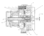
Fig. 2 is a kind of longitudinal sectional drawing that has the scroll-type volume displacement device of doubledirection thrust bearing; Fig. 3 is a kind of schematic representation of rotating driveshaft of the scroll-type volume displacement device that has a doubledirection thrust bearing; See also Fig. 2 and shown in Figure 3, a kind of scroll-type volume displacement device that has doubledirection thrust bearing comprises a main casing 20, one base casings 70; One rotating driveshaft, 40, one fixed scrolls 50 and one are around moving scrollwork 60.Fixed scroll 50 has one first end plate 51, on first end plate 51, is fixed with swirl elements 52, and swirl elements 52 is fixed on it and stretched out thus; Have on one second end plate, 61, the second end plates 61 around moving scrollwork 60 and to be fixed with swirl elements 62, swirl elements 62 fixing its are gone up also and are stretched out thus; First end plate 51 that is provided with swirl elements 52 and second end plate 61 that is provided with swirl elements 62 each other near; Make and be meshing with each other between swirl elements 52 and the swirl elements 62; And swirl elements 52 is butted on respectively on second end plate 61 and first end plate 51 with swirl elements 62, and keeps 180 ° phase angle displacement and equal the radial displacement around moving radius R or.When moving scrollwork 60 is done orbiting with respect to fixed scroll 50, form the air chamber of a sealing between swirl elements 52 and the swirl elements 62 at least, change the volume of air chamber through the slip between first end plate 51 and second end plate, 61 Surface of action.
Through doing around moving scrollwork, can cause the line that the moves contact between the first end plate sidewall and the second end plate sidewall with respect to fixed scroll circle (promptly around moving) at ordinary times.
Fixed scroll 50 and be separately positioned in the main casing 20 around moving scrollwork 60; Come support fixation scrollwork 50 through main casing 20; And the rear end of fixed scroll 50 is fitted in the main casing 20, and base casing 70 is connected with main casing 20, and base casing 70 is over against the rear end around moving scrollwork 60.
One rotating driveshaft 40 comprises a central axis 41; One crankpin 42 and a crankpin 44; Crankpin 42 and crankpin 44 are separately positioned on an end of central axis 41; Central axis 41 runs through the intermediate portion of base casing 70, and has crankpin 42 1 ends near around the rear end of moving scrollwork 60, and the crankpin bearing 260 of crankpin 42 through center driven joint 64 can drive around moving scrollwork 60 does the circular translation (promptly around moving) with respect to fixed scroll 50; Front and back two-part of central axis 41 are not by bearing 33 and 34 supports of bearing; Bearing 33 is separately positioned on base casing 70 with bearing 34; And by 70 supports of base casing; Make central axis 41 be arranged on rotationally in the base casing 70, play effect through bearing 33 and bearing 34 simultaneously central axis 41 location.Between bearing 33 and bearing 34, also have a motor 35, motor 35 is arranged in base casing 70, and by 70 supports of base casing, central axis 41 connects motor 35, makes that central axis 41 can rotate around shaft axis S1-S1 under the driving of motor 35.
Middle body at second end plate 61 has a bearing support 63; Crankpin bearing 260 is installed in bearing support 63; Crankpin 42 is connected with crankpin bearing 260 through center driven joint 64; Crankpin 44 is through driving bearing 65 and be connected around dynamic bearing 261, make central axis 41 respectively with crankpin bearing 260 be connected around dynamic bearing 261.Motor 35 drives central axis 41 rotations; Drive center driven joint 64 and driving bearing 65; And drive crankpin bearing 260 and around dynamic bearing 261; Crankpin bearing 260 drives bearing supports 63 motions and since bearing support 63 with is fixedly connected around moving scrollwork 60, feasible around move scrollwork 60 can according to the motion of bearing support 63 do with respect to fixed scroll 50 around moving.
Has an axial bore 43 at central axis 41 near an end of crankpin bearing 260; Axial bore 43 is positioned near the center line S2-S2 of crankpin 42, and axial bore 43 is used for the centrifugal force that part or all of balance crankshaft pin 42 and crankpin 44 are produced when shaft axis S1-S1 rotates at central axis 41.
On main casing 20, have a suction port 80, at main casing 20 and fixed scroll 50 with between moving scrollwork 60, have an air intake passage 81,, can get into air intake passages 81 through the suction port on the main casing 20 80 when working fluid air for example.Middle part between moving scrollwork 60 and fixed scroll 50 has a central air chamber 82; Between ear end face that moves scrollwork 60 and up-thrust bearing 72, have a pressure air chamber 83, the pressure in the pressure air chamber can be connected with pressure air chamber 83 through passage between the scrollwork 60 at fixed scroll 50 with around moving; The working fluid that gets into air intake passage 81 is inhaled into the pressure air chamber in fixed scroll 50 and formation between moving scrollwork 60; And in moving motion, being compressed around moving scrollwork 60; Be passed to central air chamber 82 then, the relief opening 84 of first end plate, 51 central positions through being positioned at fixed scroll 50 discharges at last.
To have continued to use the patent No. of authorizing the inventor with the ability of radially complying with motion be that ZL200610121150.3 is entitled as the Chinese patent of " improved have the scroll type positive displacement compressor of complying with unsteady scrollwork entirely " in order to provide around moving scrollwork axially in the mechanism's (CSPS structure) that combines of---arthrodia and peripheral crank pin---swing bindiny mechanism that has the centre-driven crankshaft among the present invention.Dimension repeats no more at this.
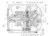
The sectional view of the doubledirection thrust bearing mechanism of the scroll-type volume displacement device that Fig. 4 has a doubledirection thrust bearing for the present invention is a kind of; Fig. 4 A is the schematic representation of the up-thrust bearing of doubledirection thrust bearing mechanism among Fig. 4; Fig. 4 B is the schematic representation of the fixedly thrust-bearing of doubledirection thrust bearing mechanism among Fig. 4; Fig. 4 C is the schematic representation of the lower thrust-bearing of doubledirection thrust bearing mechanism among Fig. 4; See also shown in Fig. 2, Fig. 4, Fig. 4 A, Fig. 4 B and Fig. 4 C, between second end plate 61 that moves scrollwork 60 and base casing 70, have lower thrust-bearing 74, rigid bearing 73 and up-thrust bearing 72.Through driving bearing 65 with drive around dynamic bearing 261 up-thrust bearings 72 and lower thrust-bearing 74 do with around move scrollwork 60 similar around moving.
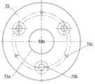
Up-thrust bearing 72 is specially a disc, and the centre of up-thrust bearing 72 has a through hole 72a, is uniformly distributed with three step hole 72b and three tapped hole 72c around the up-thrust bearing 72.
Rigid bearing 73 is specially a disc, has a through hole 73a in the centre of rigid bearing 73, is provided with a step hole 73b with one heart in the periphery of through hole 73a, is uniformly distributed with three sunk screw hole 73c and three hole 73d around the rigid bearing 73; Three sunk screws 77 pass three hole 73c respectively rigid bearing 73 are fixed on the base casing 70.
Lower thrust-bearing 74 is specially a disc, has a through hole 74a in the centre of lower thrust-bearing 74, is evenly equipped with three sunk screw hole 74b and three hole 74c around the lower thrust-bearing 74.
Up-thrust bearing 72, rigid bearing 73 is arranged in order with lower thrust-bearing 74.Three spacers 75 separate up-thrust bearing 72 and lower thrust-bearing 74, make its distance bigger than the thickness of rigid bearing 73; Three sunk screws 76 connect firmly up-thrust bearing 72 is in the same place with lower thrust-bearing 74, and up-thrust bearing 72 and lower thrust-bearing 74 also are in the same place with connecting firmly around dynamic bearing 261, and adopts around the internal diameter of dynamic bearing 261 and driving bearing 65 and to be slidingly matched.The difference of the diameter of the hole 73d of the diameter of spacer 75 and rigid bearing 73 equals the twice around moving radius around moving scrollwork 60; Be around moving diameter, simultaneously the distance of the shaft axis S2-S2 of the shaft axis S1-S1 of crankpin 42 and crankpin 44 also be equal to around move scrollwork 60 around moving radius.When crankpin 44 drives driving bearing 65, drive again around dynamic bearing 261, and finally make up-thrust bearing 72 and lower thrust-bearing 74 do around moving motion, can do axial slip together around dynamic bearing 261, up-thrust bearing 72 and lower thrust-bearing 74 simultaneously.Being installed on 75 of spacers among the 73d of hole plays effectively and prevents that up-thrust bearing 72 and lower thrust-bearing 74 from rotating.
On second end plate 61, have seal element 90 and seal element 93; Seal element 90 can adopt for example lip-type packing or O RunddichtringO etc. with seal element 93; Between the up-thrust bearing 72 and second end plate 61, also have a pressure air chamber 83, through seal element 90 and seal element 93 that pressure air chamber 83 is separated with the peripheral region seal area.When scroll devices started, the elasticity pretightening force of seal element 90 and seal element 93 guaranteed when moving scrollwork 60 is pushed fixed scroll 50 to have slight axial contact between two scrollworks that are meshed.
In the application of vacuum pump, inlet end is in barometric pressure when starting, and exhaust end also is in barometric pressure.Gas pressure in the pressure air chamber 83 is higher than barometric pressure, and the moving scrollwork 60 of opposing connection applies an axial force of (being motor direction) backward.The size of seal element 90 and seal element 93 is selected; Confirmed the area of pressure air chamber 83; The power that the pressed gas of introducing from the compression air chamber of scrollwork acts on around the rear end of moving scrollwork 60 second end plates 61 adds that the elasticity pretightening force that is applied by seal element 90 and seal element 93 surpasses by being compressed the axial separation force that gas applies at the front end around moving scrollwork 60; This axially will push fixed scroll 50 vertically to around moving scrollwork 60 with joint efforts and mesh the slight contact of scrollworks to obtain two, thereby also make the good radial seal of maintenance between the pressure air chamber.The mechanism's (CSPS structure) that combines of---arthrodia and peripheral crank pin---swing bindiny mechanism that has the centre-driven crankshaft among the present invention also makes and radially keeps and the contacting of fixed scroll element 52 around moving swirl elements 62, seals with the tangential of maintenance compression air chamber.Under the gas pressure effect of this moment in pressure air chamber 83, up-thrust bearing 72 is to the rear portion, and promptly motor direction moves and does sliding contact with rigid bearing 73, bears up axial thrust by the latter.
When the scrollwork vacuum pump remains in operation; Suction end pressure progressively descends; Gas pressure in the pressure air chamber is lower than barometric pressure; The pressure below atmospheric pressure gas of introducing from the compression air chamber of scrollwork the power around the rear end of moving scrollwork 60 second end plates 61 of acting on adds that the elasticity pretightening force that is applied by seal element 90 and seal element 93 adds and acts on around the making a concerted effort of the suffered atmospheric pressure of all outer surfaces of the non-sealed gas chamber of moving scrollwork 60, will push fixed scroll 50 vertically to obtain the slight contact of two engagement scrollworks around moving scrollwork 60.Act on this moment up-thrust bearing 72 back sides atmospheric pressure can with up-thrust bearing 72 and lower thrust-bearing 74 forward (fixed scroll direction) push away; This moment, up-thrust bearing 72 moved to the front portion with lower thrust-bearing 74; 73 on the bearing that is fixed stops; And the front of lower thrust-bearing 74 (towards the fixed scroll direction) done sliding contact with the back of rigid bearing 73; Bear up axial thrust by the latter, avoid because the pressure difference between barometric pressure and the vacuum causes the excessive end thrust on the moving scrollwork that acts on.
The present invention provide a kind of have can bear bi-directional axial power around the dynamicthrust bearing.This thrust-bearing can be a sliding bearing, also can be rolling bearing, also can be both mixing.Doubledirection thrust bearing can make scrollwork in compression process or start in the process of operation, when its axial force has bigger change, remains the axial float of disturbance scrollwork and contacts with the axial slight sealing of fixed scroll.
Claims (6)
1. a scroll-type volume displacement device that has doubledirection thrust bearing comprises that a main casing (20), a base casing (70), a rotating driveshaft (40), a fixed scroll (50) and are around moving scrollwork (60);
It is characterized in that; Between second end plate (61) that moves scrollwork (60) and said base casing (70), have lower thrust-bearing (74), rigid bearing (73) and up-thrust bearing (72) said; Said lower thrust-bearing (74) forms pressure air chamber with said second end plate (61); Said up-thrust bearing (72) is connected with said lower thrust-bearing (74); Said rigid bearing (73) is arranged on the bearing support of said base casing (70), and said lower thrust-bearing (74) is done with said around similar the moving around moving of moving scrollwork (60) with said up-thrust bearing (72).
2. according to the said scroll-type volume displacement device that has doubledirection thrust bearing of claim 1, it is characterized in that:
Have a pressure air chamber (83) between said rear end around moving scrollwork (60) and the said up-thrust bearing (72), behind said pressure air chamber (83) the introducing pressure fluid, saidly be pushed to said fixed scroll (50) around moving scrollwork (60).
3. according to the said scroll-type volume displacement device that has doubledirection thrust bearing of claim 1, it is characterized in that:
Said up-thrust bearing (72) and said lower thrust-bearing (74) are respectively near the both ends of the surface of said rigid bearing (73); And connect firmly together; Said up-thrust bearing (72) and said lower thrust-bearing (74) are done under the drive of said rigid bearing (73) around moving motion, and do moving with respect to said rotating driveshaft (40) vertically.
4. according to the said scroll-type volume displacement device that has doubledirection thrust bearing of claim 3, it is characterized in that:
Said up-thrust bearing (72) is a disc, has a through hole (72a) between wherein, is uniformly distributed with three step holes (72b) and three tapped holes (72c) around the said up-thrust bearing (72).
5. according to the said scroll-type volume displacement device that has doubledirection thrust bearing of claim 3, it is characterized in that:
Said rigid bearing (73) is a disc; Has a through hole (73a) wherein; Be provided with a step hole (73b) with one heart in the periphery of said through hole (73a), be uniformly distributed with three sunk screw holes (73c) and three holes (73d) around the said rigid bearing (73).
6. according to the said scroll-type volume displacement device that has doubledirection thrust bearing of claim 3, it is characterized in that:
Said lower thrust-bearing (74) is a disc, has a through hole (74a) between wherein, is uniformly distributed with three sunk screw holes (74b) and three holes (74c) around the said lower thrust-bearing (74).
Priority Applications (2)
| Application Number | Priority Date | Filing Date | Title |
|---|---|---|---|
| CN201110150746.7A CN102817841B (en) | 2011-06-07 | 2011-06-07 | Scroll-type volume displacement device with bidirectional thrust bearings |
| PCT/CN2012/000773 WO2012167611A1 (en) | 2011-06-07 | 2012-06-06 | Scroll type displacement device having bidirectional thrust bearing |
Applications Claiming Priority (1)
| Application Number | Priority Date | Filing Date | Title |
|---|---|---|---|
| CN201110150746.7A CN102817841B (en) | 2011-06-07 | 2011-06-07 | Scroll-type volume displacement device with bidirectional thrust bearings |
Publications (2)
| Publication Number | Publication Date |
|---|---|
| CN102817841A true CN102817841A (en) | 2012-12-12 |
| CN102817841B CN102817841B (en) | 2015-07-08 |
Family
ID=47295427
Family Applications (1)
| Application Number | Title | Priority Date | Filing Date |
|---|---|---|---|
| CN201110150746.7A Active CN102817841B (en) | 2011-06-07 | 2011-06-07 | Scroll-type volume displacement device with bidirectional thrust bearings |
Country Status (2)
| Country | Link |
|---|---|
| CN (1) | CN102817841B (en) |
| WO (1) | WO2012167611A1 (en) |
Cited By (3)
| Publication number | Priority date | Publication date | Assignee | Title |
|---|---|---|---|---|
| CN104343687A (en) * | 2013-07-31 | 2015-02-11 | 思科涡旋科技(杭州)有限公司 | Scroll vacuum pump with magnetofluid horizontal moving sliding thrust bearing and sealing structure |
| CN104500395A (en) * | 2014-12-12 | 2015-04-08 | 沙无埃 | Vortex compressor |
| CN113728164A (en) * | 2019-04-30 | 2021-11-30 | 安捷伦科技有限公司 | Double-sided oil film thrust bearing in scroll pump |
Citations (5)
| Publication number | Priority date | Publication date | Assignee | Title |
|---|---|---|---|---|
| JPH0587129A (en) * | 1991-09-30 | 1993-04-06 | Ntn Corp | Thrust supporting device for turning member |
| CN1150997A (en) * | 1995-11-17 | 1997-06-04 | 倪诗茂 | Positive displacement type vortex fluid compression device with sliding plane thrust bearing |
| CN101008321A (en) * | 2006-01-26 | 2007-08-01 | 倪诗茂 | Improved scroll-type fluid displacement apparatus with fully compliant floating scrolls |
| CN101427029A (en) * | 2006-04-21 | 2009-05-06 | 三电有限公司 | Scroll type fluid machine |
| JP2010048093A (en) * | 2008-08-19 | 2010-03-04 | Nippon Soken Inc | Scroll compressor |
Family Cites Families (4)
| Publication number | Priority date | Publication date | Assignee | Title |
|---|---|---|---|---|
| CN1782424A (en) * | 2004-11-30 | 2006-06-07 | 乐金电子(天津)电器有限公司 | Oil supply structure of scroll compressor |
| JP2008196034A (en) * | 2007-02-15 | 2008-08-28 | Ntn Corp | Thrust bearing |
| JP4859730B2 (en) * | 2007-03-30 | 2012-01-25 | 三菱電機株式会社 | Scroll compressor |
| JP2008286135A (en) * | 2007-05-18 | 2008-11-27 | Denso Corp | Compressor |
-
2011
- 2011-06-07 CN CN201110150746.7A patent/CN102817841B/en active Active
-
2012
- 2012-06-06 WO PCT/CN2012/000773 patent/WO2012167611A1/en not_active Ceased
Patent Citations (5)
| Publication number | Priority date | Publication date | Assignee | Title |
|---|---|---|---|---|
| JPH0587129A (en) * | 1991-09-30 | 1993-04-06 | Ntn Corp | Thrust supporting device for turning member |
| CN1150997A (en) * | 1995-11-17 | 1997-06-04 | 倪诗茂 | Positive displacement type vortex fluid compression device with sliding plane thrust bearing |
| CN101008321A (en) * | 2006-01-26 | 2007-08-01 | 倪诗茂 | Improved scroll-type fluid displacement apparatus with fully compliant floating scrolls |
| CN101427029A (en) * | 2006-04-21 | 2009-05-06 | 三电有限公司 | Scroll type fluid machine |
| JP2010048093A (en) * | 2008-08-19 | 2010-03-04 | Nippon Soken Inc | Scroll compressor |
Non-Patent Citations (3)
| Title |
|---|
| 丁玉炎,姚孟栋: "空调用涡旋式制冷压缩机的新结构", <<流体工程>>, 29 August 1987 (1987-08-29) * |
| 吴建华,束鹏程: "涡旋压缩机的动力分析", <<制冷学报>>, 25 December 1995 (1995-12-25) * |
| 森下悦生,杉原正浩,吴丰: "涡旋压缩机的设计问题", <<压缩机技术>>, 28 August 1988 (1988-08-28) * |
Cited By (6)
| Publication number | Priority date | Publication date | Assignee | Title |
|---|---|---|---|---|
| CN104343687A (en) * | 2013-07-31 | 2015-02-11 | 思科涡旋科技(杭州)有限公司 | Scroll vacuum pump with magnetofluid horizontal moving sliding thrust bearing and sealing structure |
| CN104343687B (en) * | 2013-07-31 | 2016-12-28 | 思科涡旋科技(杭州)有限公司 | There is magnetic fluid translation slide thrust bearing and seal the scroll vacuum pump of structure |
| CN104500395A (en) * | 2014-12-12 | 2015-04-08 | 沙无埃 | Vortex compressor |
| CN113728164A (en) * | 2019-04-30 | 2021-11-30 | 安捷伦科技有限公司 | Double-sided oil film thrust bearing in scroll pump |
| CN113728164B (en) * | 2019-04-30 | 2024-04-02 | 安捷伦科技有限公司 | Double-sided oil film thrust bearing in scroll pump |
| US12098642B2 (en) | 2019-04-30 | 2024-09-24 | Agilent Technologies, Inc. | Double sided oil film thrust bearing in a scroll pump |
Also Published As
| Publication number | Publication date |
|---|---|
| CN102817841B (en) | 2015-07-08 |
| WO2012167611A1 (en) | 2012-12-13 |
Similar Documents
| Publication | Publication Date | Title |
|---|---|---|
| CN102817840B (en) | Scroll-type volume displacement device with orbiting thrust bearing | |
| US8790099B2 (en) | Rotary compressor with synchronous turning between cylinder block and rotor | |
| JP5083401B2 (en) | Scroll compressor | |
| KR101300261B1 (en) | Scroll compressor | |
| US20070172373A1 (en) | Scroll-type fluid displacement apparatus with fully compliant floating scrolls | |
| CN107076143A (en) | Screw compressor | |
| JPS62210279A (en) | Scroll compressor | |
| KR101368396B1 (en) | Scroll compressor | |
| US6758659B2 (en) | Scroll type fluid displacement apparatus with fully compliant floating scrolls | |
| CN106574618B (en) | scroll compressor | |
| CN102817841A (en) | Scroll-type volume displacement device with bidirectional thrust bearings | |
| GB2452379A (en) | Scroll compressor back pressure chamber defined between seals on spaced planes | |
| US20130121864A1 (en) | Scroll compressor | |
| CN105986997B (en) | Scroll compressor having a plurality of scroll members | |
| CN202991488U (en) | Axial flexible sealed vortex compressor | |
| KR100518016B1 (en) | Apparatus preventing reverse revolution for scroll compresser | |
| KR101258090B1 (en) | Scroll compressor | |
| CN100410537C (en) | Suspension type scroll fluid compressor with omnibearing complying structure | |
| CN106151038B (en) | Screw compressor and air conditioner | |
| JP4706892B2 (en) | Scroll fluid machinery | |
| CN201202644Y (en) | Overturn preventing device for vortex compressor | |
| JP2011085132A (en) | Scroll pump with isolation barrier | |
| KR100332791B1 (en) | Counter revolution interruption device for scroll compressor | |
| KR100308284B1 (en) | Scounter revolution interruption device of a scroll compressor | |
| JPH04128580A (en) | Scroll compressor |
Legal Events
| Date | Code | Title | Description |
|---|---|---|---|
| C06 | Publication | ||
| PB01 | Publication | ||
| C10 | Entry into substantive examination | ||
| SE01 | Entry into force of request for substantive examination | ||
| C14 | Grant of patent or utility model | ||
| GR01 | Patent grant | ||
| TR01 | Transfer of patent right | ||
| TR01 | Transfer of patent right |
Effective date of registration: 20190717 Address after: Room 1801, Floor 18, Room 6, Yinhu Innovation Center, No. 9 Fuxian Road, Yinhu Street, Fuyang District, Hangzhou City, Zhejiang Province Patentee after: Hangzhou Sixuan Technology Co., Ltd. Address before: 310051, Hangzhou, Binjiang District, Jiangling Road, No. 6, building 88, building 2 Patentee before: Scroll Laboratories, Inc. |