CN102798790A - Electric leakage sensing apparatus - Google Patents
Electric leakage sensing apparatus Download PDFInfo
- Publication number
- CN102798790A CN102798790A CN2012101592411A CN201210159241A CN102798790A CN 102798790 A CN102798790 A CN 102798790A CN 2012101592411 A CN2012101592411 A CN 2012101592411A CN 201210159241 A CN201210159241 A CN 201210159241A CN 102798790 A CN102798790 A CN 102798790A
- Authority
- CN
- China
- Prior art keywords
- electric leakage
- voltage
- cable
- coupling condenser
- detection
- Prior art date
- Legal status (The legal status is an assumption and is not a legal conclusion. Google has not performed a legal analysis and makes no representation as to the accuracy of the status listed.)
- Pending
Links
Images


Classifications
-
- B—PERFORMING OPERATIONS; TRANSPORTING
- B60—VEHICLES IN GENERAL
- B60L—PROPULSION OF ELECTRICALLY-PROPELLED VEHICLES; SUPPLYING ELECTRIC POWER FOR AUXILIARY EQUIPMENT OF ELECTRICALLY-PROPELLED VEHICLES; ELECTRODYNAMIC BRAKE SYSTEMS FOR VEHICLES IN GENERAL; MAGNETIC SUSPENSION OR LEVITATION FOR VEHICLES; MONITORING OPERATING VARIABLES OF ELECTRICALLY-PROPELLED VEHICLES; ELECTRIC SAFETY DEVICES FOR ELECTRICALLY-PROPELLED VEHICLES
- B60L3/00—Electric devices on electrically-propelled vehicles for safety purposes; Monitoring operating variables, e.g. speed, deceleration or energy consumption
- B60L3/0023—Detecting, eliminating, remedying or compensating for drive train abnormalities, e.g. failures within the drive train
- B60L3/0069—Detecting, eliminating, remedying or compensating for drive train abnormalities, e.g. failures within the drive train relating to the isolation, e.g. ground fault or leak current
-
- B—PERFORMING OPERATIONS; TRANSPORTING
- B60—VEHICLES IN GENERAL
- B60L—PROPULSION OF ELECTRICALLY-PROPELLED VEHICLES; SUPPLYING ELECTRIC POWER FOR AUXILIARY EQUIPMENT OF ELECTRICALLY-PROPELLED VEHICLES; ELECTRODYNAMIC BRAKE SYSTEMS FOR VEHICLES IN GENERAL; MAGNETIC SUSPENSION OR LEVITATION FOR VEHICLES; MONITORING OPERATING VARIABLES OF ELECTRICALLY-PROPELLED VEHICLES; ELECTRIC SAFETY DEVICES FOR ELECTRICALLY-PROPELLED VEHICLES
- B60L3/00—Electric devices on electrically-propelled vehicles for safety purposes; Monitoring operating variables, e.g. speed, deceleration or energy consumption
- B60L3/04—Cutting off the power supply under fault conditions
-
- B—PERFORMING OPERATIONS; TRANSPORTING
- B60—VEHICLES IN GENERAL
- B60L—PROPULSION OF ELECTRICALLY-PROPELLED VEHICLES; SUPPLYING ELECTRIC POWER FOR AUXILIARY EQUIPMENT OF ELECTRICALLY-PROPELLED VEHICLES; ELECTRODYNAMIC BRAKE SYSTEMS FOR VEHICLES IN GENERAL; MAGNETIC SUSPENSION OR LEVITATION FOR VEHICLES; MONITORING OPERATING VARIABLES OF ELECTRICALLY-PROPELLED VEHICLES; ELECTRIC SAFETY DEVICES FOR ELECTRICALLY-PROPELLED VEHICLES
- B60L53/00—Methods of charging batteries, specially adapted for electric vehicles; Charging stations or on-board charging equipment therefor; Exchange of energy storage elements in electric vehicles
-
- G—PHYSICS
- G01—MEASURING; TESTING
- G01R—MEASURING ELECTRIC VARIABLES; MEASURING MAGNETIC VARIABLES
- G01R19/00—Arrangements for measuring currents or voltages or for indicating presence or sign thereof
- G01R19/165—Indicating that current or voltage is either above or below a predetermined value or within or outside a predetermined range of values
-
- G—PHYSICS
- G01—MEASURING; TESTING
- G01R—MEASURING ELECTRIC VARIABLES; MEASURING MAGNETIC VARIABLES
- G01R31/00—Arrangements for testing electric properties; Arrangements for locating electric faults; Arrangements for electrical testing characterised by what is being tested not provided for elsewhere
- G01R31/50—Testing of electric apparatus, lines, cables or components for short-circuits, continuity, leakage current or incorrect line connections
- G01R31/52—Testing for short-circuits, leakage current or ground faults
-
- H—ELECTRICITY
- H02—GENERATION; CONVERSION OR DISTRIBUTION OF ELECTRIC POWER
- H02H—EMERGENCY PROTECTIVE CIRCUIT ARRANGEMENTS
- H02H3/00—Emergency protective circuit arrangements for automatic disconnection directly responsive to an undesired change from normal electric working condition with or without subsequent reconnection ; integrated protection
- H02H3/02—Details
- H02H3/04—Details with warning or supervision in addition to disconnection, e.g. for indicating that protective apparatus has functioned
- H02H3/044—Checking correct functioning of protective arrangements, e.g. by simulating a fault
-
- H—ELECTRICITY
- H02—GENERATION; CONVERSION OR DISTRIBUTION OF ELECTRIC POWER
- H02H—EMERGENCY PROTECTIVE CIRCUIT ARRANGEMENTS
- H02H3/00—Emergency protective circuit arrangements for automatic disconnection directly responsive to an undesired change from normal electric working condition with or without subsequent reconnection ; integrated protection
- H02H3/16—Emergency protective circuit arrangements for automatic disconnection directly responsive to an undesired change from normal electric working condition with or without subsequent reconnection ; integrated protection responsive to fault current to earth, frame or mass
- H02H3/17—Emergency protective circuit arrangements for automatic disconnection directly responsive to an undesired change from normal electric working condition with or without subsequent reconnection ; integrated protection responsive to fault current to earth, frame or mass by means of an auxiliary voltage injected into the installation to be protected
-
- G—PHYSICS
- G01—MEASURING; TESTING
- G01R—MEASURING ELECTRIC VARIABLES; MEASURING MAGNETIC VARIABLES
- G01R31/00—Arrangements for testing electric properties; Arrangements for locating electric faults; Arrangements for electrical testing characterised by what is being tested not provided for elsewhere
- G01R31/005—Testing of electric installations on transport means
- G01R31/006—Testing of electric installations on transport means on road vehicles, e.g. automobiles or trucks
- G01R31/007—Testing of electric installations on transport means on road vehicles, e.g. automobiles or trucks using microprocessors or computers
-
- G—PHYSICS
- G01—MEASURING; TESTING
- G01R—MEASURING ELECTRIC VARIABLES; MEASURING MAGNETIC VARIABLES
- G01R31/00—Arrangements for testing electric properties; Arrangements for locating electric faults; Arrangements for electrical testing characterised by what is being tested not provided for elsewhere
- G01R31/36—Arrangements for testing, measuring or monitoring the electrical condition of accumulators or electric batteries, e.g. capacity or state of charge [SoC]
- G01R31/382—Arrangements for monitoring battery or accumulator variables, e.g. SoC
-
- Y—GENERAL TAGGING OF NEW TECHNOLOGICAL DEVELOPMENTS; GENERAL TAGGING OF CROSS-SECTIONAL TECHNOLOGIES SPANNING OVER SEVERAL SECTIONS OF THE IPC; TECHNICAL SUBJECTS COVERED BY FORMER USPC CROSS-REFERENCE ART COLLECTIONS [XRACs] AND DIGESTS
- Y02—TECHNOLOGIES OR APPLICATIONS FOR MITIGATION OR ADAPTATION AGAINST CLIMATE CHANGE
- Y02T—CLIMATE CHANGE MITIGATION TECHNOLOGIES RELATED TO TRANSPORTATION
- Y02T10/00—Road transport of goods or passengers
- Y02T10/60—Other road transportation technologies with climate change mitigation effect
- Y02T10/70—Energy storage systems for electromobility, e.g. batteries
-
- Y—GENERAL TAGGING OF NEW TECHNOLOGICAL DEVELOPMENTS; GENERAL TAGGING OF CROSS-SECTIONAL TECHNOLOGIES SPANNING OVER SEVERAL SECTIONS OF THE IPC; TECHNICAL SUBJECTS COVERED BY FORMER USPC CROSS-REFERENCE ART COLLECTIONS [XRACs] AND DIGESTS
- Y02—TECHNOLOGIES OR APPLICATIONS FOR MITIGATION OR ADAPTATION AGAINST CLIMATE CHANGE
- Y02T—CLIMATE CHANGE MITIGATION TECHNOLOGIES RELATED TO TRANSPORTATION
- Y02T10/00—Road transport of goods or passengers
- Y02T10/60—Other road transportation technologies with climate change mitigation effect
- Y02T10/7072—Electromobility specific charging systems or methods for batteries, ultracapacitors, supercapacitors or double-layer capacitors
-
- Y—GENERAL TAGGING OF NEW TECHNOLOGICAL DEVELOPMENTS; GENERAL TAGGING OF CROSS-SECTIONAL TECHNOLOGIES SPANNING OVER SEVERAL SECTIONS OF THE IPC; TECHNICAL SUBJECTS COVERED BY FORMER USPC CROSS-REFERENCE ART COLLECTIONS [XRACs] AND DIGESTS
- Y02—TECHNOLOGIES OR APPLICATIONS FOR MITIGATION OR ADAPTATION AGAINST CLIMATE CHANGE
- Y02T—CLIMATE CHANGE MITIGATION TECHNOLOGIES RELATED TO TRANSPORTATION
- Y02T90/00—Enabling technologies or technologies with a potential or indirect contribution to GHG emissions mitigation
- Y02T90/10—Technologies relating to charging of electric vehicles
- Y02T90/14—Plug-in electric vehicles
Landscapes
- Engineering & Computer Science (AREA)
- Power Engineering (AREA)
- Transportation (AREA)
- Mechanical Engineering (AREA)
- Life Sciences & Earth Sciences (AREA)
- Sustainable Development (AREA)
- Sustainable Energy (AREA)
- Physics & Mathematics (AREA)
- General Physics & Mathematics (AREA)
- Testing Of Short-Circuits, Discontinuities, Leakage, Or Incorrect Line Connections (AREA)
- Electric Propulsion And Braking For Vehicles (AREA)
- Emergency Protection Circuit Devices (AREA)
Abstract
The invention provides an electric leakage sensing apparatus which is able to sense an abnormality caused by the disconnection when the cable connecting the electric leakage sensing apparatus and the DC power supply is disconnected. An electric leakage sensing apparatus includes a pulse generator that supplies a pulse to a coupling capacitor (C1), a voltage detector that detects a voltage at the coupling capacitor (C1), an electric leakage determination unit that compares the voltage detected by the voltage detector to a threshold and determines existence or non-existence of an electric leakage of a DC power supply based on a comparison result, a pre-check circuit that puts the DC power supply into a pseudo electric leakage state, a diagnostic unit that diagnoses whether the electric leakage determination unit determines that the electric leakage exists when the DC power supply is put into the pseudo electric leakage state, and terminals (T1, T2) to which cables (W1, W2) are connected. A current route (X) from the pulse generator to the pre-check circuit through the coupling capacitor (C1) and the cables (W1, W2) is formed when the DC power supply is put into the pseudo electric leakage state.
Description
Technical field
The present invention relates to be used for detect the earth detector of the electric leakage of direct supply at for example electric automobile.
Background technology
In electric automobile, the high-tension direct supply that is used for drive motor or mobile unit is installed.The car body electric insulation of this direct supply and ground connection.But, when defective insulation or short circuit etc. take place between direct supply and the car body for a certain reason, flow through electric current the path from direct supply to ground and produce electric leakage.Therefore, set up the earth detector that is used to detect this electric leakage at direct supply.
In earth detector, exist to possess the device that can detect the so-called self-diagnostic function that whether can normally carry out detection of electrical leakage or can detect the burn out detection function of broken string.After put down in writing the earth detector that possesses self-diagnostic function in the patent documentation 1,2 stated.In addition, after put down in writing the earth detector that possesses the burn out detection function in the patent documentation 3 stated.
In patent documentation 1; Between the tie point and ground that detect resistance and insulation resistance, self diagnosis is connected in series with resistance and on-off element, and is provided with identifying unit; Said identifying unit is when self diagnosis moves; Under the state of on-off element for connection, the magnitude of voltage that appears at the tie point that detects resistance and insulation resistance is different under the situation of reference value, is judged to be to detect resistance deterioration or fault.
In patent documentation 2; In following insulating property diagnostic device; Be provided with and produce the analog insulation reduction circuit that identical signal changes when reducing with the insulation against ground resistance of insulation against ground circuit, wherein, said insulating property diagnostic device applies pulse voltage through coupling condenser to the insulation against ground circuit; And according to the leakage current that flows to the insulation against ground circuit size of proportional signal voltage roughly, judge that the insulation of insulation against ground circuit is very denied.
In patent documentation 3, detect in the motor driver of defective insulation in frequency content according to earth leakage current, be provided with: wave forming circuit portion, it exports pulse according to the output of leakage current testing circuit portion and the comparative result of threshold value; And broken string decision circuit portion, not exporting in this wave forming circuit portion under the situation of pulse of preset frequency, this broken string decision circuit portion is judged to be from path between power supply to the defective insulation testing circuit portion broken string has taken place.
Fig. 4 illustrates an example of the existing earth detector that possesses self-diagnostic function.Earth detector 200 possesses CPU1, pulse producer 2, filter circuit 3, pre-detection circuit 4, storer 5, resistance R 1 and coupling condenser C1, C3.CPU1 possesses voltage detection department 6, electric leakage detection unit 7, diagnosing section 8.Filter circuit 3 is made up of resistance R 2 and capacitor C2.Pre-detection circuit 4 is by transistor Q and resistance R 3~R
5 form.The negative side of direct supply 300 (high-voltage battery) is connected with coupling condenser C1, the C3 of earth detector 200 via cable W.The side of the positive electrode of direct supply 300 is connected with motor, mobile unit even load.
The action of earth detector 200 usually the time is following.Charge via 1 couple of coupling condenser C1 of resistance R from the pulse (Fig. 6 (a)) of pulse producer 2 outputs, through this charging, the current potential that P is ordered rises.The current potential that this P is ordered is transfused to CPU1 via filter circuit 3 as input voltage V.The voltage detection department 6 of CPU1 detects the voltage of coupling condenser C1 according to this input voltage V.The voltage of the coupling condenser C1 that detects is called as " detection voltage " at the back.
Do not take place at direct supply 300 under the situation of electric leakage, shown in the solid line of Fig. 5, detect the anxious high rising of voltage.Thereby, during rising to from moment to pulse that t1 pulse constantly descends, detect voltage and surpass threshold value SH.On the other hand, produce under the situation of electric leakage, shown in the dotted line of Fig. 5, detect voltage and slowly rise owing to leak impedance at direct supply 300.Thereby, during from moment to moment t1, detect voltage and be no more than threshold value SH.
Then, the action the during self diagnosis of earth detector 200 is following.Under the situation of carrying out self diagnosis, shown in Fig. 6 (b), the pre-detection request signal is transfused to CPU1.The diagnosing section 8 of CPU1 receives this signal, makes the transistor Q conducting of pre-detection circuit 4, to form simulation electric leakage state.Thereby, shown in the dotted arrow of Fig. 4, form from pulse producer 2 via resistance R 1 and coupling condenser C1, C3 current path Y to pre-detection circuit 4.Thereby through the pulse of pulse producer 2 outputs, coupling condenser C1, C3 all are recharged.Consequently, the P current potential of ordering is that the rising of input voltage V is slow.Thereby like Fig. 6 (c), the detection voltage of coupling condenser C1 becomes less than threshold value SH, and therefore, electric leakage detection unit 7 is judged to be " electric leakage is arranged ".According to this judgement, shown in Fig. 6 (d), from CPU1 output detection of electrical leakage signal.Thereby diagnosing section 8 is judged to be detection of electrical leakage and normally carries out.
But in above-mentioned earth detector 200, the current path Y among Fig. 4 is formed on the inside of earth detector 200.Thereby, even under the situation of cable W broken string, when self diagnosis, also form current path Y, carry out action shown in Figure 6, output detection of electrical leakage signal.That is,, all be judged to be the detection of electrical leakage action in the self diagnosis normally no matter whether cable W breaks.
Yet when cable W broke, earth detector 200 broke off from direct supply 300, therefore, can't carry out original detection of electrical leakage.Thereby although be such ERST and also be judged to be detection of electrical leakage in the self diagnosis and move under the normal situation, earth detector 200 continues action under the state that can not carry out detection of electrical leakage.
[patent documentation 1] TOHKEMY 2005-127821 communique
[patent documentation 2] TOHKEMY 2007-163291 communique
[patent documentation 3] TOHKEMY 2004-361309 communique
Summary of the invention
Problem of the present invention is, even under the situation of the cable break that connects earth detector and direct supply, also can detect by this broken string cause unusually.
The present invention is a kind of earth detector, and wherein, this earth detector possesses: coupling condenser, and the one of which end is connected with direct supply; Pulse producer, its other end to this coupling condenser is supplied with pulse; Voltage detection department, it detects the voltage by the coupling condenser of pulse charge; The electric leakage detection unit, it is detected voltage of this voltage detection department and threshold value relatively, judges that according to this comparative result direct supply has or not electric leakage; The simulation leakage circuit makes direct supply become the electric leakage state to its simulation; Diagnosing section; It becomes under the situation of electric leakage state direct supply through this simulation leakage circuit with simulating; Whether diagnosis electric leakage detection unit has been judged to be electric leakage; Said earth detector is characterised in that also possess: the 1st terminal, and its other end that is used for an end is connected to the 1st cable of direct supply is connected with an end of coupling condenser; With the 2nd terminal, its be used for an end be connected to direct supply the 2nd cable the other end with the simulation leakage circuit be connected.And, direct supply being become under the situation of electric leakage state, form the current path that arrives the simulation leakage circuit from pulse producer via coupling condenser, the 1st terminal, the 1st cable, the 2nd cable and the 2nd terminal through the simulation leakage circuit with simulating.
Like this, via the 1st cable and the 2nd cable, therefore, under the situation of any side of 2 cables or both sides' broken string, this current path does not form from pulse producer to the current path of simulating leakage circuit.Thereby when self diagnosis, the simulation leakage circuit can't form the electric leakage state of simulation, and therefore, the voltage of the coupling condenser that voltage detection department detects presents the variation that is different from the voltage in the simulation electric leakage state.Thereby,, can detect unusual that cable break between power supply and the earth detector causes according to the voltage status of coupling condenser.
Among the present invention, also can between the 2nd terminal and simulation leakage circuit, the 2nd coupling condenser be set.
In addition; Among the present invention; Earth detector can also be provided with burn out detection portion, is used to detect a side of the 1st cable and the 2nd cable or the situation of both sides' broken string, has been provided under the state of drive signal at the simulation leakage circuit; Burn out detection portion is more than the threshold value according to the voltage of the coupling condenser that voltage detection department detected, and detects to be broken string.
In addition, among the present invention, also can be, after the simulation leakage circuit had been provided drive signal, the voltage of coupling condenser be that the above state of threshold value has continued under the situation of certain hour, and burn out detection portion detects and is broken string.
According to the present invention, under the situation of the cable break that connects earth detector and direct supply owing to when self diagnosis, do not form the electric leakage state of simulation, therefore can detect by cable break cause unusually.
Description of drawings
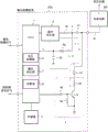
Fig. 1 is the circuit diagram that the earth detector of embodiments of the invention is shown.
Fig. 2 is the sequential chart of the action when being used to explain non-broken string.
Fig. 3 is the sequential chart that is used to explain the action when breaking.
Fig. 4 is the circuit diagram that existing earth detector is shown.
The oscillogram of the detection voltage when Fig. 5 is when electric leakage and non-electric leakage.
Fig. 6 is the sequential chart that is used to explain the action of existing earth detector.
Label declaration
1CPU; 2 pulse producers; 3 filter circuits; 4 pre-detection circuit (simulation leakage circuit); 5 storeies; 6 voltage detection departments; 7 electric leakage detection units; 8 diagnosing section; 9 burn out detection portions; 100 earth detectors; 300 direct supplys; C1, the C3 coupling condenser; T1 terminal (the 1st terminal); T2 terminal (the 2nd terminal); W1 cable (the 1st cable); W2 cable (the 2nd cable); The X current path
Embodiment
With reference to the description of drawings embodiments of the invention.In each figure, give identical label to same section or counterpart.Below, illustrate the situation that applies the present invention to be installed in the earth detector in the electric automobile.
As shown in Figure 1, the negative side of the direct supply 300 (high-voltage battery) of vehicle mounted is connected via cable W1, W2 with earth detector 100.The side of the positive electrode of direct supply 300 is connected with the load of motor, mobile unit etc.Earth detector 100 possesses CPU1, pulse producer 2, filter circuit 3, pre-detection circuit 4, storer 5, resistance R 1, coupling condenser C1, C3 and terminal T1~T5.
CPU1 is configured for controlling the control part of the action of earth detector 100, and it possesses voltage detection department 6, electric leakage detection unit 7, diagnosing section 8 and burn out detection portion 9.In fact, each function of these functional blocks 6~9 is realized by software.Pulse producer 2 generates the pulse of preset frequency according to the instruction from CPU1.Resistance R 1 is connected with the outgoing side of pulse producer 2.Coupling condenser C1 is used for capacitor that direct supply 300 is separated with earth detector 100 direct current ground, and it is connected between resistance R 1 and the terminal T1 (the 1st terminal).
Between pre-detection circuit 4 and terminal T2 (the 2nd terminal), connected coupling condenser C3.Coupling condenser C3 and coupling condenser C1 are same, are to be used for direct current ground to separate direct supply 300 and earth detector 1
00 capacitor is equivalent to the 2nd coupling condenser among the present invention.
The simulation leakage circuit (pseudo electric leakage circuit) that pre-detection circuit 4 constitutes among the present invention, it is made up of transistor Q and resistance R 3~R5.The collector of transistor Q is connected with resistance R 3, and coupling condenser C3 and resistance R 3 are connected in series.The emitter of transistor Q is connected with ground G.The base stage of transistor Q is connected with CPU1 via resistance R 5.Resistance R 4 cross-over connection between the base stage of transistor Q and emitter.
Storer 5 is made up of ROM, RAM etc., and constitutes storage part.The operation program of this storer 5 storage CPU1 is used data with control, and the electric leakage of stating after the storage has or not the threshold value SH that judges usefulness.
In CPU1, voltage detection department 6 is according to being transfused to the input voltage V of CPU1, the voltage of detection coupling condenser C1 from P point via filter circuit 3.
Electric leakage detection unit 7 compares voltage detection department 6 detected voltages and threshold value SH, according to this comparative result, judges that direct supply 300 has or not electric leakage.
Burn out detection portion 9 is according to the state of voltage detection department 6 detected voltages, the situation of the side among detection streamer W1, the W2 or both sides' broken string.
The end of cable W1 (the 1st cable) is connected with the negative pole of direct supply 300.The other end of cable W1 is connected with the terminal T1 of earth detector 100, and is connected with the end of coupling condenser C1 via this terminal T1.
The end of cable W2 (the 2nd cable) is connected with the negative pole of direct supply 300.The other end of cable W2 is connected with the terminal T2 of earth detector 100, and is connected with the end of coupling condenser C3 via this terminal T2.
In fact, for example, the side in idiostatic 2 terminals (omitting diagram) of the end of cable W1 and the negative pole that constitutes direct supply 300 is connected, and the end of cable W2 is connected with the opposing party of these 2 terminals.
Terminal T3~the T5 of earth detector 100 is connected with CPU1.Under the situation that detects electric leakage, from terminal T3 output detection of electrical leakage signal.Under the situation that detects broken string, from terminal T4 output burn out detection signal.Carry out under the situation of self diagnosis, the pre-detection request signal is transfused to terminal T5.For example connecting through behind the certain hour, this pre-detection request signal is being provided by epigyny device (omitting diagram) from ignition switch.
The action of the earth detector of being made up of said structure 100 then, is described.Below, being divided into cable does not have the situation of broken string and the situation of cable break to carry out action specification.
(1) action in cable non-when broken string
At first, with reference to Fig. 2 explain cable W1, W2 all do not have the broken string situation under action.Pulse producer 2 is the pulse of the square wave shown in the cycle output map 2 (a) according to the rules.This pulse is provided for coupling condenser C1 via resistance R 1, and coupling condenser C1 is charged.In addition, in fact, between terminal T1, T2 and car body, have capacitor parasitics, through pulse, capacitor parasitics also is recharged.Through the charging to coupling condenser C1, the current potential that P is ordered rises.The current potential that this P is ordered is transfused to CPU1 via filter circuit 3 as input voltage V.
<do not have the situation of pre-detection request signal>
Pre-detection request signal at Fig. 2 (b) is not transfused under the situation of terminal T5, not from CPU1 to pre-detection circuit 4 output drive signals.Thereby the transistor Q of pre-detection circuit 4 ends.In this state, do not form the represented current path X of dotted arrow of Fig. 1, therefore, through the pulse from pulse producer 2 outputs, only coupling condenser C1 is recharged, and coupling condenser C3 is charging not.
The voltage detection department 6 of CPU1 detects the voltage of coupling condenser C1 according to input voltage V.The detection of this voltage was carried out in the moment that the pulse that offers coupling condenser C1 descends.The voltage of detected coupling condenser C1 is called " detection voltage " at the back.
As shown in Figure 5, electric leakage detection unit 7 relatively by the threshold value SH of storage in voltage detection department 6 detected detection voltages and the storer 5, according to this comparative result, is judged having or not of electric leakage.If do not leak electricity in the direct supply 300, then detect voltage surpass threshold value SH (Fig. 2 (c) a).Thereby electric leakage detection unit 7 is judged to be " not electric leakage ", therefore, and not from CPU1 output detection of electrical leakage signal (Fig. 2 (d)).On the other hand, if produce electric leakage in the direct supply 300, then detect voltage and be no more than threshold value SH (b of Fig. 2 (c)), therefore, electric leakage detection unit 7 is judged to be " electric leakage is arranged ".In this case, from CPU1 output detection of electrical leakage signal (dotted line of Fig. 2).
<have the situation of pre-detection request signal>
During self diagnosis, from the pre-detection request signal of epigyny device to terminal T5 input Fig. 2 (b).And, in same timing from CPU1 to pre-detection circuit 4 output drive signals.This drive signal is the H (High: level signal height) that is used to make transistor Q conducting.Transistor Q is provided for base stage and conducting through this drive signal via resistance R 5.
When transistor Q conducting, shown in the dotted arrow of Fig. 1, form the current path X of pulse producer 2 → resistance R 1 → coupling condenser C1 → terminal T1 → cable W1 → cable W2 → terminal T2 → coupling condenser C3 → pre-detection circuit 4.The emitter of the transistor Q of pre-detection circuit 4 is connected with ground G (car body), therefore, through the conducting of transistor Q, has formed and the actual situation electric leakage state same, simulation that has produced electric leakage between direct supply 300 and car body.
In this simulation electric leakage state, through the pulse of pulse producer 2 outputs, coupling condenser C1 is recharged, and coupling condenser C3 also is recharged.Thereby the current potential that P is ordered is that the rising of input voltage V is slow.Consequently, the detection voltage of coupling condenser C1 is less than threshold value SH (c of Fig. 2 (c)), and the detection unit 7 that therefore leaks electricity is judged to be " electric leakage is arranged ".Then, according to this judgement, shown in Fig. 2 (d) solid line, from CPU1 output detection of electrical leakage signal.Thereby diagnosing section 8 is judged to be detection of electrical leakage and normally carries out.
Then, when in order to finish self diagnosis during not to terminal T5 input pre-detection request signal, disappear in the output of same timed drive signal, the transistor Q of pre-detection circuit 4 becomes once more and ends.Thereby current path X does not form, and simulation electric leakage state is disengaged, and earth detector 100 returns the state before the self diagnosis.
(2) action during cable break
Then, with reference to Fig. 3 the action under the situation of cable W1, W2 broken string is described.In addition, under the situation of cable W2 broken string, electric leakage can be detected, still,, therefore self diagnosis can not be carried out owing to do not form current path X through cable W1.In addition, under the situation of cable W1 broken string, the P point of Fig. 1 breaks off from direct supply 300, thereby can not detect electric leakage, and then, because current path X does not form, can not carry out self diagnosis.Below, illustrate the situation that cable W1 breaks.
<do not have the situation of pre-detection request signal>
Even cable W1 broken string, as previously mentioned since terminal T1 and car body () between have capacitor parasitics, so the charging path from pulse producer 2 to coupling condenser C1 is also kept.But because the broken string of cable W1, coupling condenser C3 is not recharged, therefore, by voltage detection department 6 detected detection voltages surpass threshold value SH (Fig. 3 (c) a).Thereby electric leakage detection unit 7 is judged to be " not having electric leakage ", not from CPU1 output detection of electrical leakage signal (Fig. 3 (d)).
<have the situation of pre-detection request signal>
When self diagnosis, behind terminal T5 input pre-detection request signal (Fig. 3 (b)), as previously mentioned, be used to make the drive signal of transistor Q conducting to 4 outputs of pre-detection circuit from CPU1.But under the situation of cable W1 broken string, the current path X among Fig. 1 does not form and irrelevant with the state of transistor Q.Thereby through the pulse of pulse producer 2, only coupling condenser C1 is recharged, and electric current does not flow to ground G from the resistance R 3 and the transistor Q of coupling condenser C3 through pre-detection circuit 4.That is to say, can't form the electric leakage state of simulation through pre-detection circuit 4.This also is applicable to situation or the cable W1 of cable W2 broken string, the situation of both broken strings of W2.
Thereby the voltage of coupling condenser C1 promptly detects the c that voltage is different from Fig. 2 (c), shown in the d of Fig. 3 (c), surpasses threshold value SH.Thereby electric leakage detection unit 7 is judged to be " not having electric leakage ", and therefore shown in Fig. 3 (d), the detection of electrical leakage signal is not exported.
Under this situation, be provided at pre-detection circuit 4 under the state of drive signal, burn out detection portion 9 becomes the situation more than the threshold value SH according to detecting voltage, detects broken string.In more detail; Burn out detection portion 9 according to the pre-detection request signal behind pre-detection circuit 4 output drive signals; At the detection voltage that voltage detection department 6 is detected is that state more than the threshold value SH has continued under the situation of certain hour (T of Fig. 3 (c)), detects to a side or the both sides of cable W1, W2 broken string has taken place.Then, when detecting the broken string of cable, like Fig. 3 (e), from CPU1 output burn out detection signal by burn out detection portion 9.This burn out detection signal is sent to epigyny device via terminal T4, in epigyny device, carries out abnormality processing (for example, the alarm of output notice broken string).
Like this, in the foregoing description, be divided into 2 with connecting the cable of earth detector 100 with direct supply 300, with cable W1 splicing ear T1 and direct supply 300, and with cable W2 splicing ear T2 and direct supply 300.And, when self diagnosis, form from the current path X of pulse producer 2 via resistance R 2, coupling condenser C1, terminal T1, cable W1, cable W2, terminal T2, coupling condenser C3 to the simulation electric leakage usefulness of pre-detection circuit 4.
Thereby because current path X must be via cable W1, W2, therefore, under the situation of the side in cable W1, W2 or both sides' broken string, current path X does not form, and can not form the electric leakage state of simulation.Thereby, the voltage of coupling condenser C1 appear with simulation electric leakage state in the different variation of voltage, the detection voltage that voltage detection department 6 detects becomes more than the threshold value SH.Based on this, in self diagnosis, can detect by broken string cause unusual.The result is to prevent the disadvantageous generation of earth detector 100 continuation actions under the undetectable state of electric leakage.
Among the present invention, can adopt above-mentioned various embodiment in addition.For example, in the above embodiments, show the example of the filter circuit 3 that setting is made up of resistance R 2 and capacitor C2, still, filter circuit 3 is not required in this invention, can omit yet.In addition, as required, also can add the discharge circuit of the charging charge forced electric discharge that is used to make coupling condenser C1, C3.
In addition, in the above embodiments, in the decline regularly of the pulse of pulse producer 2 output, voltage detection department 6 detects the voltage of coupling condenser C1, and electric leakage detection unit 7 judges having or not of electric leakage, but the invention is not restricted to this.For example, also can be at the predetermined instant before pulse descends, carry out having or not judgement based on the voltage detecting of voltage detection department 6 and based on the electric leakage of the detection unit 7 that leaks electricity.
In addition, in the above embodiments, show the example that constitutes pre-detection circuit 4 by transistor Q and resistance R 4, R5, but also can replace transistor and resistance and adopt relay with coil and contact.
And, in the above embodiments, for example clearly be installed in the earth detector in the electric automobile, but the present invention also can be applied to the earth detector that adopts in the purposes beyond the electric automobile.
Claims (4)
1. earth detector, wherein, this earth detector possesses:
Coupling condenser, the one of which end is connected with direct supply;
Pulse producer, its other end to said coupling condenser is supplied with pulse;
Voltage detection department, it detects the voltage by the said coupling condenser of said pulse charge;
The electric leakage detection unit, detected voltage of its more said voltage detection department and threshold value judge that according to this comparative result said direct supply has or not electric leakage;
The simulation leakage circuit makes said direct supply become the electric leakage state to its simulation;
Diagnosing section, it diagnoses said electric leakage detection unit whether to be judged to be electric leakage said direct supply being become under the situation of electric leakage state through said simulation leakage circuit with simulating,
Said earth detector is characterised in that also possess:
The 1st terminal, its other end that is used for an end is connected to the 1st cable of said direct supply is connected with an end of said coupling condenser; With
The 2nd terminal, its other end that is used for an end is connected to the 2nd cable of said direct supply is connected with said simulation leakage circuit,
Said direct supply is become under the situation of electric leakage state through said simulation leakage circuit with simulating, forming the current path that arrives said simulation leakage circuit from said pulse producer via said coupling condenser, said the 1st terminal, said the 1st cable, said the 2nd cable and said the 2nd terminal.
2. earth detector according to claim 1 is characterized in that,
Between said the 2nd terminal and said simulation leakage circuit, be provided with the 2nd coupling condenser.
3. earth detector according to claim 1 is characterized in that,
Said earth detector also possesses burn out detection portion, and a side of said the 1st cable and said the 2nd cable or the situation of both sides' broken string detect in this burn out detection portion,
Be provided under the state of drive signal at said simulation leakage circuit, said burn out detection portion is the situation more than the said threshold value according to the voltage of the detected said coupling condenser of said voltage detection department, and detecting is broken string.
4. earth detector according to claim 3 is characterized in that,
After said simulation leakage circuit has been provided drive signal, be that state more than the said threshold value has continued under the situation of certain hour at the voltage of said coupling condenser, said burn out detection portion detects and is broken string.
Applications Claiming Priority (2)
| Application Number | Priority Date | Filing Date | Title |
|---|---|---|---|
| JP2011-114977 | 2011-05-23 | ||
| JP2011114977A JP2012242330A (en) | 2011-05-23 | 2011-05-23 | Electric leakage detection device |
Publications (1)
| Publication Number | Publication Date |
|---|---|
| CN102798790A true CN102798790A (en) | 2012-11-28 |
Family
ID=47140547
Family Applications (1)
| Application Number | Title | Priority Date | Filing Date |
|---|---|---|---|
| CN2012101592411A Pending CN102798790A (en) | 2011-05-23 | 2012-05-21 | Electric leakage sensing apparatus |
Country Status (5)
| Country | Link |
|---|---|
| US (1) | US20120299599A1 (en) |
| JP (1) | JP2012242330A (en) |
| KR (1) | KR101291895B1 (en) |
| CN (1) | CN102798790A (en) |
| DE (1) | DE102012104250A1 (en) |
Cited By (6)
| Publication number | Priority date | Publication date | Assignee | Title |
|---|---|---|---|---|
| CN105556320A (en) * | 2013-08-22 | 2016-05-04 | 雷诺股份公司 | Method for detecting a disconnection of a power supply battery of a motor vehicle |
| CN108037470A (en) * | 2017-12-14 | 2018-05-15 | 郑州云海信息技术有限公司 | A kind of D/C power current leakage detection system and detection method |
| CN110133536A (en) * | 2018-02-08 | 2019-08-16 | 奥库瑞特有限公司 | Determine system, the method and apparatus of the index of battery group object internal leakage electric current |
| CN110320431A (en) * | 2018-03-28 | 2019-10-11 | 西门子医疗有限公司 | Earthing effect monitor is isolated |
| CN110631782A (en) * | 2018-06-22 | 2019-12-31 | 三菱电机大楼技术服务株式会社 | Liquid leakage detection device |
| CN113453943A (en) * | 2019-02-19 | 2021-09-28 | 三洋电机株式会社 | Electric leakage detection device and power supply system for vehicle |
Families Citing this family (15)
| Publication number | Priority date | Publication date | Assignee | Title |
|---|---|---|---|---|
| JP2012242330A (en) * | 2011-05-23 | 2012-12-10 | Omron Automotive Electronics Co Ltd | Electric leakage detection device |
| JP2013213750A (en) * | 2012-04-03 | 2013-10-17 | Omron Automotive Electronics Co Ltd | Electrical leak detection device |
| JP6144677B2 (en) * | 2012-06-15 | 2017-06-07 | 日本碍子株式会社 | Secondary battery system and secondary battery failure detection system |
| JP5615335B2 (en) * | 2012-10-15 | 2014-10-29 | オムロンオートモーティブエレクトロニクス株式会社 | Earth leakage detector |
| JP5615342B2 (en) * | 2012-10-19 | 2014-10-29 | オムロンオートモーティブエレクトロニクス株式会社 | Earth leakage detector |
| JP6311859B2 (en) * | 2013-12-25 | 2018-04-18 | 三菱自動車工業株式会社 | Electric vehicle abnormality detection device |
| JP5823007B1 (en) * | 2014-09-25 | 2015-11-25 | 三菱電機株式会社 | Electric leakage detection device for vehicles |
| JP6577270B2 (en) | 2015-07-07 | 2019-09-18 | 株式会社東海理化電機製作所 | Fault diagnosis circuit and fault diagnosis method |
| JP6506644B2 (en) * | 2015-07-09 | 2019-04-24 | 日立オートモティブシステムズ株式会社 | Drive unit |
| US10387284B2 (en) * | 2016-12-07 | 2019-08-20 | The Nielsen Company (Us), Llc | Verifying interconnection between media devices and meters using touch sensing integrated circuits |
| US20190006020A1 (en) * | 2017-06-30 | 2019-01-03 | Sandisk Technologies Llc | Word line leakage detection with common mode tracking |
| JP7100554B2 (en) * | 2018-10-03 | 2022-07-13 | 株式会社Soken | Leakage determination device |
| JP6885994B2 (en) * | 2019-08-23 | 2021-06-16 | ホーチキ株式会社 | Tunnel disaster prevention system |
| JP6857753B1 (en) * | 2020-01-15 | 2021-04-14 | 日本化薬株式会社 | Circuit abnormality diagnostic device, current generator, deployable body injection device for flying object, airbag device for flying object, and cutting device for flying object |
| CN113071322B (en) * | 2021-04-08 | 2022-04-26 | 中车青岛四方机车车辆股份有限公司 | Control method and device of alternating current leakage detection device and railway vehicle |
Citations (3)
| Publication number | Priority date | Publication date | Assignee | Title |
|---|---|---|---|---|
| JP2007068249A (en) * | 2005-08-29 | 2007-03-15 | Hitachi Vehicle Energy Ltd | Leak detector for electric car |
| JP2010181368A (en) * | 2009-02-09 | 2010-08-19 | Mitsubishi Motors Corp | Inspection apparatus of battery pack |
| CN102012473A (en) * | 2009-09-07 | 2011-04-13 | 神钢建设机械株式会社 | Current leakage detector of construction machine |
Family Cites Families (18)
| Publication number | Priority date | Publication date | Assignee | Title |
|---|---|---|---|---|
| JPH0377073A (en) * | 1989-08-18 | 1991-04-02 | Matsushita Electric Ind Co Ltd | Insulation resistance measuring instrument |
| US6700384B2 (en) * | 2000-02-22 | 2004-03-02 | Sanyo Electric Co., Ltd. | Circuit for detecting leakage in power supply |
| JP4133601B2 (en) | 2003-06-06 | 2008-08-13 | 株式会社日本自動車部品総合研究所 | Motor drive device |
| JP4280145B2 (en) | 2003-10-23 | 2009-06-17 | 矢崎総業株式会社 | Insulation resistance drop detector and self-diagnosis method thereof |
| JP2005304148A (en) * | 2004-04-09 | 2005-10-27 | Hitachi Industrial Equipment Systems Co Ltd | Insulation monitoring system |
| US20080197855A1 (en) * | 2005-08-29 | 2008-08-21 | Toyota Jidosha Kabushiki Kaisha | Insulation Resistance Drop Detector and Failure Self-Diagnosis Method for Insulation Resistance Drop Detector |
| JP4572829B2 (en) | 2005-12-14 | 2010-11-04 | 株式会社デンソー | Insulation performance diagnostic device for ground insulation circuit for vehicles |
| WO2008016179A1 (en) * | 2006-08-04 | 2008-02-07 | Toyota Jidosha Kabushiki Kaisha | Insulation resistance determining system, insulation resistance determining apparatus and insulation resistance determining method |
| KR100875748B1 (en) * | 2007-04-17 | 2008-12-26 | 김영철 | Insulation resistance measuring device and method |
| JP5215040B2 (en) * | 2008-05-27 | 2013-06-19 | 株式会社ケーヒン | Earth leakage detection circuit |
| JP5406614B2 (en) * | 2009-07-15 | 2014-02-05 | 矢崎総業株式会社 | Insulation state detector |
| US8749247B2 (en) * | 2009-09-24 | 2014-06-10 | Nissan Motor Co., Ltd. | Apparatus and method for detecting abnormality of high voltage circuit |
| JP5710307B2 (en) * | 2011-02-16 | 2015-04-30 | オムロンオートモーティブエレクトロニクス株式会社 | Earth leakage detector |
| JP5528370B2 (en) * | 2011-02-16 | 2014-06-25 | オムロンオートモーティブエレクトロニクス株式会社 | Leakage detection device, threshold setting method etc. in leakage detection device |
| JP5570455B2 (en) * | 2011-02-16 | 2014-08-13 | オムロンオートモーティブエレクトロニクス株式会社 | Earth leakage detector |
| JP2012242330A (en) * | 2011-05-23 | 2012-12-10 | Omron Automotive Electronics Co Ltd | Electric leakage detection device |
| DE102011050590A1 (en) * | 2011-05-24 | 2012-11-29 | Sma Solar Technology Ag | Insulation monitoring with a test signal of variable frequency |
| JP5414757B2 (en) * | 2011-09-12 | 2014-02-12 | オムロンオートモーティブエレクトロニクス株式会社 | Earth leakage detector |
-
2011
- 2011-05-23 JP JP2011114977A patent/JP2012242330A/en active Pending
-
2012
- 2012-05-16 DE DE102012104250A patent/DE102012104250A1/en not_active Withdrawn
- 2012-05-21 CN CN2012101592411A patent/CN102798790A/en active Pending
- 2012-05-22 US US13/477,878 patent/US20120299599A1/en not_active Abandoned
- 2012-05-22 KR KR1020120054079A patent/KR101291895B1/en not_active IP Right Cessation
Patent Citations (3)
| Publication number | Priority date | Publication date | Assignee | Title |
|---|---|---|---|---|
| JP2007068249A (en) * | 2005-08-29 | 2007-03-15 | Hitachi Vehicle Energy Ltd | Leak detector for electric car |
| JP2010181368A (en) * | 2009-02-09 | 2010-08-19 | Mitsubishi Motors Corp | Inspection apparatus of battery pack |
| CN102012473A (en) * | 2009-09-07 | 2011-04-13 | 神钢建设机械株式会社 | Current leakage detector of construction machine |
Cited By (7)
| Publication number | Priority date | Publication date | Assignee | Title |
|---|---|---|---|---|
| CN105556320A (en) * | 2013-08-22 | 2016-05-04 | 雷诺股份公司 | Method for detecting a disconnection of a power supply battery of a motor vehicle |
| CN108037470A (en) * | 2017-12-14 | 2018-05-15 | 郑州云海信息技术有限公司 | A kind of D/C power current leakage detection system and detection method |
| CN110133536A (en) * | 2018-02-08 | 2019-08-16 | 奥库瑞特有限公司 | Determine system, the method and apparatus of the index of battery group object internal leakage electric current |
| CN110133536B (en) * | 2018-02-08 | 2024-05-28 | 山特维克矿山工程机械有限公司 | System, method and apparatus for determining an indicator of leakage current within a battery entity |
| CN110320431A (en) * | 2018-03-28 | 2019-10-11 | 西门子医疗有限公司 | Earthing effect monitor is isolated |
| CN110631782A (en) * | 2018-06-22 | 2019-12-31 | 三菱电机大楼技术服务株式会社 | Liquid leakage detection device |
| CN113453943A (en) * | 2019-02-19 | 2021-09-28 | 三洋电机株式会社 | Electric leakage detection device and power supply system for vehicle |
Also Published As
| Publication number | Publication date |
|---|---|
| KR20120130725A (en) | 2012-12-03 |
| KR101291895B1 (en) | 2013-07-31 |
| DE102012104250A1 (en) | 2012-11-29 |
| JP2012242330A (en) | 2012-12-10 |
| US20120299599A1 (en) | 2012-11-29 |
Similar Documents
| Publication | Publication Date | Title |
|---|---|---|
| CN102798790A (en) | Electric leakage sensing apparatus | |
| CN102460193B (en) | Connection diagnostic device for ground fault detector | |
| JP5541743B2 (en) | Contactor welding detector | |
| CN104380123B (en) | Earth detector | |
| CN103066636B (en) | Electronic-controlled installation | |
| US10161982B2 (en) | Failure inspection system enabling discrimination between leakage current failure and short-circuit failure | |
| CN102645606B (en) | Electric leakage detection apparatus | |
| CN104569799A (en) | Apparatus and method for diagnosing malfunction of high voltage relay device | |
| CN108859762A (en) | A kind of control system and detection method of power cells for new energy vehicles relay | |
| KR101655377B1 (en) | Apparatus and method for diagnosing failure of battery bus bar | |
| US9260021B2 (en) | Signal generation circuit | |
| CN105572540B (en) | Adaptive electric automobile high-voltage safety fault diagnosis early warning positioning monitoring system | |
| CN103066635B (en) | Electronic-controlled installation | |
| CN106154145A (en) | A kind of fault test set being applied to high-tension battery contactor and fault detection method | |
| CN105765687A (en) | System for determining fixation of relay | |
| CN102112342A (en) | Electric on-board power system | |
| JP2014098681A (en) | Electric leakage detector | |
| US7612576B1 (en) | Method for detecting an inverter hardware failure in an electric power train | |
| CN109799443B (en) | Distributed capacitance self-adaptive insulation detection method based on electric vehicle | |
| CN204462334U (en) | A kind of fault test set being applied to high-tension battery contactor | |
| CN204696641U (en) | A kind of equipment for the protection of high-tension battery using electricity system and the vehicle with this equipment | |
| US11372044B2 (en) | System and method for detecting fault of quick charge relay | |
| CN107533097A (en) | For detecting the method connected by regulation of at least one accumulator and onboard power system | |
| CN106564382B (en) | The high-pressure-loop interlock system and its control method of new-energy automobile | |
| JP6642338B2 (en) | vehicle |
Legal Events
| Date | Code | Title | Description |
|---|---|---|---|
| C06 | Publication | ||
| PB01 | Publication | ||
| C10 | Entry into substantive examination | ||
| SE01 | Entry into force of request for substantive examination | ||
| WD01 | Invention patent application deemed withdrawn after publication |
Application publication date: 20121128 |