CN102797353A - Early-detaching combined template system - Google Patents
Early-detaching combined template system Download PDFInfo
- Publication number
- CN102797353A CN102797353A CN2012103032289A CN201210303228A CN102797353A CN 102797353 A CN102797353 A CN 102797353A CN 2012103032289 A CN2012103032289 A CN 2012103032289A CN 201210303228 A CN201210303228 A CN 201210303228A CN 102797353 A CN102797353 A CN 102797353A
- Authority
- CN
- China
- Prior art keywords
- carriage
- template
- main body
- early
- open
- Prior art date
- Legal status (The legal status is an assumption and is not a legal conclusion. Google has not performed a legal analysis and makes no representation as to the accuracy of the status listed.)
- Granted
Links
Images


Classifications
-
- E—FIXED CONSTRUCTIONS
- E04—BUILDING
- E04G—SCAFFOLDING; FORMS; SHUTTERING; BUILDING IMPLEMENTS OR AIDS, OR THEIR USE; HANDLING BUILDING MATERIALS ON THE SITE; REPAIRING, BREAKING-UP OR OTHER WORK ON EXISTING BUILDINGS
- E04G11/00—Forms, shutterings, or falsework for making walls, floors, ceilings, or roofs
- E04G11/36—Forms, shutterings, or falsework for making walls, floors, ceilings, or roofs for floors, ceilings, or roofs of plane or curved surfaces end formpanels for floor shutterings
- E04G11/48—Supporting structures for shutterings or frames for floors or roofs
- E04G11/486—Dropheads supporting the concrete after removal of the shuttering; Connecting means on beams specially adapted for dropheads
-
- E—FIXED CONSTRUCTIONS
- E04—BUILDING
- E04G—SCAFFOLDING; FORMS; SHUTTERING; BUILDING IMPLEMENTS OR AIDS, OR THEIR USE; HANDLING BUILDING MATERIALS ON THE SITE; REPAIRING, BREAKING-UP OR OTHER WORK ON EXISTING BUILDINGS
- E04G11/00—Forms, shutterings, or falsework for making walls, floors, ceilings, or roofs
- E04G11/36—Forms, shutterings, or falsework for making walls, floors, ceilings, or roofs for floors, ceilings, or roofs of plane or curved surfaces end formpanels for floor shutterings
- E04G11/38—Forms, shutterings, or falsework for making walls, floors, ceilings, or roofs for floors, ceilings, or roofs of plane or curved surfaces end formpanels for floor shutterings for plane ceilings of concrete
-
- E—FIXED CONSTRUCTIONS
- E04—BUILDING
- E04G—SCAFFOLDING; FORMS; SHUTTERING; BUILDING IMPLEMENTS OR AIDS, OR THEIR USE; HANDLING BUILDING MATERIALS ON THE SITE; REPAIRING, BREAKING-UP OR OTHER WORK ON EXISTING BUILDINGS
- E04G11/00—Forms, shutterings, or falsework for making walls, floors, ceilings, or roofs
- E04G11/36—Forms, shutterings, or falsework for making walls, floors, ceilings, or roofs for floors, ceilings, or roofs of plane or curved surfaces end formpanels for floor shutterings
- E04G11/48—Supporting structures for shutterings or frames for floors or roofs
- E04G11/50—Girders, beams, or the like as supporting members for forms
Landscapes
- Engineering & Computer Science (AREA)
- Architecture (AREA)
- Mechanical Engineering (AREA)
- Civil Engineering (AREA)
- Structural Engineering (AREA)
- Forms Removed On Construction Sites Or Auxiliary Members Thereof (AREA)
- Conveying And Assembling Of Building Elements In Situ (AREA)
Abstract
The invention discloses an early-detaching combined template system, comprising a plurality of support pillars and a template assembly. An early-detaching mechanism is arranged on each support pillar, and a top plate and a bracket of the early-detaching mechanism are both in right angle quadrilateral shapes. The brackets of a plurality of early-detaching mechanisms support the template assembly, and the top plates of the plurality of early-detaching mechanisms and the template assembly form a lower support mould of a pouring body. The template assembly comprises a plurality of rectangular beam components and plurality of rectangular template components, wherein the beam components are supported on the brackets, and cross convex-concave lap joint and matching structures are formed between the beam components and the brackets. The plurality of beam components form at least one right angle quadrilateral frame through the brackets, and the template components are positioned in the right angle quadrilateral frame formed by the beam components. A convex-concave matching and lap joint structure is formed between the end part of each template component and the side part of each beam component. The early-detaching combined template system has the beneficial effects that for building and detaching the templates, labor intensity is low, the efficiency is high, the supporting stability is good, use is safe, and force for transition and transport is saved.
Description
Technical field
The present invention relates to a kind of early-dismantling formwork system, particularly a kind of being provided with torn the gang form system morning of early tearing mechanism open open.
Background technology
Early-dismantling formwork system is to be used for the support system that comprises scaffold and template that concrete, concrete steel building or structure are built, the soffit formwork that it forms casting beams or plate through the top board and the form assembly of support column.Early-dismantling mechanism is arranged on the support column in the early-dismantling formwork system, and early-dismantling mechanism is used for template and supports.When casting beams or plate are cured to a certain degree, realize dismounting through early tearing mechanism open to template, casting beams or plate are continued to support to and can be removed fully by the top board of support column.The template of tearing open morning is used for changeing layer or transition, and to shorten or to shift to an earlier date the duration, the construction labor productivity of raising simultaneously, can reduce template and drop into quantity, reduces construction cost.Template all need be made into standard form by setting specification usually, connects through bolt when building or other fastening means realize interconnecting between standard forms, and guaranteeing intensity and safe in utilization, this mode of building seriously restricts template, and to build efficient low.For efficient is built in raising, the template specification size all can receive certain limitation usually.The standard form that for example is used for the system of early tearing open all need be made into the standard form of big specification usually, to reduce support column and the quantity that is provided with of early tearing mechanism open, reduce form cost usefulness, but there is the big deficiency of operator's labour intensity in it.Therefore, for enterprise in charge of construction, labour intensity template support strength height, safety low, that built are taken and tear the efficient height open, built to template is well the common target of pursuing of industry.
Summary of the invention
The object of the invention is exactly the deficiency to prior art, provide a kind of take tear the efficient height open, labour intensity is low, and tears the gang form system morning that support strength is high, safety is good open.
For realizing above-mentioned purpose, the present invention adopts following technical scheme:
Tear the gang form system a kind of morning open; Comprise a plurality of support columns, template assembly; Support column is provided with early tears mechanism open, early tears the top board and all rectangular quadrangle of carriage of mechanism open, tears the support of the bracket-shaped paired template assembly of mechanism a plurality of morning open; Top board and the template assembly of tearing mechanism a plurality of morning open form the following formwork of building body; Said template assembly is made up of the beam parts of a plurality of rectangles and the form element of a plurality of rectangles, and the beam member supporting is formed with the overlap joint fit structure that the cross convex-concave cooperates between beam parts and the carriage on said carriage; Said a plurality of beam parts form at least one right angle quadrilateral frame through carriage, and form element is positioned at by the beam parts and forms the right angle quadrilateral frame, are formed with the bridging arrangement that convex-concave cooperates between form element end and the beam parts sidepiece.
Adopt the present invention of aforementioned techniques scheme; Because template assembly is made up of beam parts the right angle quadrilateral frame that constitutes and the form element of being located at a plurality of rectangles in the framework of a plurality of rectangles; Make template assembly form combining structure; Therefore, the single-piece of beam parts and form element single-piece is in light weight, can greatly reduce template and take the labour intensity of tearing open; Simultaneously be formed with the overlap joint fit structure that the cross convex-concave cooperates between beam parts and the carriage; Be formed with the bridging arrangement that convex-concave cooperates between form element and the beam parts; Building of template do not need bolt or other securing members to connect, and it is taken and tears the efficient height open, and the overlap joint fit structure that the cross convex-concave cooperates can make direction accurate positioning in length and breadth between beam parts and the carriage; And guarantee that the beam parts do not produce horizontal sliding with carriage; Be formed with the right angle quadrilateral frame that bridging arrangement that convex-concave cooperates and a plurality of beam parts form between beam parts and the form element and form the location in the form element horizontal plane jointly, guarantee form element with beam parts generation horizontal sliding, therefore; The template of being built has enough bulk strengths, and is safe in utilization.In addition, because template assembly is combined to form by many, therefore, the single-piece volume is little, is beneficial to save the transition transport power.
The part that the part that optimized technical scheme, said bridging arrangement are located at the form element end can be located at carriage with the overlap joint fit structure that said cross convex-concave cooperates forms convex-concave and is connected.Like this, form a large rectangle framework with regard to six and above even number early-dismantling mechanism and even number beam parts capable of using, at this moment; Outside most of form element overlaps on the beam parts; A small amount of form element overlap joint is on the carriage of early-dismantling mechanism, to reduce the quantity of setting up of beam parts, therefore; The combining structure form of following formwork is flexible, further improves template and sets up and remove efficient.
Further optimized technical scheme, said beam parts comprise the beam main body, and beam main body two ends are fixedly connected with a beam-ends respectively, and beam main body and two beam-ends have been combined to form rectangle frame, are provided with the padding girder by the beam body supports in the rectangle frame; Said form element comprises the template frame, and template frame two ends are fixedly connected with a template frame end plate respectively, and template frame and two template frame end plates form rectangular frame, in rectangular frame, is provided with the panel that is supported by the template frame; Said bridging arrangement is located between template frame end plate and the beam main body; The overlap joint fit structure that said cross convex-concave cooperates is located between the carriage of beam-ends and said early-dismantling mechanism; Said bridging arrangement is located between beam main body and the template frame end plate.Beam parts and form element all are combining structure, make things convenient for processing and manufacturing, are beneficial to the reduction manufacturing cost.
Optimized technical scheme further, said beam main body is made up of lower body and upper body, lower body is the box beam structure, upper body is Π shape structure, the Π shape opening of upper body up, Π shape opening is used to be provided with said padding girder; Said beam-ends is made up of end plate and grafting body; The two side of the end plate of two beam-ends and said beam main body Π shape is formed for the rectangular shaped rim of said padding girder location; The grafting body stretches into the beam body interior and forms plug-in type and cooperate from the end, beam-ends is formed a fixed connection through screw or rivet and said beam main body by the grafting body; Template frame bottom is case structure, and the both sides, casing upper end of template frame extend upward the baffle plate that is useful on said panel located lateral; Said template frame end plate is made up of vertical plate and connected structure, and two vertical plate form, and connected structure stretches into the inner plug-in type that forms of template frame and cooperates from the end, and template frame end plate is formed a fixed connection through screw or rivet and template frame by connected structure; Said bridging arrangement is located between the lower body and template frame end plate of beam main body.Beam main body, beam-ends, template frame and template frame end plate all can adopt aluminium alloy extruded molding mode processing; Perhaps beam main body and template frame adopt the aluminium alloy extrusions manufacturing of extrusion modling; Can greatly improve working (machining) efficiency; Shorten the template manufacturing cycle, and be beneficial to and alleviate template weight, reduce and set up and dismantle labour intensity.Certainly, padding girder adopts flitch to be fixed by screw or adhesive means and beam main body usually, and panel can adopt veneer or composite plate to fix through screw connection, riveted joint or bonding way and template frame.Its selection and connected mode have bigger flexibility, with template strength meet the demands, light, principle choose reasonable such as mounting or dismounting are convenient, cost is low.
Further again optimized technical scheme, the overlap joint fit structure that said cross convex-concave cooperates comprise the fin that is located at the carriage upper surface and are located at the draw-in groove on the beam-ends end plate that fin is positioned on the periphery edge of carriage, fin middle part disconnection formation one groove; The channel that to the curved boom that extend below and end plate lateral surface between constitute of said draw-in groove for being provided with by the end plate lateral surface, curved boom middle part are provided with the column that extends to the end plate side, and column can be in the top insertion groove of the fin of carriage; Said beam main body is by the beam main body that stretches into draw-in groove or be supported on the curved boom support on the carriage, also can be supported simultaneously by the two.Therefore, column and draw-in groove form cross structure, and fin and groove form cross structure; Fin forms convex-concave with draw-in groove and cooperates; Column and groove form the convex-concave fit structure, and the beam main body adopts overlapping mode directly to overlap on carriage, guarantee simple in structure, easy to process.Certainly, column also can be located on the carriage, is connected the fin middle part, and the curved boom middle part forms groove, cooperates bridging arrangement to form criss-cross convex-concave; The cross fins that also can between the lower surface of beam-ends and carriage upper surface, form the cross draw-in groove and cooperate with it etc., its form of structure is flexible.
Further again optimized technical scheme; Said bridging arrangement is formed with the overlap joint seamed edge by supporting seamed edge; The support seamed edge overhangs on beam lower body part casing side and extends upward; The overlap joint seamed edge overhangs on the vertical plate outer face of template frame end plate and to extending below, supports seamed edge and overlap joint seamed edge mutual dislocation; Said form element passes through to support seamed edge or/and the overlap joint seamed edge overlaps on the beam main body of said beam parts; When said beam parts were connected on the said carriage, the fin that is set in parallel with said beam main body on the carriage constituted the extension of support seamed edge on carriage.Guarantee that form element both can overlap on the beam main body, also can overlap on carriage, set up quantity to reduce the beam parts.
Further optimized technical scheme is torn mechanism open and also comprise base plate, pillar said morning, and pillar is located between base plate and the said top board; Said carriage is through being connected on the pillar to the guide pin bushing slip cap that extends below; The carriage below is provided with can be with the carriage support cover of its picking-up; The carriage support puts and is provided with the transmission of torque structure that is used to make its rotation, and the guide pin bushing tube wall of said carriage is provided with vertically and runs through the guide groove of its pipe thickness; Said carriage support cover loose collar is enclosed within the periphery of the guide pin bushing of carriage, and the tube wall of carriage support cover is provided with the chute that extends upward and run through its pipe thickness along tube wall, and the chute bottom is provided with horizontal segment; Traverses fixed has bearing pin on the said pillar, and a part of matched in clearance of bearing pin is in the guide groove of said guide pin bushing; Bearing pin has the part of stretching out from guide groove; The part matched in clearance that bearing pin stretches out from guide groove is in the chute of said carriage support cover; When the part that bearing pin stretches out from guide groove is positioned at the chute horizontal segment; Carriage is supported by carriage support cover, and the guide groove on the carriage guide pin bushing tube wall is cooperated with bearing pin by its bottom; Said base plate lower end is extended with guide peg, and guide peg is provided with gathering sill, and guide peg stretches in the pore of said support column upper end, and support column is provided with through the gathering sill restriction and early tears the guide finger that mechanism rotates open.
When the carriage support is overlapped after bearing pin moves up or moves setpoint distance, carriage is supported by carriage support cover and moves up synchronously with carriage support cover; The part that is positioned at chute when bearing pin is when chute is positioned at the horizontal segment of chute lower end, and carriage support cover is supported by bearing pin, and carriage and template assembly reach setting height.When early tearing open; Through external force carriage support cover is formed driving torque and make its rotation; Making ascent stage of the chute of carriage support cover align bearing pin causes carriage support cover to lose support; Carriage and carriage support cover and template under action of gravity, carriage is with the landing downwards rapidly synchronously of carriage support cover, thereby realizes early-dismantling.The support that the length of chute horizontal segment only need satisfy bearing pin formation favorable and stable gets final product, and therefore, when early tearing open, carriage support cover only needs the minimum angle of rotation can accomplish the operation of early tearing open, need not rotate a complete circle or many circles, so it early tears the efficient height open.Simultaneously; The form of structure that the carriage support is arranged with is used to make the transmission of torque structure of its rotation can adopt special tool to pull; As form structures such as flat side, the outline structure identical, spanner groove, driving hole in carriage support cover periphery, utilize special-purpose pulling tool to pull its rotation with nut or bolt head; Also can adopt the form of cantilever, knock the cantilever far-end and make its rotation through beaing the instrument tangential, its form of structure is flexible.Because the percussion power direction when the cantilever far-end is knocked in the tangential is away from pillar axes, and therefore percussion power, has significantly reduced the influence to support system stability also much smaller than the percussion power of prior art.
Being provided with of chute ascent stage can adopt spiral to rise or straight line rising mode in the carriage support cover of this programme, and when adopting spiral rising mode, the size of its lead angle must satisfy the principle that does not constitute self-locking between carriage support cover and the bearing pin.The size decision carriage support cover of lead angle and the decrease speed of carriage, lead angle is big more, and its decrease speed is fast more, and downslide is impacted big more, during actual the use, needs to weigh the pros and cons of the two.When lead angle reaches 90 when spending, its chute ascent stage forms vertical rising mode, its have easy to process, make beneficial effect simple, low cost of manufacture.But the decline mode of carriage support cover and carriage is basically near freely falling body decline state, in case of necessity, and impact mitigation measure with due regard to.
Optimized technical scheme, said bearing pin are provided with two, and two bearing pins run through pillar respectively and form right-angled intersection with pillar, two bearing pins along boom shaft to mutual dislocation; The chute that guide groove on the said guide pin bushing and carriage support put is equipped with four.When improving stability of strutting system, guarantee that carriage support cover has enough intensity, to guarantee having enough application life.
Optimized technical scheme, said base plate lower end is extended with guide peg, and guide peg is provided with gathering sill.Be convenient to be installed at the steel pipe top of the scaffold of setting up by common steel tube; Early tear the form bracing system of mechanism open ordinary construction scaffold form bracing system is converted to have; Only need guide peg and steel tube inner hole to form matched in clearance; The alignment pin that the rotation of restricted guidance bar is set on steel pipe top gets final product, and the setting of guide peg is beneficial to the stability that improves support system.
Further optimized technical scheme; Be formed with external screw thread on the periphery of a part of length of said guide peg; Guide peg is combined with through external screw thread on the periphery of a part of length of the said guide peg of nut and is formed with external screw thread; Guide peg is combined with nut through external screw thread, and nut support is on said support column top.Be convenient to adjust the height of plate support system.During use, pass through nut support on the steel pipe upper surface of steel pipe support column with early tearing mechanism open, swivel nut moves up and down guide peg, can make the top board height reach desired height and get final product.
The invention has the beneficial effects as follows that template is taken and torn that labour intensity is low, efficient is high open, stability of strutting system is good, safe in utilization, and the transition transport power is saved.
Description of drawings
Fig. 1 is a structural representation axonometric drawing of the present invention.
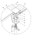
Fig. 2 is the A portion enlarged drawing among Fig. 1 of the present invention.
Fig. 3 is a structural representation axonometric drawing of early tearing the carriage 8 of mechanism among the present invention open.
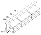
Fig. 4 is the structural representation axonometric drawing of central sill parts 14 of the present invention.
Fig. 5 is that B among Fig. 4 of the present invention is to view.
Fig. 6 is the structural representation axonometric drawing of central sill main body 141 of the present invention.
Fig. 7 is that C among Fig. 6 of the present invention is to view.
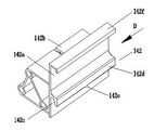
Fig. 8 is the structural representation axonometric drawing of beam-ends 142 among the present invention.
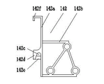
Fig. 9 is that D among Fig. 8 of the present invention is to view.
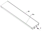
Figure 10 is the structural representation axonometric drawing of form element 15 among the present invention.
Figure 11 is that E among Figure 10 of the present invention is to view.
Figure 12 is the structural representation axonometric drawing of template frame 151 among the present invention.
Figure 13 is that F among Figure 12 of the present invention is to view.
Figure 14 is the structural representation axonometric drawing of template frame end plate 152 among the present invention.
Figure 15 is that G among Figure 14 of the present invention is to view.
Figure 16 early tears the structural representation axonometric drawing of mechanism open among the present invention.
Figure 17 early tears the structural representation axonometric drawing of the main part of mechanism open among the present invention, and carriage 8 is positioned at the state of limes superiors position.
Figure 18 is a part-structure signal axonometric drawing of early tearing mechanism among the present invention open.
Figure 19 is a structural representation axonometric drawing of early tearing the carriage support cover 9 of mechanism among the present invention open.
Figure 20 early tears the structural representation axonometric drawing of the main part of mechanism open among the present invention, and carriage 8 is positioned at the state of limit inferior position.
The specific embodiment
Below in conjunction with accompanying drawing the present invention is further described, but does not therefore limit the present invention among the described scope of embodiments.
Referring to Fig. 1, Fig. 2, Fig. 3, tear the gang form system a kind of morning open, comprises a plurality of support column 13, template assembly; Support column 13 is provided with early tears mechanism open; Early tear the top board 6 and all rectangular quadrangle of carriage 8 of mechanism open, tear the support of carriage 8 formation of mechanism to template assembly a plurality of morning open, the top board 6 of tearing mechanism a plurality of morning open forms the following formwork of building body with template assembly; It is characterized in that; Said template assembly is made up of the form element 15 of the beam parts of a plurality of rectangles 14 and a plurality of rectangles, and beam parts 14 are supported on the said carriage 8, is formed with the overlap joint fit structure that the cross convex-concave cooperates between beam parts 14 and the carriage 8; Said a plurality of beam parts 14 form at least one right angle quadrilateral frame through carriage 8, and form element 15 is positioned at by beam parts 14 and forms the right angle quadrilateral frame, are formed with the bridging arrangement that convex-concave cooperates between form element 15 ends and beam parts 14 sidepieces.
The part that the part that said bridging arrangement is located at form element 15 ends can be located at carriage 8 with the overlap joint fit structure that said cross convex-concave cooperates forms convex-concave and is connected.
Referring to Fig. 4, Fig. 5, Figure 10, Figure 11; Said beam parts 14 comprise beam main body 141; Beam main body 141 two ends are fixedly connected with a beam-ends 142 respectively, and beam main body 141 and two beam-ends 142 have been combined to form rectangle frame, are provided with the padding girder 143 that is supported by beam main body 141 in the rectangle frame; Said form element 15 comprises template frame 151, and template frame 151 two ends are fixedly connected with a template frame end plate 152 respectively, and template frame 151 and two template frame end plates 152 form rectangular frame, in rectangular frame, are provided with the panel 153 that is supported by template frame 151; Said bridging arrangement is located between template frame end plate 152 and the beam main body 141; The overlap joint fit structure that said cross convex-concave cooperates is located between the carriage 8 of beam-ends 142 and said early-dismantling mechanism; Said bridging arrangement is located between beam main body 141 and the template frame end plate 152.
Referring to Fig. 6, Fig. 7, Figure 12, Figure 13, Figure 14, Figure 15; Said beam main body 141 is made up of lower body and upper body, and lower body is the box beam structure, and upper body is Π shape structure; The Π shape opening of upper body up, Π shape opening is used to be provided with said padding girder 143; Said beam-ends 142 is made up of end plate 142a and grafting body 142b; The two side of the end plate 142a of two beam-ends 142 and said beam main body 141 Π shapes is formed for the rectangular shaped rim of said padding girder 143 location; Grafting body 142b stretches into the inner plug-in types that form of beam main body 141 and cooperates from the end, beam-ends 142 is formed a fixed connection through screw or rivet and said beam main body 141 by grafting body 142b; Said template frame 151 bottoms are case structure, and the both sides, casing upper end of template frame 151 extend upward the baffle plate 151a that is useful on said panel 153 located lateral; Said template frame end plate 152 is made up of vertical plate 152a and connected structure 152b; Two vertical plate 152a form; Connected structure 152b stretches into the inner plug-in types that form of template frame 151 and cooperates from the end, template frame end plate 152 is formed a fixed connection through screw or rivet and template frame 151 by connected structure 152b; Said bridging arrangement is located between the lower body and template frame end plate 152 of beam main body 141.
The casing lower surface of said beam main body 141 is provided with two T word stiffening girder 141b, and the Π shape sidewall on beam main body 141 tops is provided with outside bending reinforcement 141c; The end plate 142a upper end of said beam-ends 142 is provided with outside bending reinforcing section 142f, and the casing lower surface of said template frame 151 is provided with four beam 151b of T word group; The vertical plate 152a upper end of said template frame end plate 152 is provided with the stiffened edge 152d of outside bending.
Referring to Fig. 3; Fig. 8, Fig. 9; The overlap joint fit structure that said cross convex-concave cooperates comprises the fin 83 that is located on carriage 8 upper surfaces and is located at the draw-in groove 142c on the beam-ends 142 end plate 142a that fin 83 is positioned on the periphery edge of carriage 8, fin 83 middle parts disconnection formation one groove 84; The channel that to the curved boom 142d that extend below and end plate 142a lateral surface between constitute of said draw-in groove 142c for being provided with by end plate 142a lateral surface; Curved boom 142d middle part is provided with the column 142e that extends to end plate 142a side, and column 142e can insert in the groove 84 from the top of the fin 83 of carriage 8; Said beam main body 141 by the beam main body 141 that stretches into draw-in groove 142c or/and the curved boom 142d that is supported on the carriage 8 support.
Referring to Fig. 6, Fig. 7, Figure 14, Figure 15; Said bridging arrangement is formed with overlap joint seamed edge 152c by supporting seamed edge 141a; Support seamed edge 141a overhangs on beam main body 141 lower part box sides and extends upward; Overlap joint seamed edge 152c overhangs on the vertical plate 152a outer face of template frame end plate 152 and to extending below, supports seamed edge 141a and overlap joint seamed edge 152c mutual dislocation; Said form element 15 passes through to support seamed edge 141a or/and overlap joint seamed edge 152c overlaps on the beam main body 141 of said beam parts 14; Be connected 8 last times of said carriage at said beam parts 14, the fin 83 that is set in parallel with said beam main body 141 on the carriage 8 constitutes and supports the extensions of seamed edge 141a on carriage 8.
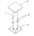
Referring to Fig. 1, Figure 16, Figure 17, Figure 18, Figure 19, Figure 20, to tear mechanism said morning open and also comprise base plate 5, pillar 7, pillar 7 is located between base plate 5 and the said top board 6; Said carriage 8 is through being connected on the pillar 7 to the guide pin bushing that extends below 81 slip caps; Carriage 8 belows are provided with can be with the carriage support cover 9 of its picking-up; Carriage support cover 9 is provided with the support arm 9a that is used to make its rotation, and guide pin bushing 81 tube walls of said carriage 8 are provided with vertically and run through the guide groove 82 of its pipe thickness; The periphery that 9 loose collars are enclosed within the guide pin bushing 81 of carriage 8 is overlapped in said carriage support, and the tube wall of carriage support cover 9 is provided with the chute 91 that extends upward and run through its pipe thickness along tube wall, and chute 91 bottoms are provided with horizontal segment; Traverses fixed has bearing pin 10 on the said pillar 7, and a part of matched in clearance of bearing pin 10 is in the guide groove 82 of said guide pin bushing 81; Bearing pin 10 has the part of stretching out from guide groove 82; The part matched in clearance that bearing pin 10 stretches out from guide groove 82 is in the chute 91 of said carriage support cover 9; When the part that bearing pin 10 stretches out from guide groove 82 is positioned at chute 91 horizontal segments; Carriage 8 is supported by carriage support cover 9, and the guide groove 82 on carriage 8 guide pin bushings 81 tube walls is cooperated with bearing pin 10 by its bottom; Said base plate 5 lower ends are extended with guide peg 11, and guide peg 11 is provided with gathering sill 11a, and guide peg 11 stretches in the pore of said support column 13 upper ends, and support column 13 is provided with through gathering sill 11a restriction and early tears the guide finger 131 that mechanism rotates open.
Be formed with external screw thread on the periphery of a part of length of said guide peg 11; Guide peg 11 is combined with nut 12 through external screw thread; Nut 12 is supported on said support column 13 tops, and the pivoted arm 12a that overhang on the nut 12 is convenient to external force and is acted on nut 12 is rotated.
The section of extending upward of the chute 91 of said carriage support cover 9 extends upward along the vertical direction of its tube wall.
Said bearing pin 10 is provided with two, and two bearing pins 10 run through pillar 7 respectively and form right-angled intersection with pillar 7, and two bearing pins 10 are along pillar 7 axial mutual dislocation; Guide groove 82 on the said guide pin bushing 81 is equipped with four with the chute 91 that the carriage support is overlapped on 9.
Though more than combined accompanying drawing to describe embodiment of the present invention; But those of ordinary skill in the art also can recognize in the scope to accompanying claims and make various variations or modification, and these modifications and variation are interpreted as within scope of the present invention and intention.
Claims (10)
1. tear the gang form system morning open; Comprise a plurality of support columns (13), template assembly, support column (13) is provided with early tears mechanism open, early tears the top board (6) and all rectangular quadrangle of carriage (8) of mechanism open; The carriage (8) of tearing mechanism a plurality of morning open forms the support to template assembly; The top board (6) of tearing mechanism a plurality of morning open forms the following formwork of building body with template assembly, it is characterized in that said template assembly is made up of the beam parts (14) of a plurality of rectangles and the form element (15) of a plurality of rectangles; Beam parts (14) are supported on the said carriage (8), are formed with the overlap joint fit structure that the cross convex-concave cooperates between beam parts (14) and the carriage (8); Said a plurality of beam parts (14) form at least one right angle quadrilateral frame through carriage (8); Form element (15) is positioned at by beam parts (14) and forms the right angle quadrilateral frame, is formed with the bridging arrangement that convex-concave cooperates between form element (15) end and beam parts (14) sidepiece.
2. tear the gang form system morning according to claim 1 open, it is characterized in that: the part that the part that said bridging arrangement is located at form element (15) end can be located at carriage (8) with the overlap joint fit structure that said cross convex-concave cooperates forms convex-concave and is connected.
3. tear the gang form system morning according to claim 1 and 2 open; It is characterized in that: said beam parts (14) comprise beam main body (141); Beam main body (141) two ends are fixedly connected with a beam-ends (142) respectively; Beam main body (141) and two beam-ends (142) have been combined to form rectangle frame, are provided with the padding girder (143) that is supported by beam main body (141) in the rectangle frame; Said form element (15) comprises template frame (151); Template frame (151) two ends are fixedly connected with a template frame end plate (152) respectively; Template frame (151) forms rectangular frame with two template frame end plates (152), in rectangular frame, is provided with the panel (153) that is supported by template frame (151); Said bridging arrangement is located between template frame end plate (152) and the beam main body (141); The overlap joint fit structure that said cross convex-concave cooperates is located between the carriage (8) of beam-ends (142) and said early-dismantling mechanism; Said bridging arrangement is located between beam main body (141) and the template frame end plate (152).
4. tear the gang form system morning according to claim 3 open; It is characterized in that: said beam main body (141) is made up of lower body and upper body; Lower body is the box beam structure; Upper body is Π shape structure, the Π shape opening of upper body up, Π shape opening is used to be provided with said padding girder (143); Said beam-ends (142) is made up of end plate (142a) and grafting body (142b); The end plate (142a) of two beam-ends (142) is formed for the rectangular shaped rim that said padding girder (143) is located with the two side of said beam main body (141) Π shape; Grafting body (142b) stretches into the inner plug-in type that forms of beam main body (141) and cooperates from the end, beam-ends (142) is formed a fixed connection through screw or rivet and said beam main body (141) by grafting body (142b); Said template frame (151) bottom is case structure, and the both sides, casing upper end of template frame (151) extend upward the baffle plate (151a) that is useful on said panel (153) located lateral; Said template frame end plate (152) is made up of vertical plate (152a) and connected structure (152b); Two vertical plate (152a) form; Connected structure (152b) stretches into the inner plug-in type that forms of template frame (151) and cooperates from the end, template frame end plate (152) is formed a fixed connection through screw or rivet and template frame (151) by connected structure (152b); Said bridging arrangement is located between the lower body and template frame end plate (152) of beam main body (141).
5. tear the gang form system morning according to claim 4 open; It is characterized in that: the overlap joint fit structure that said cross convex-concave cooperates comprises and is located at the fin (83) on carriage (8) upper surface and is located at the draw-in groove (142c) on beam-ends (142) end plate (142a); Fin (83) is positioned on the periphery edge of carriage (8), and fin (83) middle part is broken off and formed a groove (84); The channel that to the curved boom that extend below (142d) and end plate (142a) lateral surface between constitute of said draw-in groove (142c) for being provided with by end plate (142a) lateral surface; Curved boom (142d) middle part is provided with the column (142e) that extends to end plate (142a) side, and column (142e) can insert in the groove (84) from the top of the fin (83) of carriage (8); Said beam main body (141) by the beam main body (141) that stretches into draw-in groove (142c) or/and the curved boom (142d) that is supported on the carriage (8) support.
6. tear the gang form system morning according to claim 4 open; It is characterized in that: said bridging arrangement is formed by supporting seamed edge (141a) and overlapping seamed edge (152c); Support seamed edge (141a) overhangs on beam main body (141) lower part box side and extends upward; Overlap joint seamed edge (152c) overhangs on vertical plate (152a) outer face of template frame end plate (152) and to extending below, supports seamed edge (141a) and overlap joint seamed edge (152c) mutual dislocation; Said form element (15) passes through to support seamed edge (141a) or/and overlap joint seamed edge (152c) overlaps on the beam main body (141) of said beam parts (14); Be connected said carriage (8) last time at said beam parts (14), carriage (8) is gone up the fin (83) that is set in parallel with said beam main body (141) and is constituted and support the extension of seamed edge (141a) on carriage (8).
7. tear the gang form system morning according to claim 1 open, it is characterized in that: tear mechanism said morning open and also comprise base plate (5), pillar (7), pillar (7) is located between base plate (5) and the said top board (6); Said carriage (8) is through being connected on the pillar (7) to the guide pin bushing that extends below (81) slip cap; Carriage (8) below is provided with can be with the carriage support cover (9) of its picking-up; Carriage support cover (9) is provided with the transmission of torque structure that is used to make its rotation, and guide pin bushing (81) tube wall of said carriage (8) is provided with vertically and runs through the guide groove (82) of its pipe thickness; Said carriage support cover (9) loose collar is enclosed within the periphery of the guide pin bushing (81) of carriage (8), and the tube wall of carriage support cover (9) is provided with the chute (91) that extends upward and run through its pipe thickness along tube wall, and chute (91) bottom is provided with horizontal segment; Said pillar (7) is gone up traverses fixed has bearing pin (10), and a part of matched in clearance of bearing pin (10) is in the guide groove (82) of said guide pin bushing (81); Bearing pin (10) has the part of stretching out from guide groove (82); The part matched in clearance that bearing pin (10) stretches out from guide groove (82) is in the chute (91) of said carriage support cover (9); When the part that bearing pin (10) stretches out from guide groove (82) is positioned at chute (91) horizontal segment; Carriage (8) is supported by carriage support cover (9), and the guide groove (82) on carriage (8) guide pin bushing (81) tube wall is cooperated with bearing pin (10) by its bottom; Said base plate (5) lower end is extended with guide peg (11); Guide peg (11) is provided with gathering sill (11a); Guide peg (11) stretches in the pore of said support column (13) upper end, and support column (13) is provided with through gathering sill (11a) restriction and early tears the guide finger (131) that mechanism rotates open.
8. early-dismantling according to claim 7 mechanism; It is characterized in that: be formed with external screw thread on the periphery of a part of length of said guide peg (11); Guide peg (11) is combined with nut (12) through external screw thread, and nut (12) is supported on said support column (13) top.
9. early-dismantling according to claim 7 mechanism, it is characterized in that: the section of extending upward of the chute (91) of said carriage support cover (9) extends upward along the vertical direction of its tube wall.
10. early-dismantling according to claim 7 mechanism; It is characterized in that: said bearing pin (10) is provided with two; Two bearing pins (10) run through pillar (7) respectively and form right-angled intersection with pillar (7), and two bearing pins (10) are along the axial mutual dislocation of pillar (7); Guide groove (82) on the said guide pin bushing (81) and the chute (91) on the carriage support cover (9) are equipped with four.
Priority Applications (1)
| Application Number | Priority Date | Filing Date | Title |
|---|---|---|---|
| CN201210303228.9A CN102797353B (en) | 2012-08-24 | 2012-08-24 | A kind of morning tears gang form system open |
Applications Claiming Priority (1)
| Application Number | Priority Date | Filing Date | Title |
|---|---|---|---|
| CN201210303228.9A CN102797353B (en) | 2012-08-24 | 2012-08-24 | A kind of morning tears gang form system open |
Publications (2)
| Publication Number | Publication Date |
|---|---|
| CN102797353A true CN102797353A (en) | 2012-11-28 |
| CN102797353B CN102797353B (en) | 2015-08-26 |
Family
ID=47196634
Family Applications (1)
| Application Number | Title | Priority Date | Filing Date |
|---|---|---|---|
| CN201210303228.9A Active CN102797353B (en) | 2012-08-24 | 2012-08-24 | A kind of morning tears gang form system open |
Country Status (1)
| Country | Link |
|---|---|
| CN (1) | CN102797353B (en) |
Cited By (10)
| Publication number | Priority date | Publication date | Assignee | Title |
|---|---|---|---|---|
| CN103556818A (en) * | 2013-10-31 | 2014-02-05 | 林德亮 | Building template floor quick-disassembly system |
| CN104328905A (en) * | 2014-09-26 | 2015-02-04 | 无锡市羊尖盛裕机械配件厂 | Steel support |
| CN104975711A (en) * | 2014-04-08 | 2015-10-14 | 王青玲 | U-shaped bracket capable of being fast dismounted |
| US20190194961A1 (en) * | 2017-12-22 | 2019-06-27 | Bond Formwork Systems, LLC | Pass-Through Head Assembly for a Grid Shoring System |
| CN111946056A (en) * | 2020-07-23 | 2020-11-17 | 北京碧鑫水务有限公司 | Early-dismantling facility for template |
| US10982452B1 (en) | 2020-07-31 | 2021-04-20 | Bond Formwork Systems, LLC | Secondary joist profile for grid systems |
| CN112962960A (en) * | 2021-02-09 | 2021-06-15 | 广西建工集团第三建筑工程有限责任公司 | Early formwork stripping support system of coincide floor rigid coupling independent stay |
| US11047142B1 (en) | 2020-07-31 | 2021-06-29 | Bond Formwork Systems, LLC | Main beam structure and profile for formwork grid systems |
| CN113389371A (en) * | 2021-08-17 | 2021-09-14 | 烟建集团有限公司 | Early-dismantling formwork system and construction method thereof |
| US11268289B2 (en) | 2020-07-31 | 2022-03-08 | Bond Formwork Systems, LLC | Drophead nut for formwork grid systems |
Families Citing this family (3)
| Publication number | Priority date | Publication date | Assignee | Title |
|---|---|---|---|---|
| DE102015223772A1 (en) * | 2015-11-30 | 2017-06-01 | Peri Gmbh | Column head, ceiling support with such a column head and slab formwork with such a ceiling support |
| ITUB20159267A1 (en) * | 2015-12-22 | 2017-06-22 | Tecnotelai Componenets S R L | Support head of at least one beam and method of connecting the beam to the head |
| CN107386635B (en) * | 2017-09-07 | 2019-07-30 | 赵吉波 | Building slab and girder is poured with rapid-assembling/disassembling template rack device |
Citations (8)
| Publication number | Priority date | Publication date | Assignee | Title |
|---|---|---|---|---|
| KR20010060968A (en) * | 1999-12-28 | 2001-07-07 | 정순착 | A table form system with an additional beam form |
| KR100788742B1 (en) * | 2007-03-15 | 2008-01-02 | (주) 콘스텍 | Coupling structure of dek in narrow space |
| CN101591973A (en) * | 2009-06-25 | 2009-12-02 | 李斌 | A kind of floor that is used for contains the early-dismantling formwork system that beam, plate and rod structure are built |
| CN101761229A (en) * | 2009-12-14 | 2010-06-30 | 山东万鑫建设有限公司 | Method for constructing hollow overlapped rib plate support system |
| CN201809972U (en) * | 2010-10-19 | 2011-04-27 | 苑炳南 | Early disassembly system of building horizontal structure template support grid member |
| CN201991226U (en) * | 2011-03-18 | 2011-09-28 | 中国二十二冶集团有限公司 | Flange template support structure |
| CN102587647A (en) * | 2012-03-19 | 2012-07-18 | 山东普瑞玛模板有限公司 | Early-removal formwork system for concreting of constructions comprising beams, plates and columns |
| CN202755643U (en) * | 2012-08-24 | 2013-02-27 | 西安西航集团铝业有限公司 | Early removal fabricated formwork system |
-
2012
- 2012-08-24 CN CN201210303228.9A patent/CN102797353B/en active Active
Patent Citations (8)
| Publication number | Priority date | Publication date | Assignee | Title |
|---|---|---|---|---|
| KR20010060968A (en) * | 1999-12-28 | 2001-07-07 | 정순착 | A table form system with an additional beam form |
| KR100788742B1 (en) * | 2007-03-15 | 2008-01-02 | (주) 콘스텍 | Coupling structure of dek in narrow space |
| CN101591973A (en) * | 2009-06-25 | 2009-12-02 | 李斌 | A kind of floor that is used for contains the early-dismantling formwork system that beam, plate and rod structure are built |
| CN101761229A (en) * | 2009-12-14 | 2010-06-30 | 山东万鑫建设有限公司 | Method for constructing hollow overlapped rib plate support system |
| CN201809972U (en) * | 2010-10-19 | 2011-04-27 | 苑炳南 | Early disassembly system of building horizontal structure template support grid member |
| CN201991226U (en) * | 2011-03-18 | 2011-09-28 | 中国二十二冶集团有限公司 | Flange template support structure |
| CN102587647A (en) * | 2012-03-19 | 2012-07-18 | 山东普瑞玛模板有限公司 | Early-removal formwork system for concreting of constructions comprising beams, plates and columns |
| CN202755643U (en) * | 2012-08-24 | 2013-02-27 | 西安西航集团铝业有限公司 | Early removal fabricated formwork system |
Cited By (14)
| Publication number | Priority date | Publication date | Assignee | Title |
|---|---|---|---|---|
| CN103556818A (en) * | 2013-10-31 | 2014-02-05 | 林德亮 | Building template floor quick-disassembly system |
| CN104975711A (en) * | 2014-04-08 | 2015-10-14 | 王青玲 | U-shaped bracket capable of being fast dismounted |
| CN104328905A (en) * | 2014-09-26 | 2015-02-04 | 无锡市羊尖盛裕机械配件厂 | Steel support |
| US20190194961A1 (en) * | 2017-12-22 | 2019-06-27 | Bond Formwork Systems, LLC | Pass-Through Head Assembly for a Grid Shoring System |
| US10711472B2 (en) * | 2017-12-22 | 2020-07-14 | Bond Formwork Systems, LLC | Pass-through head assembly for a grid shoring system |
| CN111946056A (en) * | 2020-07-23 | 2020-11-17 | 北京碧鑫水务有限公司 | Early-dismantling facility for template |
| US10982452B1 (en) | 2020-07-31 | 2021-04-20 | Bond Formwork Systems, LLC | Secondary joist profile for grid systems |
| US11047142B1 (en) | 2020-07-31 | 2021-06-29 | Bond Formwork Systems, LLC | Main beam structure and profile for formwork grid systems |
| US11268289B2 (en) | 2020-07-31 | 2022-03-08 | Bond Formwork Systems, LLC | Drophead nut for formwork grid systems |
| US11473321B2 (en) | 2020-07-31 | 2022-10-18 | Bond Formwork Systems, LLC | Main beam structure and profile for formwork grid systems |
| US11585105B2 (en) | 2020-07-31 | 2023-02-21 | Bond Formwork Systems, LLC | Secondary joist profile for grid systems |
| CN112962960A (en) * | 2021-02-09 | 2021-06-15 | 广西建工集团第三建筑工程有限责任公司 | Early formwork stripping support system of coincide floor rigid coupling independent stay |
| CN113389371A (en) * | 2021-08-17 | 2021-09-14 | 烟建集团有限公司 | Early-dismantling formwork system and construction method thereof |
| CN113389371B (en) * | 2021-08-17 | 2021-11-02 | 烟建集团有限公司 | Early-dismantling formwork system and construction method thereof |
Also Published As
| Publication number | Publication date |
|---|---|
| CN102797353B (en) | 2015-08-26 |
Similar Documents
| Publication | Publication Date | Title |
|---|---|---|
| CN102797353A (en) | Early-detaching combined template system | |
| CN202755643U (en) | Early removal fabricated formwork system | |
| CN201221198Y (en) | Aluminum alloy formwork system | |
| CN102787719A (en) | Formwork early removing mechanism and early removing formwork system | |
| CN202187547U (en) | Light and high-strength alloy early-removed template system | |
| CN102587647A (en) | Early-removal formwork system for concreting of constructions comprising beams, plates and columns | |
| CN203712840U (en) | Small box girder concrete pouring mold | |
| CN107662880B (en) | Adjusting method of adjustable lifting appliance for lifting flat plate | |
| CN106917505B (en) | A kind of transparent plastic template for building and preparation method thereof | |
| CN206048472U (en) | Hollow slab girder drawing and pulling type internal model | |
| CN104675145B (en) | A kind of casting concrete floor and beam bottom mother plate support system | |
| CN103362069A (en) | Steel and concrete combined box girder concrete wing plate formwork and construction method | |
| CN212984627U (en) | Early-dismantling device for supporting formwork materials of flat plate and beam except for upright rod | |
| CN110000891B (en) | Integrated distributing machine for concrete | |
| CN216427858U (en) | Linear adjusting template device for post-cast section of curved track beam | |
| CN104929660B (en) | Formation and construction set for continuous open-cut tunnel | |
| CN202755644U (en) | Formwork early-removal mechanism and early-removal formwork system | |
| CN209533739U (en) | A kind of energy-saving prefabricated component assembly type overlapping board mold | |
| CN104191502A (en) | Concrete square pile mold convenient to release | |
| CN202577956U (en) | Early dismounted template system for pouring buildings with beams, plates and columns | |
| CN204590655U (en) | Concreting floor and beam bottom mother plate support system | |
| CN201809042U (en) | Lifting frame for lifting whole steel reinforcement framework of box beam | |
| CN203008373U (en) | Door opening shaping template | |
| CN102140839A (en) | Staircase shaping support formwork | |
| CN211340464U (en) | Easily-detachable oblique box girder external mold |
Legal Events
| Date | Code | Title | Description |
|---|---|---|---|
| C06 | Publication | ||
| PB01 | Publication | ||
| C10 | Entry into substantive examination | ||
| SE01 | Entry into force of request for substantive examination | ||
| C14 | Grant of patent or utility model | ||
| GR01 | Patent grant | ||
| C41 | Transfer of patent application or patent right or utility model | ||
| TR01 | Transfer of patent right |
Effective date of registration: 20160413 Address after: Weiyang Xu Jia Wan 710000 Shaanxi city of Xi'an Province Patentee after: Xi'an Xihang Group Aluminium Co., Ltd. Address before: Weiyang Xu Jia Wan 710000 Shaanxi city of Xi'an Province Patentee before: Xi'an Xihang Group Aluminium Co., Ltd. Patentee before: Taibo Concrete Formwork and Supporting (Shaanxi) Co., Ltd. |