CN102759159A - Heat pipe and heat pump composite system - Google Patents
Heat pipe and heat pump composite system Download PDFInfo
- Publication number
- CN102759159A CN102759159A CN2012102694249A CN201210269424A CN102759159A CN 102759159 A CN102759159 A CN 102759159A CN 2012102694249 A CN2012102694249 A CN 2012102694249A CN 201210269424 A CN201210269424 A CN 201210269424A CN 102759159 A CN102759159 A CN 102759159A
- Authority
- CN
- China
- Prior art keywords
- liquid
- check valve
- fluid reservoir
- heat pipe
- valve
- Prior art date
- Legal status (The legal status is an assumption and is not a legal conclusion. Google has not performed a legal analysis and makes no representation as to the accuracy of the status listed.)
- Granted
Links
Images


Landscapes
- Filling Or Discharging Of Gas Storage Vessels (AREA)
- Compression-Type Refrigeration Machines With Reversible Cycles (AREA)
Abstract
The invention discloses a heat pipe and heat pump composite system, which combines the traditional heat pump compression refrigeration technology and the heat pipe technology. The heat pump composite system mainly comprises a condenser, an evaporator, a compressor, a throttle valve, a liquid storage tank, a circulating pump, a liquid return device, an electromagnetic valve, four one-way valves and a circuit control element, wherein the whole heat pipe and a heat pump composite system comprises a heat pump circulation system and a heat pipe circulation system, the heat pipe circulation system comprises a heat pipe main circulation loop and a liquid return small circulation loop arranged in the heat pipe circulation, the circuit control element controls the running state of the heat pipe and heat pump composite system, the heat pump circulation system is used for refrigeration when the preset required indoor temperature is lower than the outdoor temperature, the controller cuts off a compressor signal when the preset required indoor temperature is higher than the outdoor temperature, then the compressor stops working, the heat pipe device starts working, and the heat exchange is carried out by using the heat pipe. The heat pipe and heat pump composite system has the advantages of integrating a heat pump and heat pipe refrigerating device, solving the defects of instability of gas-liquid separation and circulation during the refrigeration of the traditional heat pump refrigerating device, and increasing refrigerating efficiency.
Description
Technical field
The invention belongs to refrigeration and heat transfer technology field, relate to a kind of heat pipe hot pump hybrid system of conducting heat and freezing that hot-pipe system and heat pump are compounded to form mutually.
Background technology
The air-conditioning system that is used to regulate and control environment temperature at present mainly consists of indoor heat exchanger and outdoor heat exchanger; This air-conditioning system can realize the temperature adjusting to condensing agent through the highly energy-consuming of compressor in the indoor heat exchanger; Thereby indirect change indoor environment temperature; This air-conditioning system is not accomplished good energy savings; When outdoor temperature is lower than indoor temperature; (extraneous dust concentration is big, air pollution etc.) can not open window and carry out direct cross-ventilation cooling because certain reason, and the compressor of at this moment also having to open highly energy-consuming carries out adjustment, and this phenomenon is obvious especially dustproof environment (special high temperature occasions such as machine room, the electric chamber) performance of high temperature; Because the use occasion heat dissipation equipment is concentrated, heat dissipation capacity is big, space temperature is high, quick heating, dustproofly require high characteristic; Make and use traditional air-conditioning to be difficult to conserve energy that even outdoor temperature also has to start the heat pump cooling when more much lower than indoor temperature, and the more energy-conservation now brand-new wind of a kind of introducing carries out temperature reduction way, and much the area is inapplicable at home here; Can a large amount of outdoor dust and humid air be brought into indoorly, the safety that influences indoor equipment is normally moved.
The form of the another kind of wind that adopts---wind heat exchanger can be avoided introducing outdoor dust and humid air indoor; But need on safeguard structures such as equipment room, machine room enclosure wall, offer bigger ventilation hole; Not only destroy the stability of body of wall, also have stolen potential safety hazard.
Some season throughout the year; Like winter and spring and autumn; In outdoor temperature lower and can not carry out under the situation of indoor-outdoor air convection current than the design temperature in indoor heat release zone, the compressor that does not also have a kind of system can need not open highly energy-consuming in this case just can carry out indoor temperature control, even in this case; The compressor that existing air-conditioning system must start highly energy-consuming particularly those caloric values is concentrated temperature is controlled to environment in the demanding workplace of cleannes; This scheme that still adopts heat pump to lower the temperature to cool off is not energy-conservation, thereby causes the unnecessary waste of electric energy, and operation costs are high.
Summary of the invention
The objective of the invention is to overcome the shortcoming that prior art exists; For solving the big problem of energy consumption that exists in the heat pump; And provide a kind of simple in structure, implement easily, the heat pipe hot pump hybrid systems of energy-saving and emission-reduction, when can indoor required design temperature being lower than outdoor temperature, use heat pump cycle to freeze; When indoor required design temperature is higher than outdoor temperature; Heat-pipe apparatus is started working, can be safely, reliable, stable, the energy-conservation automatic running refrigerating circulatory system, and this heat pipe hot pump hybrid system not only makes heat pump heat-pipe refrigerating device merge; Some drawbacks when also having solved existing heat pump refrigerating device refrigeration on gas-liquid separation and the circulation instability have improved the refrigeration heat transfer efficiency.
Technical solution problem of the present invention adopts following technical scheme:
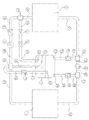
A kind of heat pipe hot pump hybrid system, mainly by condenser, evaporimeter, compressor, choke valve, fluid reservoir, circulating pump, return liquid device, magnetic valve, check valve one, check valve two, check valve three check valves four, wireway, catheter and circuit controling element and constitute; These two heat exchangers of said condenser and evaporimeter mainly are to realize transporting of energy; The output of said check valve one is positioned at the top of fluid reservoir liquid refrigerant liquid level; The input of said check valve two is positioned at the bottom of fluid reservoir liquid refrigerant liquid level; Compressor, condenser, check valve one, fluid reservoir, check valve two, choke valve, evaporimeter are linked in sequence according to above-listed through connecting pipeline like this, have formed a heat pump cycle loop; On said check valve three, fluid reservoir and check valve four formed loops parallel connections and the compressor, and the input of the output of check valve three and check valve four is positioned at the top of fluid reservoir liquid refrigerant liquid level; Connect with check valve two and the choke valve output of institute's structure branch road of said circulating pump, magnetic valve and the output that returns the branch road that the liquid device series connection constituted is connected in the evaporimeter catheter through three-way pipe one; The output of said time liquid device is positioned at the bottom of fluid reservoir liquid refrigerant liquid level, and the input pipe of its output and check valve one, condenser catheter and circulating pump liquid suction pipe are connected in four-way pipe; Circulating pump, magnetic valve, evaporimeter, check valve three, liquid storage filling, check valve four and condenser are linked in sequence according to above-listed through connecting pipeline like this; Formed a heat pipe main circulation loop; Organic assembling through circulating pump, magnetic valve, evaporimeter, check valve three, liquid storage filling and time liquid device; Form independently working solution circulation, i.e. time liquid closed circuit in the heat pipe circulation; When system worked with the heat pump cycle mode, compressor was opened, and check valve one is in conducting state with check valve two, the while circulation pump, and magnetic valve, check valve three and check valve are everywhere in cut-off state; When system works with the heat pump cycle mode; Circulating pump is opened, and magnetic valve, check valve three, check valve four and time liquid device are in conducting state, and compressor cuts out; Check valve one is in cut-off state with check valve two, and above-mentioned two kinds of circulations can be carried out switch operating according to environment and demand.
The above returns liquid device can be the adjustability valve of controllable flow amount, can be the vertical catheter in a certain size cross section, also can be a hole for back flow.
The above returns liquid device can be the adjustability valve of a controllable flow amount; This valve can be a manually-operated gate; It can be the fluid level control valve door; Mainly be the flow that is used for controlling the adjustability valve of liquid refrigeration working medium process controllable flow amount in the fluid reservoir, its flow has the size of its valve to control, and makes the liquid circulation of returning in the heat pipe circulation that a stable liquid closed circuit arranged.
The above returns liquid device can be the vertical catheter in a certain size cross section; This vertical catheter requires straight as far as possible, and highest point can not exceed the height of liquid storage tank level on the whole pipe vertical direction, and requires the top of fluid reservoir at four-way pipe; Make both have certain altitude poor; So that the liquid storage pot liquid is delivered to evaporimeter because the gravity effect is back to four-way pipe through this vertical catheter through delivery pump, the length that this vertical catheter should select fluid reservoir to be complementary to the distance of four-way pipe; Its flow velocity has the cross section of its inlet to control, and makes the liquid circulation of returning in the heat pipe circulation that a stable liquid closed circuit arranged.
The above returns liquid device can be a hole for back flow; Two kinds of connected modes are arranged like this: a kind of is to make check valve one place branch road and time liquid device place branch road be combined into a branch road; New branch road has check valve one and hole for back flow to be in series; It all is in the fluid reservoir, and hole for back flow is on the input pipe duct wall of check valve one between check valve one and the fluid reservoir inwall, and it is under the interior liquid refrigeration medium level of fluid reservoir; Another kind is that a part of pipeline of requirement circulating pump liquid suction pipe and condenser catheter passes fluid reservoir and check valve one place branch road is connected in three-way pipe four; Hole for back flow is positioned at correct position on the tube wall of circulating pump liquid suction pipe; And the pipeline of circulating pump liquid suction pipe is in liquid storage tank level bottom; As close as possible fluid reservoir bottom, its position; So that the liquid refrigerant that stores in the fluid reservoir circulates because the effect of gravity and pressure is delivered to evaporimeter through hole for back flow through circulating pump, and the output of check valve one all is in the top of liquid refrigeration medium level in the fluid reservoir; The pore size of hole for back flow is suitable, makes the liquid circulation of returning in the heat pipe circulation that a stable liquid closed circuit arranged.
It is the high pressure resistant airtight container that an outer surface is provided with thermal insulation layer that the above liquid storage is irritated, and the function of fluid reservoir is to realize the gas-liquid separation and storage working media of periodic duty medium; The fluid reservoir volume size should be complementary with the volume of evaporimeter and condenser; The mode of fluid reservoir realization gas-liquid separation can be selected simple gravity settling separation, also can filter screen or baffle plate be set at the refrigeration working medium input of fluid reservoir, to realize that silk screen separates or baffling separates.
The above magnetic valve mainly is in compressor operating, to be in closed condition, stops the liquid storage pot liquid directly to get into evaporimeter through circulating pump place branch road; Said choke valve can be thermal expansion valve or electric expansion valve; Said circulating pump should be selected the positive displacement gas-liquid two-phase flow circulating pump that can carry gas and liquid simultaneously for use; Can select gear pump, lobe pump, screw pump, rotopiston pump, reciprocating piston pump; Gaseous refrigerant and liquid refrigerant can be passed through simultaneously, and can realize the regulating system heat output through regulating pump flow.
The above circuit control section is being controlled the circuit logic computing and the equipment run switch of whole device, can realize the automation start and stop as required.
The present invention compared with prior art; Separate heat pipe technology and steam compression type refrigeration technology are merged, have complementary advantages, make full use of the power-saving technology of natural cooling source each other, when indoor required design temperature is lower than outdoor temperature, carry out radiating and cooling, when indoor required design temperature is higher than outdoor temperature, circulate and carry out radiating and cooling through heat pipe through heat pump cycle; For throughout the year; Have that to exceed time of 2/3rds be that outdoor temperature is lower than indoor required design temperature, under the heat pipe energy-saving pattern, the highly energy-consuming compressor need not to start like this; Only with the heat pipe energy-saving module and the blower fan that start low power consuming, energy consumption is extremely low; Under refrigeration mode; Because the advantage of two kinds of Refrigeration Technique plyability designs; Make refrigeration efficiency than being superior to general air-conditioning, energy-saving effect is remarkable, and this heat pipe hot pump hybrid system can be applied to the heat radiation temperature control in fields such as base station, machine room and large electric appliances equipment.
Description of drawings
Fig. 1 is the embodiment structural representation of heat pipe hot pump hybrid system.
Fig. 2 is the simple structure sketch map of regulatable time liquid choke valve for time liquid device of this system.
Fig. 3 is a simple structure sketch map that the vertical catheter of a uniform section is arranged for time liquid device of this system.
Fig. 4 is the simple structure sketch map one of a hole for back flow for time liquid device of this system.
Fig. 5 is the simple structure sketch map two of a hole for back flow for time liquid device of this system.
Among the figure: (1) condenser; (2) evaporimeter; (3) fluid reservoir; (4) choke valve; (5) compressor; (6) circulating pump; (7) check valve one; (8) check valve two; (9) check valve three; (10) check valve four; (11) magnetic valve; (12) return liquid device; (13) adjustability valve; (14) vertical catheter; (15) hole for back flow; (16) four-way pipe; (17) three-way pipe one; (18) three-way pipe two; (19) three-way pipe three; (20) output of check valve one; (21) return the output of liquid device; (22) output of check valve two; (23) output of check valve three; (24) input of check valve four; (25) condenser catheter; (26) input pipe of check valve one; (27) efferent duct of check valve one; (28) input pipe of check valve two; (29) efferent duct of choke valve; (30) evaporimeter catheter; (31) evaporimeter wireway; (32) condenser wireway; (33) efferent duct of check valve three; (34) input pipe of check valve four; (35) circulating pump liquid suction pipe; (36) electronic valve efferent duct; (37) input pipe of check valve three; (38) efferent duct of check valve four; (39) compressor inleting pipe; (40) compressor escape pipe, (41) three-way pipe four.
The specific embodiment:
A kind of heat pipe hot pump hybrid system shown in Figure 1 comprises condenser (1), evaporimeter (2), fluid reservoir (3), choke valve (4), compressor (5), circulating pump (6), check valve one (7), check valve two (8), check valve three (9), check valve four (10), magnetic valve (11), returns liquid device (12), adjustability valve (13), the vertically input pipe (34), circulating pump liquid suction pipe (35), electronic valve efferent duct (36), the input pipe (37) of check valve three, efferent duct (38), compressor inleting pipe (39), compressor escape pipe (40), three-way pipe four (41) and the circuit controling element of check valve four of efferent duct (33), the check valve four of efferent duct (29), evaporimeter catheter (30), evaporimeter wireway (31), condenser wireway (32), the check valve three of input pipe (28), the choke valve of efferent duct (27), the check valve two of input pipe (26), the check valve one of input (24), condenser catheter (25), the check valve one of output (23), the check valve four of output (22), the check valve three of output (20), the output (21) that returns liquid device, the check valve two of catheter (14), hole for back flow (15), four-way pipe (16), three-way pipe one (17), three-way pipe two (18), three-way pipe three (19), check valve one; Said compressor (5), three-way pipe three (19), condenser (1), check valve one (7), fluid reservoir (3), check valve two (8), choke valve (4), three-way pipe one (17), evaporimeter (2) and three-way pipe two (18) are linked in sequence according to above-listed through connecting pipeline, have formed a heat pump cycle loop; On said check valve three (9), fluid reservoir (3) and check valve four (10) formed loops parallel connections and the compressor (5), and the input (24) of output of check valve three (23) and check valve four is positioned at the top of fluid reservoir (3) liquid refrigerant liquid level; Said circulating pump (6), magnetic valve (11) and the output of time liquid device (12) series arm and the output of check valve two (8) and choke valve (4) series arm are connected in evaporimeter catheter (30) through three-way pipe one (17); The output (21) of said time liquid device (12) is positioned at the bottom of fluid reservoir (3) liquid refrigerant liquid level, and the input pipe (26) of its output and check valve one, condenser catheter (25) and circulating pump liquid suction pipe (35) are connected in four-way pipe (16); Circulating pump (6), magnetic valve (11), three-way pipe one (17), evaporimeter (2), three-way pipe two (18), check valve three (9), liquid storage filling (3), check valve four (10), three-way pipe three (19), condenser (1) and four-way pipe (16) are linked in sequence according to above-listed through connecting pipeline like this; Formed a heat pipe main circulation loop; Irritate the organic assembling of (3), time liquid device (12) and four-way pipe (16) through circulating pump (6), magnetic valve (11), three-way pipe one (17), evaporimeter (2), three-way pipe two (18), check valve three (9), liquid storage; Form independently working solution circulation, i.e. time liquid closed circuit in the heat pipe circulation; When system works with heat pump; When system works with the heat pump cycle mode; Circulating pump (6) is opened, and magnetic valve (11), check valve three (9), check valve four (10) and time liquid device (12) are in conducting state, and compressor (5) cuts out; Check valve one (7) and check valve two (8) are in cut-off state, and above-mentioned two kinds of circulations can be carried out switch operating according to environment and demand.
Embodiment one:
A kind of heat pipe hot pump hybrid system as shown in Figure 2, used time liquid device (12) are a regulatable time liquid choke valve (13), and its concrete operation principle is following:
When using heat pump cycle mode mode of operation; Compressor (5) is opened; Check valve one (7) and check valve two (8) are in conducting state; Circulating pump (6) cuts out simultaneously; Magnetic valve (11), check valve three (9) and check valve four (10) are in cut-off state, and compressor (5) is from the inner gaseous working medium that extracts of evaporimeter (2), become high-temperature high-pressure state and carry to condenser (1) through compressor (5) gaseous refrigerant; High temperature and high pressure gaseous refrigerant gets in the condenser (1) through three-way pipe three (19) and condenser wireway (32); High temperature and high pressure gaseous refrigerant dispels the heat in condenser (1) then, portion gas liquefaction, and the gas-liquid two-phase cold-producing medium gets into liquid storage through condenser catheter (25) and irritates (3) under the promotion of high-pressure gaseous refrigerant; Gas-liquid refrigeration intermediate medium separates in fluid reservoir according to physical property separately, and the output (22) of high-pressure liquid intermediate medium through check valve two enters into evaporimeter (2) through check valve two (8), choke valve (4), three-way pipe one (17) and evaporimeter catheter (30) successively and circulate next time.
When using the heat-pipe refrigerating mode of operation; Circulating pump (6) is opened; Magnetic valve (11), check valve three (9), check valve four (10) and regulatable time liquid choke valve (13) are in conducting state, and compressor (5) cuts out, and check valve one (7) and check valve two (8) are in cut-off state; Condenser (1) contacts with low-temperature heat source; Gaseous working medium receives the cooling of low-temperature heat source and is condensed into liquid in condenser (1), and emits heat, and the liquid-working-medium that condensation forms is under the drive of delivery pump (6); They enter into evaporimeter (2) from condenser (1); Evaporimeter (2) contacts with high temperature heat source, and liquid working media receives the heating of high temperature heat source and is evaporated to gas in evaporimeter (2), and absorbs heat; The gas that evaporation forms does not have evaporated liquid intermediate medium mutual mixing in flow at high speed to form the gas-liquid two-phase flow body with part; They flow out through check valve three (9) from evaporimeter (2) and get into the fluid reservoir (3), and the middle working media basis of gas-liquid two-phase flow physical property is separately separated in fluid reservoir, and the gaseous state intermediate medium gets into check valve four (10) through interface (24); Circulate in condenser (1) through three-way pipe three (19) and condenser wireway (32) next time; From interface (21) output, the liquid intermediate medium of output and converge from the liquid intermediate medium that condenser (1) comes out and to enter into evaporimeter (2) through circulating pump (6) is simultaneously so just formed a kind of cyclic process of novel energy-conserving heat pipe to liquid intermediate medium through regulatable time liquid choke valve (13).
This like this heat pipe hot pump hybrid system can be according to the difference of indoor required design temperature and outdoor temperature; Optionally (it can be controlled fully automatically; Also can be through controlling to adjust duty manually) run on heat pump refrigerating mode of operation or heat-pipe refrigerating mode of operation, guaranteeing that the prerequisite that room temperature lowering requires is issued to energy-saving run; When higher or indoor load is excessive when outdoor temperature; Heat pipe hot pump hybrid system operating heat pump refrigeration work pattern; Operation principle is identical with general frequency conversion or non-frequency air-conditioning, and indoor heat is dissipated to the exterior space through vapor-compression refrigerant cycle, reaches the cooling cooling effect of the interior space; When outdoor temperature is lower than the indoor temperature certain value; Compressor cuts out; Unit gets into the heat-pipe refrigerating mode of operation automatically, brings to condensation heat release in the condenser to gaseous refrigerant through the heat pipe energy-saving module, becomes condensate liquid at last; Condensate liquid flow to evaporimeter again and absorbs heat under the effect of heat pipe energy-saving module, whole system through the heat pipe energy-saving module with indoor heat to outdoor transmission.
Embodiment two:
A kind of heat pipe hot pump hybrid system as shown in Figure 3; Used time liquid device (12) is for there being the vertical catheter (14) of a uniform section; Control the flow of the liquid refrigerant of backflow through its cross section; This apparatus system is when operating heat pump endless form mode of operation and heat pipe endless form mode of operation, and the startup of miscellaneous part is identical with embodiment one with operation.
Embodiment three:
Like Fig. 4 and a kind of heat pipe hot pump hybrid system shown in Figure 5; Used time liquid device (12) is a promising hole for back flow (15); Control the flow of the liquid refrigerant of backflow through its pore size; This apparatus system is when operating heat pump endless form mode of operation and heat pipe endless form mode of operation, and the startup of miscellaneous part is identical with embodiment one with operation.
Claims (9)
1. heat pipe hot pump hybrid system; Comprise condenser (1), evaporimeter (2), compressor (5), choke valve (4), fluid reservoir (3), wireway, catheter and circuit controling element; It is characterized in that, also comprise circulating pump (6), return liquid device (12), magnetic valve (11), check valve one (7), check valve two (8), check valve three (9) and check valve four (10); These two heat exchangers of said condenser (1) and evaporimeter (2) mainly are to realize transporting of energy; The output of said check valve one (20) is positioned at the top of fluid reservoir (3) liquid refrigerant liquid level; The input of said check valve two (22) is positioned at the bottom of fluid reservoir (3) liquid refrigerant liquid level; Compressor (5), condenser (1), check valve one (7), fluid reservoir (3), check valve two (8), choke valve (4), evaporimeter (2) are linked in sequence according to above-listed through connecting pipeline like this, have formed a heat pump cycle loop; Said check valve three (9), fluid reservoir (3) and check valve four (10) formed loops are parallelly connected with compressor (5), and the input (24) of output of check valve three (23) and check valve four is positioned at the top of fluid reservoir (3) liquid refrigerant liquid level; Said circulating pump (6), magnetic valve (11) and the output of time liquid device (12) series arm and the output of check valve two (8) and choke valve (4) series arm are connected in evaporimeter catheter (30) through three-way pipe one (17); The output (21) of said time liquid device (12) is positioned at the bottom of fluid reservoir (3) liquid refrigerant liquid level, and the input pipe (26) of its output and check valve one, condenser catheter (25) and circulating pump liquid suction pipe (35) are connected in four-way pipe (16); Circulating pump (6), magnetic valve (11), evaporimeter (2), check valve three (9), liquid storage filling (3), check valve four (10) and condenser (1) are linked in sequence according to above-listed through connecting pipeline like this; Formed a heat pipe main circulation loop; Irritate the organic assembling of (3) and time liquid device (12) through circulating pump (6), magnetic valve (11), evaporimeter (2), check valve three (9), liquid storage; Form independently working solution circulation, i.e. time liquid closed circuit in the heat pipe circulation; When system works with the heat pump cycle mode; Compressor (5) is opened; Check valve one (7) and check valve two (8) are in conducting state, and circulating pump (6) cuts out simultaneously, and magnetic valve (11), check valve three (9) and check valve four (10) are in cut-off state; When system works with the heat pipe endless form; Circulating pump (6) is opened; Magnetic valve (11), check valve three (9), check valve four (10) and time liquid device (12) are in conducting state; Compressor (5) cuts out, and check valve one (7) and check valve two (8) are in cut-off state, and above-mentioned two kinds of circulations can be carried out switch operating according to environment and demand.
2. a kind of heat pipe hot pump hybrid system according to claim 1; It is characterized in that; Said time liquid device (12) can be the adjustability valve (13) of controllable flow amount, can be the vertical catheter (14) in a certain size cross section, also can be a hole for back flow (15).
3. a kind of heat pipe hot pump hybrid system according to claim 2; It is characterized in that; Said time liquid device (12) can be the adjustability valve (13) of a controllable flow amount; This valve can be a manually-operated gate, can be the fluid level control valve door, mainly is to be used for controlling the flow of the interior liquid refrigeration working medium of fluid reservoir (3) through the adjustability valve (13) of controllable flow amount; Its flow has the size of its valve to control, and makes the liquid circulation of returning in the heat pipe circulation that a stable liquid closed circuit arranged.
4. a kind of heat pipe hot pump hybrid system according to claim 2; It is characterized in that; Said time liquid device (12) can be the vertical catheter (14) in a certain size cross section; This vertical catheter (14) requires straight as far as possible, and highest point can not exceed the height of the interior liquid level of fluid reservoir (3) on the whole pipe vertical direction, and requires the top of fluid reservoir (3) in four-way pipe (16); Make both have certain altitude poor; So that interior the liquid of fluid reservoir (3) is back to four-way pipe (16) through this vertical catheter (14) owing to the gravity effect, delivers to evaporimeter (2) through delivery pump (3), the length that this vertical catheter (14) should select fluid reservoir (3) to be complementary to the distance of four-way pipe (16); Its flow velocity is controlled by the cross section of its inlet, makes the liquid circulation of returning in the heat pipe circulation that a stable liquid closed circuit arranged.
5. a kind of heat pipe hot pump hybrid system according to claim 2; It is characterized in that; Said time liquid device (12) can be a hole for back flow (15); Two kinds of connected modes are arranged like this: a kind of is to make check valve one (7) place branch road and time liquid device (12) place branch road be combined into a branch road, and new branch road has check valve one (7) and hole for back flow (15) to be in series, and it all is in the fluid reservoir; Hole for back flow (15) is positioned on input pipe (26) duct wall of check valve one between check valve one (7) and fluid reservoir (3) inwall, and it is under the interior liquid refrigeration medium level of fluid reservoir (3); Another kind is that a part of pipeline of requirement circulating pump liquid suction pipe (35) and condenser catheter (25) passes fluid reservoir (3) and check valve one (7) place branch road is connected in three-way pipe four (41); Hole for back flow (15) is positioned at correct position on the tube wall of circulating pump liquid suction pipe (35); And the liquid level bottom of the pipeline of circulating pump liquid suction pipe (35) liquid refrigeration working medium in fluid reservoir (3); The as close as possible fluid reservoir in its position (3) bottom; So that the liquid refrigerant that stores in the fluid reservoir (3) is because the effect of gravity and pressure is delivered to evaporimeter (2) through hole for back flow (15) through circulating pump (6); Circulate; The output of check valve one (20) all is in the top of liquid refrigeration medium level in the fluid reservoir, and the pore size of hole for back flow (15) is suitable, makes the liquid circulation of returning in the heat pipe circulation that a stable liquid closed circuit arranged.
6. a kind of heat pipe hot pump hybrid system according to claim 1; It is characterized in that; It is the high pressure resistant airtight container that an outer surface is provided with thermal insulation layer that said liquid storage is irritated (3), and the function of fluid reservoir (3) is to realize the gas-liquid separation and storage working media of periodic duty medium; Fluid reservoir (3) volume size should be complementary with the volume of evaporimeter (2) and condenser (1); The mode of fluid reservoir (3) realization gas-liquid separation can be selected simple gravity settling separation, also can filter screen or baffle plate be set at the refrigeration working medium input of fluid reservoir (3), to realize that silk screen separates or baffling separates.
7. a kind of heat pipe hot pump hybrid system according to claim 1; It is characterized in that; Said circulating pump (6) should be selected the positive displacement gas-liquid two-phase flow circulating pump that can carry gas and liquid simultaneously for use; Can select gear pump, lobe pump, screw pump, rotopiston pump, reciprocating piston pump, gaseous refrigerant and liquid refrigerant can be passed through simultaneously, and can realize the regulating system heat output through regulating pump flow.
8. a kind of heat pipe hot pump hybrid system according to claim 1; It is characterized in that; Said magnetic valve (11) mainly is in compressor (5) work, to be in closed condition, stops the interior liquid of fluid reservoir (3) directly to get into evaporimeter (2) through circulating pump (6) place branch road; Said choke valve (4) can be thermal expansion valve or electric expansion valve.
9. a kind of heat pipe hot pump hybrid system according to claim 1, its characteristic also is: said circuit control section is being controlled the circuit logic computing and the equipment run switch of whole device, can realize the automation start and stop as required.
Priority Applications (1)
| Application Number | Priority Date | Filing Date | Title |
|---|---|---|---|
| CN201210269424.9A CN102759159B (en) | 2012-08-01 | 2012-08-01 | A kind of heat pipe hot pump composite system |
Applications Claiming Priority (1)
| Application Number | Priority Date | Filing Date | Title |
|---|---|---|---|
| CN201210269424.9A CN102759159B (en) | 2012-08-01 | 2012-08-01 | A kind of heat pipe hot pump composite system |
Publications (2)
| Publication Number | Publication Date |
|---|---|
| CN102759159A true CN102759159A (en) | 2012-10-31 |
| CN102759159B CN102759159B (en) | 2016-06-01 |
Family
ID=47053715
Family Applications (1)
| Application Number | Title | Priority Date | Filing Date |
|---|---|---|---|
| CN201210269424.9A Active CN102759159B (en) | 2012-08-01 | 2012-08-01 | A kind of heat pipe hot pump composite system |
Country Status (1)
| Country | Link |
|---|---|
| CN (1) | CN102759159B (en) |
Cited By (6)
| Publication number | Priority date | Publication date | Assignee | Title |
|---|---|---|---|---|
| CN102878620A (en) * | 2012-11-02 | 2013-01-16 | 北京德能恒信科技有限公司 | Two-phase flow refrigeration system |
| CN102927646A (en) * | 2012-11-26 | 2013-02-13 | 北京德能恒信科技有限公司 | Computer room air conditioner |
| CN103683050A (en) * | 2013-12-04 | 2014-03-26 | 国网上海市电力公司 | Sound-insulation cooling device for indoor transformer/electric reactor |
| CN107314579A (en) * | 2017-06-23 | 2017-11-03 | 青岛海信日立空调系统有限公司 | The control method of gas-liquid separator, air conditioner and air conditioner |
| CN108397845A (en) * | 2017-02-07 | 2018-08-14 | 施耐德电气It公司 | The cooling system of pressure drop with reduction |
| CN111928704A (en) * | 2020-08-06 | 2020-11-13 | 中国航空工业集团公司沈阳飞机设计研究所 | Two-phase fluid composite heat exchange system |
Citations (3)
| Publication number | Priority date | Publication date | Assignee | Title |
|---|---|---|---|---|
| JP2000337663A (en) * | 1999-05-26 | 2000-12-08 | Sanyo Electric Co Ltd | Air conditioner |
| CN102331055A (en) * | 2011-10-24 | 2012-01-25 | 北京德能恒信科技有限公司 | Cold and warm heat pipe and heat pump air conditioning |
| CN202675513U (en) * | 2012-08-01 | 2013-01-16 | 北京德能恒信科技有限公司 | Heat pipe and heat pump combined system |
-
2012
- 2012-08-01 CN CN201210269424.9A patent/CN102759159B/en active Active
Patent Citations (3)
| Publication number | Priority date | Publication date | Assignee | Title |
|---|---|---|---|---|
| JP2000337663A (en) * | 1999-05-26 | 2000-12-08 | Sanyo Electric Co Ltd | Air conditioner |
| CN102331055A (en) * | 2011-10-24 | 2012-01-25 | 北京德能恒信科技有限公司 | Cold and warm heat pipe and heat pump air conditioning |
| CN202675513U (en) * | 2012-08-01 | 2013-01-16 | 北京德能恒信科技有限公司 | Heat pipe and heat pump combined system |
Cited By (11)
| Publication number | Priority date | Publication date | Assignee | Title |
|---|---|---|---|---|
| CN102878620A (en) * | 2012-11-02 | 2013-01-16 | 北京德能恒信科技有限公司 | Two-phase flow refrigeration system |
| CN102878620B (en) * | 2012-11-02 | 2016-09-21 | 北京丰联奥睿科技有限公司 | A kind of two-phase flow refrigeration system |
| CN102927646A (en) * | 2012-11-26 | 2013-02-13 | 北京德能恒信科技有限公司 | Computer room air conditioner |
| CN102927646B (en) * | 2012-11-26 | 2016-06-01 | 北京德能恒信科技有限公司 | A kind of air conditioner in machine room |
| CN103683050A (en) * | 2013-12-04 | 2014-03-26 | 国网上海市电力公司 | Sound-insulation cooling device for indoor transformer/electric reactor |
| CN103683050B (en) * | 2013-12-04 | 2017-03-22 | 国网上海市电力公司 | Sound-insulation cooling device for indoor transformer/electric reactor |
| CN108397845A (en) * | 2017-02-07 | 2018-08-14 | 施耐德电气It公司 | The cooling system of pressure drop with reduction |
| CN108397845B (en) * | 2017-02-07 | 2021-10-22 | 尤尼弗莱尔股份有限公司 | Cooling system with reduced pressure drop |
| CN107314579A (en) * | 2017-06-23 | 2017-11-03 | 青岛海信日立空调系统有限公司 | The control method of gas-liquid separator, air conditioner and air conditioner |
| CN111928704A (en) * | 2020-08-06 | 2020-11-13 | 中国航空工业集团公司沈阳飞机设计研究所 | Two-phase fluid composite heat exchange system |
| CN111928704B (en) * | 2020-08-06 | 2022-03-29 | 中国航空工业集团公司沈阳飞机设计研究所 | Two-phase fluid composite heat exchange system |
Also Published As
| Publication number | Publication date |
|---|---|
| CN102759159B (en) | 2016-06-01 |
Similar Documents
| Publication | Publication Date | Title |
|---|---|---|
| CN102788392B (en) | A kind of heat pipe hot pump hybrid system | |
| CN102767880B (en) | A kind of heat pipe hot pump hybrid system | |
| CN102798184B (en) | A kind of heat pipe hot pump hybrid system | |
| CN203848433U (en) | Heat pipe and heat pump dual-mode air conditioner with evaporative condenser | |
| CN103307683B (en) | A kind of heat pipe air conditioner all-in-one | |
| CN203364317U (en) | Heat pipe and air conditioner integrated machine | |
| CN202204076U (en) | Heat recovery air conditioning cabinet applicable to animal room | |
| CN204006452U (en) | A kind of condensation heat recovery type frequency conversion type constant-temperature constant-humidity air-conditioner | |
| CN102759159A (en) | Heat pipe and heat pump composite system | |
| CN111442575A (en) | Adjustable refrigerating device and refrigerating adjusting method | |
| CN102829522A (en) | Heat pipe and heat pump compound system | |
| CN208720535U (en) | A kind of manifold type high temperature space energy heat-pump hot-water unit | |
| CN203442994U (en) | Heat pipe air conditioner all-in-one machine | |
| CN105627624A (en) | Separate heating process of heat pump and hot water heating combined system | |
| CN201476397U (en) | Temperature-adjusting dehumidifier of water source heat pump | |
| CN202709360U (en) | Heat pipe and heat pump combined system | |
| CN102927646A (en) | Computer room air conditioner | |
| CN203413743U (en) | Heat pipe and heat pump composite system | |
| CN202675513U (en) | Heat pipe and heat pump combined system | |
| CN101592416B (en) | Cooling and heating system with cooling-heating source complementing loop | |
| CN103017410A (en) | Heating-cooling type heat pipe and heat pump combined circulating system | |
| CN203132025U (en) | Base station room air conditioner | |
| CN211476359U (en) | Constant temperature and humidity air conditioning unit | |
| CN202675517U (en) | Heat pipe and heat pump combined system | |
| CN203132020U (en) | Machine room base station air conditioner energy-saving device |
Legal Events
| Date | Code | Title | Description |
|---|---|---|---|
| C06 | Publication | ||
| PB01 | Publication | ||
| C10 | Entry into substantive examination | ||
| SE01 | Entry into force of request for substantive examination | ||
| C14 | Grant of patent or utility model | ||
| GR01 | Patent grant | ||
| C56 | Change in the name or address of the patentee | ||
| CP01 | Change in the name or title of a patent holder |
Address after: 100041 Beijing, Badachu hi tech park, West Wells Road, building 9415, room 3, No., room 3 Patentee after: Beijing Science and Technology Co., Ltd. Germany To Hanson Address before: 100041 Beijing, Badachu hi tech park, West Wells Road, building 9415, room 3, No., room 3 Patentee before: Beijing Science and Technology Co., Ltd. Germany to Hanson |