CN102695068A - Imaging device, synchronization control method, reproduction device, and stereoscopic video imaging system - Google Patents
Imaging device, synchronization control method, reproduction device, and stereoscopic video imaging system Download PDFInfo
- Publication number
- CN102695068A CN102695068A CN2012100791583A CN201210079158A CN102695068A CN 102695068 A CN102695068 A CN 102695068A CN 2012100791583 A CN2012100791583 A CN 2012100791583A CN 201210079158 A CN201210079158 A CN 201210079158A CN 102695068 A CN102695068 A CN 102695068A
- Authority
- CN
- China
- Prior art keywords
- synchronizing signal
- vertical synchronizing
- processed frame
- frame
- camera
- Prior art date
- Legal status (The legal status is an assumption and is not a legal conclusion. Google has not performed a legal analysis and makes no representation as to the accuracy of the status listed.)
- Pending
Links
Images


Classifications
-
- H—ELECTRICITY
- H04—ELECTRIC COMMUNICATION TECHNIQUE
- H04N—PICTORIAL COMMUNICATION, e.g. TELEVISION
- H04N13/00—Stereoscopic video systems; Multi-view video systems; Details thereof
- H04N13/20—Image signal generators
- H04N13/296—Synchronisation thereof; Control thereof
-
- H—ELECTRICITY
- H04—ELECTRIC COMMUNICATION TECHNIQUE
- H04N—PICTORIAL COMMUNICATION, e.g. TELEVISION
- H04N13/00—Stereoscopic video systems; Multi-view video systems; Details thereof
- H04N13/20—Image signal generators
- H04N13/204—Image signal generators using stereoscopic image cameras
-
- H—ELECTRICITY
- H04—ELECTRIC COMMUNICATION TECHNIQUE
- H04N—PICTORIAL COMMUNICATION, e.g. TELEVISION
- H04N13/00—Stereoscopic video systems; Multi-view video systems; Details thereof
- H04N13/20—Image signal generators
- H04N13/204—Image signal generators using stereoscopic image cameras
- H04N13/239—Image signal generators using stereoscopic image cameras using two 2D image sensors having a relative position equal to or related to the interocular distance
Abstract
The invention discloses an imaging device, a synchronization control method, a reproduction device and a stereoscopic video imaging system. The imaging device includes an operation unit that instructs an operation by operation input, an imaging control unit that controls an operation of an imaging unit having a first imaging element, a counting unit that counts the number of generation times of the vertical synchronization signal, and a control unit that calculates the number of generation times of the vertical synchronization signal inserted between second processing frames based on a difference value between the number of generation times of the vertical synchronization signal generated by a second imaging element of the other imaging device and inserted between the second processing frames and the number of generation times of the vertical synchronization signal inserted between first processing frames, so as to notify the other imaging device of timing to start an instructed operation and an instruction, and perform the notified operation after elapse of a predetermined period.
Description
Technical field
The disclosure relates to and being preferably applied to from for example generated imaging device, synchronisation control means, reproducer and the three-dimensional video-frequency imaging system of the situation of stereoscopic video images (3D video image) by the captured video images of two cameras.
Background technology
In correlation technique; There is following technology; Through utilizing video image by the captured same subject of two cameras to generate the stereoscopic video images (3D video image) that can be watched by the user three-dimensionally, these two cameras are by to arrange corresponding to user's the left eye and the mode of right eye parallax.In order to take stereoscopic video images, the beginning of video record or stop or the beginning of rabbit or stop (followingly only being called " beginning of processing or stop ") and carried out by mode with the operation of synchronous two cameras.
The open No.2006-163640 of japanese unexamined patent discloses this technology: a plurality of video tape recorders are connected in series to video camera, and first connector that recording signal is sent to is connected by two-way with second connector that returning of state confirmation signal is sent to.
Summary of the invention
Incidentally, the three-dimensional video-frequency imaging system of correlation technique does not have linking functions, through this linking functions, and two mutual operations of camera control.Therefore, even if the user about two magazine executable operations inputs because not the matching of the timing of operation input, two cameras also are difficult to carry out the beginning of handling simultaneously or stop.Here; If (promptly by the beginning of the performed processing of two cameras or the timing that stops; Captured by camera separately or reproduce Video signal processing frame) incomplete coupling, then reproduced with the three-dimensional video image of watching in produce jamais vu, it generates faulty video image.Therefore, must wait the beginning of independent matching treatment frame or stop timing through the timing code that utilization is attached to by two clip files separately that camera generated.
In addition, the open No.2006-163640 of above-mentioned japanese unexamined patent discloses continuous execution and has handled the technology that makes a plurality of video tape recorders confirm state simultaneously.But this technology only is used in the following situation: video tape recorder is by operation together each other.Therefore, be used so that take in the situation of stereoscopic video images at two cameras, it is regarded as recording of control of video image strictly or is reproduced.
Hope the timing of matching treatment exactly when utilizing two imaging devices to handle stereoscopic video images.
A kind of imaging device according to embodiment of the present disclosure comes guiding operation through the operation input; And through control the operation of image-generating unit through the incident light of the object of camera lens incident; This image-generating unit has first image-forming component, and this first image-forming component is exported the vision signal in first processed frame to each vertical synchronizing signal that is inserted between first processed frame.In addition, this imaging device is to being counted by the generation number of times of the vertical synchronizing signal that image-forming component generated, as the frame number of first processed frame.In addition, this imaging device obtain from other imaging devices notices of being connected to imaging device through the control line that transmits control signal, by second image-forming component generation number of times that generate and that be inserted into the vertical synchronizing signal between second processed frame of these other imaging devices.Here, this imaging device is based on the generation number of times that is inserted into the vertical synchronizing signal between second processed frame and be inserted into the generation number of times that difference between the generation number of times of the vertical synchronizing signal between first processed frame is calculated the vertical synchronizing signal that is inserted between second processed frame.Then; Based on the generation number of times that is inserted into the vertical synchronizing signal between second processed frame, this imaging device notifies these other imaging devices importing given instruction through the timing of the operation that begins after the scheduled time slot to be instructed and by operation to these other imaging devices.In addition, this imaging device was lighted through carrying out the operation of being notified after the scheduled time slot in the time that is performed from the operation input.
Therefore, can be after through the scheduled time slot between two imaging devices, timing place of the operation of being instructed in beginning provides instruction through the operation input.
According to embodiment of the present disclosure; First imaging device is imported given instruction to other imaging device notices in the timing of the operation that begins through other imaging devices after the scheduled time slot to be instructed and by operation; And, light through carrying out the operation of being notified after the scheduled time slot in the time that is performed from the operation input.Therefore,, can carry out simultaneously by the indicated operation of operation input when when utilizing two imaging devices to handle stereoscopic video images, and, but the beginning of enhancement process or the accuracy that stops.
Description of drawings
Fig. 1 shows the block diagram according to the exterior arrangement example of the three-dimensional video-frequency imaging system of embodiment of the present disclosure;
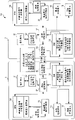
Fig. 2 shows the block diagram according to the internal configurations example of the three-dimensional video-frequency imaging system of embodiment of the present disclosure;
Fig. 3 A to Fig. 3 C shows the sequential chart of example of the timing of the mutual control and treatment operation of first camera and second camera in an embodiment of the present invention;
Fig. 4 shows the flow chart of the processing example of first camera among the embodiment of the present disclosure;
Fig. 5 shows the flow chart by the processing example at the interface of the performed camera control unit of synchronous control unit among the embodiment of the present disclosure;
Fig. 6 shows the flow chart by the processing example at the interface of the performed user interface control unit of synchronous control unit among the embodiment of the present disclosure;
Fig. 7 shows the flow chart by the processing example at the interface of the performed transmission of synchronous control unit/reception control unit among the embodiment of the present disclosure.
Embodiment
Embodiment of the present disclosure (below be called embodiment) below will be described.To provide description with following order.
1. embodiment (the Synchronization Control of two cameras: the example of three-dimensional video-frequency imaging system)
2. revise
1. embodiment
[the Synchronization Control examples of two cameras]
With reference to accompanying drawing embodiment of the present disclosure is described at present.In this embodiment, the three-dimensional video-frequency imaging system 10 of taking stereoscopic video images with the mode of the beginning of the processing of synchronous two cameras (imaging device) or the timing that stops is used as example (below, be called " this example ") and describes.Three-dimensional video-frequency imaging system 10 is used to control beginning or the synchronous synchronisation control means that stops of the processing of two cameras.
Fig. 1 shows the exterior arrangement example of three-dimensional video-frequency imaging system 10.
Three-dimensional video-frequency imaging system 10 comprises that as first camera 1 of imaging device and second camera 2 said imaging device frame with equal number in a second is taken the two-dimensional video image with identical picture size.First camera 1 and second camera 2 are provided with the general line terminal.First camera 1 and second camera 2 can send/receive and be used for controlling recording or the synchronous control signal of reproduction processes with the mutual video image of synchronization frame unit; Through train line 3 synchronous control signal is put into communication packet simultaneously, this train line 3 is connected to line terminals and can carries out serial communication.
First camera 1 and second camera 2 comprise operating unit 11, and through this operating unit 11, user guided each unit is about the operation of operation input.As operating unit 11, for example use the console switch (record button, reproduce button etc.) on camera body, unshowned remote controller, button push, toggle switch (toggle switch), contact panel display etc.
Three-dimensional video-frequency imaging system 10 also comprises signal conversion equipment 4, and this signal conversion equipment 4 will convert stereo video signals to from the vision signal of first camera 1 and 2 inputs of second camera.Signal conversion equipment 4 outputs to display device 5 with two dimension or 3 D video signal, and this display device 5 can two dimension ground or three-dimensional ground display video image.
First camera 1 and second camera 2 are placed in the mounting table (RIG) 6 in the stereoscopic video images shooting.Generally speaking, the zoom magnification ratio (zoom magnification) of first camera 1 and second camera 2 is set to not scalable, and first camera 1 and second camera 2 are arranged, and makes interval between its lens corresponding to human eye.Can visually be identified as the solid object of nature by the user through being combined in the stereoscopic video images that two-dimensional video image obtained captured in this state.
But; When first camera 1 with big shell (casing) and second camera 2 by side by side in the horizontal direction the time; Object is used than the bigger parallax in the interval of human eye and is taken, and it causes the uncomfortable feeling of the stereoscopic video images that the user visually discerns about the user.Therefore, first camera 1 and second camera 2 are disposed on the mounting table 6 that is provided with half mirror 7.Here, the image light that first camera 1 is disposed in object is via half mirror 7 and by on the position of directly incident, and second camera 2 is disposed in the image light of object by half mirror 7 reflection and by on the position of incident.Therefore, first camera 1 and second camera 2 are arranged, and the light shaft positive cross of the camera lens of the win camera 1 and second camera 2 is intersected.
Fig. 2 shows the internal configurations example of three-dimensional video-frequency imaging system 10.
First camera 1 and second camera 2 have mutually the same functional block.Therefore, in the following description, the internal configurations example of first camera 1 has been described.In the following description, in order to describe the processing of first camera 1, first camera 1 can be called as " equipment of itself ", and second camera 2 can be called as " other equipment ".
First camera 1 comprises from the user interface control unit 12 of operating unit 11 reception operation inputs, the camera control unit 13 of control imaging operation, and RAM 14.When operating unit 11 was contact panel display, user interface control unit 12 is display graphical user interfaces (GUI) on screen.First camera 1 also comprises playback control unit 15; These playback control unit 15 controls are to being recorded in the reproduction of the video image in the unshowned recording elements; This first camera 1 also comprises recording control unit 16; When video image was recorded in the recording elements, this recording control unit 16 was carried out control.First camera 1 also comprises synchronous control unit 17, and the operation of this synchronous control unit 17 controls second camera 2 makes imaging operation and to the reproduction of video image or record by synchronously to carry out with the processing of second camera 2.First camera 1 also comprises RAM 18 and the transmission/reception control unit 19 of storing various Counter Values, and this transmission/reception control unit 19 is controlled the transmission/reception to communication packet through train line 3.
User interface control unit 12 is carried out with not shown and be set to the processing that the performed operation input of button of operating unit 11 receives; The processing of execution to receiving from the operation input that unshowned remote controller received, and carry out the processing that the performed operation input of using such as WLAN of remote control is received.User interface control unit 12 is handled by the given instruction of operation input etc., and this operation input is from the input of the graphic user interface such as touch pad, and, carry out and handle on contact panel display etc., to show various menus and message.In addition, user interface control unit 12 is imported given instruction to synchronous control unit 17 notices by the operation that receives from operating unit 11.
The vertical synchronizing signal Counter Value that the vertical synchronizing signal counter 20 that the generation number of times of the vertical synchronizing signal of every frame of being obtained from camera control unit 13 is counted will be used as the frame number of processed frame is written among RAM 14.Vertical synchronizing signal counter 20 is used as counting unit, and this counting unit will be the frame number of first processed frame by the generation time counting number of the vertical synchronizing signal that image-forming component generated.The number of the vertical synchronizing signal that 20 pairs of image-forming components of being controlled from camera control unit 13 imaging of vertical synchronizing signal counter interrupt is counted, and RAM 14 stores the number of the vertical synchronizing signal that is write by vertical synchronizing signal counter 20.
The timing that synchronous control unit 17 is tentatively generated the vertical synchronizing signal of first processed frame is complementary with the timing that the vertical synchronizing signal of second processed frame is generated.Here, 2 pairs in second camera is inserted into the generation number of times of the vertical synchronizing signal between second processed frame and counts, as the frame number of second processed frame.Whether at this moment, when second image-forming component generated vertical synchronizing signal, synchronous control unit 17 judged to a plurality of frame periods, utilize the difference of frame number of the frame number that frame number calculated and first processed frame of second processed frame that is received from second camera 2 constant.When this difference to a plurality of frame period when being constant, the frame number of the timing that synchronous control unit 17 begins to operate as second camera 2 to second camera, 2 notices, this frame number obtains through the frame number that is calculated that is added to second processed frame a plurality of frame period.Through this control, the timing of the operation that first camera, 1 control, second camera 2 begins to be indicated.Here, import " indicated operation " by the operation of operating unit 11 and comprise that imaging begins or stops or rabbit begins or stops, and first processed frame comprises into picture frame or rendering frame with second processed frame.
Therefore, the difference between the Counter Value of the vertical synchronizing signal of synchronous control unit 17 acquisition first cameras 1 and second camera 2, and, carry out control with second camera 2 to the synchronization timing of operational order.Though the detailed process to synchronous control unit 17 will be described after a while,, handle all by synchronous control unit 17 execution in all shown in the flow chart of Fig. 4 to Fig. 7.
In addition, synchronous control unit 17 has the interface that is used for about camera control unit 13 transmission/reception data, and carries out the transmission/reception control unit interface processing about transmission/reception control unit 19.This processing is carried out about the module at the interface of transmission/reception control unit 19 by operation.RAM18 storage by first camera 1 and second camera 2 each other the vertical synchronizing signals of receptions Counter Value, by the performed operational order of first camera 1, as the Counter Value of the vertical synchronizing signal of the triggering of the beginning of operational order etc.
Transmission/reception control unit 19 is carried out transmission to communication packet and is received the processing etc. of handling, communication packet being sent to the processing of second camera 2, comes the communication equipment of processing that converts communications divides into groups, controlling packet vinculum terminal etc. according to specified communication protocol.The beginning of the synchronous control unit 17 generation number of times of vertical synchronizing signal Counter Value (in this example based on) computing frame regularly, this processed frame is performed with the beginning of Synchronous Processing or the timing that stops.Then, the transmission/reception control unit 19 request control data that will be used to instruct the operation that second camera 2 carries out carrying out with handle frame number and send to second camera 2.
The 1 preliminary genlock of passing through to carry out about second camera 2 (genlock) of first camera comes the processed frame of synchronous first camera 1 and the processed frame of second camera 2.This is executed in the generation regularly of vertical synchronizing signal synchronously, and synchronous control unit 17 is controlled, and makes the amount of not matching of synchronization timing in the time of about delegation.In this example, carried out control, wherein based on master and servant's relation; First camera 1 is set to main equipment, and second camera 2 is set to subset, and; The synchronous Be Controlled of the processed frame of second camera 2 comes to be complementary with the processed frame of first camera 1 with the instruction according to first camera 1.
As stated, through genlock, the beginning of the processed frame of first camera 1 regularly with the beginning of the processed frame of second camera 2 synchronised regularly.Then, the difference of first camera 1 and second camera, 2 detection of vertical synchronizing signals, this vertical synchronizing signal are counted by operating in separately magazine software program respectively.Here, vertical synchronizing signal is generated by timing place that begins at processed frame, and the synchronous control unit 17 of first camera 1 is calculated the frame number of the processed frame of second camera, 2 operations based on this difference.Therefore; Be used to carry out the beginning of processing or stop and during when first camera 1 as main equipment receives by the given operational order of user's operation input; The operation of first camera, 1 control, second camera 2 is so that second camera 2 is to carry out the beginning of processing with first camera, 1 synchronous mode or to stop.Therefore, first camera 1 is carried out Synchronization Control, and through this Synchronization Control, the processing of second camera 2 regularly quilt is complementary with processing every frame regularly as first camera 1.
The communication packet of between camera, being transmitted is made up of following: represent " K field (4 byte) " of command type, " L field (4 byte) " of representative data length, and " V field (maximum 64 bytes) " of representative data content.In the K field, stored and be used to instruct data in synchronization, and, in the V field, stored representative to the beginning of the processing of equipment of itself or the data content that stops.For example, when representative was included in the K field to the data of the notice of vertical synchronizing signal Counter Value, the vertical synchronizing signal Counter Value of equipment of itself was included in the V field.In addition, when the information of the form of notifying clip files is included in the K field, represent the information of picture size, frame per second and the bit rate of video image to be included in the V field.
Through send via train line 3/received communication divides into groups, first camera of being controlled by software program 1 and second camera 2 can be directed against every frame and carry out processing with the mode of mutually synchronization mutually.Therefore, enabled synchronous execution to the processing of the beginning of recording of the video image of taking in identical timing place of every frame or shut-down operation and to the processing of reproducing or stop the content of same format in every frame.
Here, first camera 1 and second camera 2 also are used as the reproducer that reproduces video image with the method for synchronization.In this situation, second camera 2 is used as other reproducers that connect through train line 3.At this moment, will to be inserted into the generation time counting number of the vertical synchronizing signal between first frame of the vision signal of being reproduced by the playback control unit 15 of second camera 2 be the frame number of second processed frame of second camera 2 to vertical synchronizing signal counter 20.Then, the generation of the vertical synchronizing signal that has obtained to be notified number by second camera 2, this vertical synchronizing signal is generated and is inserted between second processed frame by the image-forming component of second camera 2.Based on above-mentioned generation number be inserted into the difference between the generation number of times of the vertical synchronizing signal between first processed frame, the generation number of times that is inserted into the vertical synchronizing signal between second processed frame is calculated.Then, based on the generation number of times that is inserted into the vertical synchronizing signal between second processed frame, second camera 2 is by the following timing of notice with by the given instruction of operation input, and second camera 2 regularly is in through after the scheduled time slot at this and begins indicated operation.At this moment, first camera 1 regularly and by operation is imported given instruction to the beginning of second camera, 2 notifying operations, and, after the scheduled time slot of the time point that is performed through the operation input of associating, carry out the operation of being notified.Comprise the beginning of imaging or stop by the indicated operation of the operation of operating unit 11 input, and first and second processed frames comprise into picture frame or rendering frame.
The sequential chart of the example that the operation timing that Fig. 3 A to Fig. 3 C shows second camera 2 is controlled by first camera 1.
Fig. 3 A shows the example of the sequential chart in the synchronous state of not controlling first camera 1 and second camera 2.
First camera 1 utilizes the vertical synchronizing signal that generates in different timings place respectively with second camera 2, so that the coupling beginning is regularly, and, be based on the processed frame that sets in the period between the adjacent vertical synchronizing signal, the processing of carrying out imaging or reproducing.First camera 1 operates in the processed frame of identical frame per second with second camera 2.But very difficult accurately match user is operated the timing of operating unit 11 to power on of camera separately, and therefore, the timing that processed frame begins to locate differs from one another.Therefore, if as correlation technique, the image of object is being taken in following state: the beginning of processed frame regularly differs from one another, and then the beginning of matching treatment or the operation that stops must be carried out after image taking.
Fig. 3 B shows the example of process based on the processed frame of second camera 2 of the genlock of the processed frame of first camera 1.
In this example, carry out control as follows: the beginning timing of the processed frame of second camera 2 regularly is complementary with the beginning of the processed frame of first camera 1, and the vertical synchronizing signal of first camera 1 is used as the beginning synchronizing signal regularly that is used for the matching treatment frame.Through the synchronous control signal that sends from first camera 1 via train line 3, be performed about the genlock of the processed frame of second camera 2.Here, first camera 1 has identical configuration with second camera 2, and therefore the processed frame of second camera 2 can be used as synchronizing signal, to carry out the genlock to the processed frame of first camera 1.
The processing that beginning with the processed frame of first camera 1 and second camera 2 regularly is complementary has been described here.
At first,, vertical synchronizing signal regularly generated the vertical synchronizing signal Counter Value that first camera 1 is counted to second camera, 2 notices via train line 3 in case being used as first of processed frame.This vertical synchronizing signal Counter Value is used as the Counter Value of processed frame.
Through similar mode,, vertical synchronizing signal regularly generates the vertical synchronizing signal Counter Value that second camera 2 is counted to first camera, 1 notice via train line 3 in case being used as first of processed frame.In Fig. 3 B, for ease, the vertical synchronizing signal Counter Value of first camera 1 is counted as n, n+1 ..., and the vertical synchronizing signal Counter Value of second camera 2 is counted as m, m+1 ....
First camera 1 and second camera 2 be the vertical synchronizing signal Counter Value of notice in the period of a frame each other.This operates on some frames and carries out.Then, the synchronous control unit 17 calculated difference Δs of first camera 1, this difference DELTA obtains through the vertical synchronizing signal Counter Value that from the vertical synchronizing signal Counter Value of first camera 1, deducts to second camera 2 that some frames obtained.In this example, obtain a value, and when the difference DELTA of on some frames, calculating was mutually the same continuously value, this difference DELTA was used as mean value and obtains through difference DELTA=n-m.
As (m+3) frame of second camera 2, have following situation here: the Counter Value of (m+3) frame is not notified in next (n+4) frame by notice in correspondence (n+3) frame of first camera 1.For example, have following situation: first camera 1 is difficult to the frame number to first processed frame of second camera, 2 notices in the period of first processed frame, or in the period of first processed frame, receives the frame number of second processed frame from second camera 2.In this situation, the frame number of frame first processed frame in period of the synchronous control unit 17 of first camera 1 after second camera 2 is notified first processing.Replacedly, first camera 1 receives the frame number of second processed frame from second camera 2.Therefore, first camera 1 and second camera 2 can be each other the frame number of notifier processes frame safely.
As shown in Fig. 3 B; Be less than when synchronous control unit 17 and obtaining second difference DELTA in the number of times of pre-determined number '; This second difference DELTA ' when being different from the difference DELTA that in pre-determined number or the number of times more than pre-determined number, is obtained, synchronous control unit 17 abandons second difference DELTA '.In the example of Fig. 3 B, second difference DELTA ' pass through Δ '=(n+4)-(m+3)=n-m+1 obtains.Therefore, second difference DELTA of unexpected deviation average ' be dropped.Therefore, how the synchronous control unit 17 of first camera 1 processed frame that can calculate second camera 2 based on difference DELTA departs from the processed frame of first camera 1.
Fig. 3 C shows that in fact first camera 1 and second camera 2 carry out the beginning of handling or the example of the timing when stopping.
As shown in Fig. 3 B, the synchronous control unit 17 of first camera 1 is calculated difference DELTA.Here, in Fig. 3 C, for convenience, the processed frame of first camera 1 is counted as x, x+1 ..., and the processed frame of second camera 2 is counted as y, y+1 ...
When the beginning of handling or stop by when (x+5) frame is carried out, synchronous control unit 17 instructs for second camera 2, on the Counter Value of (y+5) frame, to override the Counter Value of (x+5-Δ) frame.At this moment, synchronous control unit 17 Counter Values with (y+5) frame of second camera 2 are rewritten in the Counter Value of (x+5-Δ) frame.Therefore, first camera 1 and second camera 2 are being carried out the beginning of handling by identical timing place as the Counter Value of same number of frames shown in the note of the asterisk among Fig. 3 C or are being stopped.
Now, with reference to Fig. 4 to Fig. 7, the processing example of synchronous control unit 17 is described as the processing example of three-dimensional video-frequency imaging system 10 especially., in this example, synchronous control unit 17 has been described here, because first camera 1 is set to main equipment.But, even if be used as in the situation of main equipment at second camera 2, second camera 2 also can carry out with below the identical processing of described synchronous control unit 17.
Fig. 4 shows the processing example of first camera 1.
At first, when train line 3 was connected to the line terminals of first camera 1 and second camera 2, the Synchronization Control ray mode was opened (step S1) by the operation input of operating unit 11, and this operation input is carried out through unshowned menu screen by the user.When the Synchronization Control ray mode is unlocked; The imaging processing of video image or the reproduction processes of video image can be in a synchronous manner, between first camera 1 and second camera 2, be performed in the processed frame of each camera in master and servant's relation; Wherein, First camera 1 is set to main equipment, and second camera 2 is set to subset.On the other hand, when the Synchronization Control ray mode is turned off, each camera independent operation, and therefore, be independent of each other mutually.
Next, first camera 1 and second camera 2 are notified vertical synchronizing signal Counter Value (step S2) through serial communication via train line 3 each other.Next, the synchronous control unit 17 of first camera 1 detects the vertical synchronizing signal Counter Value of equipment of itself and the vertical synchronizing signal Counter Value that receives from second camera 2 poor.At this moment, if obtain identical difference continuously to N frame (being 5 frames in this example), then first camera 1 is confirmed this difference (step S3).
Then, first camera 1 receive by operation signal make to beginning of handling or the instruction that stops, this operation signal is generated in response to carrying out the input operation on operating unit 11.In response to this instruction, the Counter Value of the processed frame of the some frames after first camera 1 is specified according to the call duration time that is used to instruct second camera 2 is so that send to second camera 2 (step S4) with operational order.Execution after the timing diagram shown in Fig. 3 C shows 5 frames.
Then, first camera 1 and second camera 2 are to carry out mutually the same operation (step S5) with the synchronous mode of timing of the vertical synchronizing signal that generates in identical timing place.Therefore, only through operation first camera 1, the user can make second camera 2 carry out identical operations.
Next, through describing with reference to Fig. 5 to Fig. 7 by the performed processing example of synchronous control unit 17 about the interface of each unit.In the following description, synchronous control unit 17 execution are called as " processing at interface " about the processing of the I/O of the data of each control unit.
Fig. 5 shows the processing example by the interface of the performed camera control unit 13 of synchronous control unit 17.
At first, synchronous control unit 17 waits are by the interruption (step S11) of the vertical synchronizing signal that image-forming component generated.When the interruption of vertical synchronizing signal took place, vertical synchronizing signal counter 20 was written to the vertical synchronizing signal Counter Value among the RAM 14.Then, synchronous control unit 17 obtains vertical synchronizing signal Counter Value (step S12) from RAM 14.
After first camera 1 powered on, the vertical synchronizing signal Counter Value counted up to " 255 " from " 0 " through vertical synchronizing signal counter 20 with being repeated.Here, the vertical synchronizing signal Counter Value at the time point place that vertical synchronizing signal counter 20 begins to count has random value.In addition, if between first camera 1 and second camera 2 be stable synchronously, then difference DELTA is a fixed value, and, all calculated at the absolute value of the vertical synchronizing signal Counter Value at the time point place that begins to operate at every turn.Therefore, the vertical synchronizing signal Counter Value need not to be reset and is " 0 ".
Next, synchronous control unit 17 will send to second camera 2 (step S13) from the vertical synchronizing signal that RAM 14 reads.Sending the processing of vertical synchronizing signal Counter Value is carried out by the module at the interface of handling camera control unit 13.Then, synchronous control unit 17 requests are from the transmission of transmission/reception control unit 19, and therefore, transmission process is performed.
Next, synchronous control unit 17 judges whether the vertical synchronizing signal Counter Value of equipment of itself equals the vertical synchronizing signal Counter Value (step S14) at the time point place that second camera 2 begins to operate.When the vertical synchronizing signal Counter Value is equal to each other, synchronous control unit 17 carry out about playback control unit 15 or recording control unit 16 to video image in line or record command (step S15).When the vertical synchronizing signal Counter Value differed from one another, synchronous control unit 17 was not carried out any processing, but end process.
Fig. 6 shows by the performed processing example to the interface of user interface control unit 12 of synchronous control unit 17.
At first, synchronous control unit 17 is waited for the operational order of being made by operation signal (step S21), and this operation signal is generated in response to user's operation input.But it is uncertain when in processed frame, providing from user's operational order.Therefore; Synchronous control unit 17 is carried out genlock in response to operational order; Make vertical synchronizing signal be created on simultaneously between first camera 1 and second camera 2; It can be from the operation that begins to be indicated of processed frame, the timing that the beginning of this processed frame generated for vertical synchronizing signal.
In addition, through operation signal being sent to the operational order of second camera, 2, the first cameras, 1 notice by operating unit 11 operation inputs.Here, the timing when operation signal arrives second camera 2 is uncertain, and therefore, when operation is carried out by reality is unclear.Therefore, first camera 1 and second camera 2 tentatively obtain difference DELTA from the vertical synchronizing signal Counter Value of being counted by vertical synchronizing signal counter 20 separately.Through this difference, according to difference DELTA, the vertical synchronization that can begin operation place at first camera 1 and second camera 2 in a synchronous manner receives the back Counter Value to be calculated.
Then, based on the difference DELTA of being judged by the vertical synchronizing signal Counter Value that is received from second camera 2, the synchronous control unit 17 of first camera 1 calculates vertical synchronizing signal Counter Value (step S22) at the time point place that second camera 2 begins to operate.In addition, the unit 17 of the Synchronization Control of first camera 1 calculates vertical synchronizing signal Counter Value (step S23) with the mode that the processing with step S22 walks abreast at the time point place that is beginning to operate at first camera 1.
The dotted line representative that is branched off into step S23 on next step of step S21 performed processing when first camera 1 is set to subset.Be provided with this processing, because depend on that the operational order that receives from operating unit 11 is the Counter Value of equipment of itself or the Counter Value of other equipment, the processing that will carry out is different.Next, synchronous control unit 17 will be used for the operation signal of executable operations instruction and send to second camera 2 (step S24) at the time point place vertical synchronizing signal Counter Value that operation is activated, and processing finishes.
Fig. 7 shows the processing example by the interface of the performed transmission/reception control unit 19 of synchronous control unit 17.
At first, the synchronous control unit 17 of first camera 1 is waited for the reception (step S31) of vertical synchronizing signal Counter Value, and this vertical synchronizing signal Counter Value is received from transmission/reception control unit 19.If do not receive the vertical synchronizing signal Counter Value from second camera 2, then processing finishes.
On the other hand, when transmission/reception control unit 19 when second camera 2 receives vertical synchronizing signal Counter Values (step S32), transmission/reception control unit 19 is written to the vertical synchronizing signal Counter Value among the RAM 18.Next, synchronous control unit 17 obtains vertical synchronizing signal Counter Value (step S33) from RAM 18.Then, synchronous control unit 17 calculates the vertical synchronizing signal Counter Value of the equipment of itself of reading from RAM 14 and the difference DELTA (step S34) of the vertical synchronizing signal Counter Value of second camera 2 read from RAM 18.
Then, synchronous control unit 17 judge difference DELTA enable difference judge Counter Value increase value or corresponding to second difference DELTA ' exceptional value (step S37).When difference DELTA is exceptional value, do not carry out processing.On the other hand, when difference DELTA is to enable difference when judging the value of increase of Counter Value, in the subsequent treatment of step S38, carry out with before the difference of time override the processing of the difference of being judged.
In this example, difference judges that Counter Value is used, so that judge the difference DELTA of vertical synchronizing signal Counter Value.For example, shown in above-mentioned Fig. 3 C, in the situation that the communication packet of sending through train line 3 is postponed, the time was poor before the difference of this moment possibly be different from.In order to be discarded in this situation as the difference DELTA that difference obtained at this moment; This control is performed; Make difference at this moment in delegation, have N time (being 5 times in this example) not have in the situation of equal values with the difference of time point before, difference at this moment is not counted as correct difference DELTA.
Here, when difference DELTA changed, the difference DELTA that synchronous control unit 17 once will change was written among the RAM 14, as " time is poor " before.Next, when obtaining identical difference DELTA, synchronous control unit 17 judges that with the difference among the RAM 14 Counter Value increases by 1.In addition, when the difference of this moment when the difference of time has equal values continuously before, synchronous control unit 17 continues all to increase at every turn and differs from the judgement Counter Value.Therefore, difference at this moment and before the difference of time on the N frame, have in the situation of equal values, obtained (step S38) by represented " difference of judgement " of above-mentioned difference DELTA.In addition, difference at this moment and before the difference of time in delegation, have in the situation that has equal values for N time, judge that as difference " N " value of Counter Value is covered to difference and judges in the Counter Value (step S39), and, the processing end.Here, the difference of each this moment when the difference of time has equal values before, the value of increase " N " just.
When the difference of this moment in the processing of step S35 when the difference of time differs from one another before, with the difference of this moment be updated/written among the RAM 14 before poor (the step S40) of time, and difference judges that Counter Value is by with default value " 1 " rewriting (step S41).Next, step S31 is repeated to the processing of step S39, so that whether the represented value of difference when obtaining thus is the poor Δ of judging.
, have following situation here: first camera 1 is set to subset, and second camera 2 is set to main equipment.In this situation, the transmission of first camera 1/reception control unit 19 receives operation signals from second camera 2, and the synchronous control unit 17 of first camera 1 interrupts by the indicated operation (step S42) of second camera 2.In addition, the vertical synchronizing signal Counter Value (step S43) at the time point place of the transmission of first camera 1/reception control unit 19 when second camera 2 receives operation, and, this vertical synchronizing signal Counter Value is written among the RAM18 of first camera 1.Then; Based on the difference of judging; The vertical synchronizing signal Counter Value (step S44) at the time point place the when synchronous control unit 17 of first camera 1 begins with the operation of calculating equipment of itself with the parallel mode of the processing of not enough S43, and, the operation of being controlled by second camera 2 carried out.
According to the three-dimensional video-frequency imaging system 10 of the foregoing description, in the situation that the generation of vertical synchronizing signal is regularly mated each other, through first camera 1 and second camera 2 that utilization has master and servant's relation, the difference DELTA of vertical synchronizing signal Counter Value is obtained.Then, according to this difference DELTA, the beginning of processing or stop to be judged, and therefore, the beginning of processing or stop when arriving this frame number, to be synchronized execution by the frame number that reality is carried out.At this moment, when the user only carries out about for example as the operation input of the operating unit 11 of first camera 1 of main equipment the time, second camera 2 is carried out and first camera, 1 identical operations.Therefore, with the beginning of processed frame regularly the processing of two synchronous cameras beginning or stop and can being accurately controlled.
In addition, the beginning of processed frame timing quilt regularly is complementary with the generation of the vertical synchronizing signal of vision signal, makes that the operation of dealing with frame separately can accurately be mated.Therefore, after theme is formed images, needn't carry out the operation of adjustment processed frame, make edit operation become more effective.In addition, in the process of reproducing video image, can reproduce operation, make and to eliminate because the uncomfortable feeling that unmatched processed frame caused about stereo-picture so that two cameras are carried out in a synchronous manner.
In addition, difference DELTA obtains at the fixed time or on the longer period, makes that value has high confidence level.Therefore, through utilizing difference DELTA, matching treatment frame easily.In addition, the user needn't consider the beginning of matching treatment or stop, because only through the operation of first camera 1, second camera 2 is automatically to operate with first camera, 1 synchronous mode.
In addition, second difference DELTA that obtains as exceptional value ' be dropped, make second difference DELTA ' does not influence Synchronization Control.Put from this, can strengthen the confidence level of the Synchronization Control of first camera 1 and second camera 2.
2. revise
In the above-described embodiments, describe first camera 1 and second camera 2 and be arranged this example in vertical direction.But, the size of the shell through first camera 1 that reduces and second camera 2, first camera 1 and second camera 2 can be by side by side in the horizontal direction.
In addition, in example, described train line 3 and be used as the wire cable that is connected to transmission/reception control unit 19.But through utilizing the adapter compatible mutually with wireless communication standard as transmission/reception control unit 19, communication packet can wirelessly be sent.
Above-mentioned a series of processing can be by hardware or software executing.When a series of processing during by software executing, processing can be carried out by computer, and wherein, the program of forming software is integrated in the specialized hardware or is used to carry out various functional programs and is mounted.For example, be installed in the general purpose personal computer, can carry out processing through the program that will form desirable software.
In addition, the recording medium of program code that has wherein write down the software of the function that is used for realizing the foregoing description can be set at system or device.In addition, obviously, through reading and carry out the program code that is stored in the recording medium by the computer (or the control appliance such as CPU) of system or device, function is implemented.
In this situation, be used to provide the example of the recording medium of program code to comprise flexible dish, hard disk, CD, magneto optical disk, CD-ROM, CD-R, disk, Nonvolatile memory card and ROM.
Through carrying out the program code of being read by computer, the function of the foregoing description is implemented.In addition, based on the instruction of program code, operate in OS operating part or whole actual treatment on computer etc.Also comprise the situation that the function of the foregoing description is implemented through processing.
Should be noted that embodiment of the present disclosure is not limited to the foregoing description, and variations and modifications appear in the scope of the present disclosure.
The disclosure can have following configuration.
(1) a kind of imaging device comprises:
Operating unit, this operating unit are configured to come guiding operation through the operation input;
The imaging control unit; This imaging control unit is configured to control through the incident light of the object of process camera lens incident the operation of image-generating unit; This image-generating unit has first image-forming component, and this first image-forming component is exported the vision signal in first processed frame to each vertical synchronizing signal that is inserted between first processed frame;
Counting unit, this counting unit are configured to the generation number of times of the vertical synchronizing signal that is generated by said first image-forming component is counted; And
Control unit; This control unit based on other imaging devices notices that connect from the control line through transmission of control signals, by being included in that second image-forming component said other imaging devices is generated and being inserted into the generation number of times of the vertical synchronizing signal between second processed frame and the difference that is inserted between the generation number of times of the vertical synchronizing signal between said first processed frame is calculated the generation number of times that is inserted into the vertical synchronizing signal between said second processed frame; So that come to notify said other imaging devices importing given instruction through the timing of the operation that begins after the scheduled time slot to be instructed and by said operation to said other imaging devices based on the generation number of times that is inserted into the vertical synchronizing signal between said second processed frame; And, light the operation of being notified through execution after the said scheduled time slot from the time that said operation input is performed.
(2) according to (1) described imaging device, wherein
Said counting unit is to the generation time counting number of the vertical synchronizing signal that generated by said first image-forming component, as the frame number of said first processed frame, and
Timing that the vertical synchronizing signal of timing that the vertical synchronizing signal of said first processed frame is generated and said second processed frame is generated each other tentatively coupling and said other imaging devices to the generation time situation of counting number that is inserted into the vertical synchronizing signal between said second processed frame as the frame number of said second processed frame under; Said control unit is notified through being added to the frame number that frame number obtained of said second processed frame a plurality of frame period to said other imaging devices; As the timing that said other imaging devices begin to operate, the frame number of said second processed frame is that the difference of frame number of frame number and said first processed frame of said second processed frame that when each said second image-forming component generates vertical synchronizing signal, receives from said other imaging devices calculates when all being constant for a plurality of frame period.
(3) according to (1) or (2) described imaging device, wherein
When said control unit is difficult in the period of said first processed frame to notify the frame number of said first processed frame or be difficult in the period of said first processed frame when said other imaging devices receive the frame number of said second processed frame to said other imaging devices, the frame of said control unit after said first processed frame notified the frame number of said first processed frame or received the frame number of said second processed frame from said other imaging devices to said other imaging devices in the period.
(4) according to any the described imaging device in (1) to (3), wherein
When said control unit obtained the second following difference, said control unit abandons this second difference: said second difference was that in being less than the number of times of pre-determined number, obtain and different with the difference that in pre-determined number or the number of times more than pre-determined number, is obtained.
(5) according to any the described imaging device in (1) to (3); Wherein, The operation of being instructed by the operation of said operating unit input comprise the beginning of imaging and stop in one, and said first processed frame comprises in picture frame and the rendering frame with said second processed frame.
(6) a kind of synchronisation control means comprises:
Come guiding operation through the operation input;
Through control the operation of image-generating unit through the incident light light of the object of camera lens incident; This image-generating unit has first image-forming component, and this first image-forming component is exported the vision signal in first processed frame to each vertical synchronizing signal that is inserted between first processed frame;
Generation number of times to the vertical synchronizing signal that generated by said first image-forming component is counted; And
Based on other imaging devices notices that connect from the control line through transmission of control signals, by being included in that second image-forming component said other imaging devices is generated and being inserted into the generation number of times of the vertical synchronizing signal between second processed frame and the difference that is inserted between the generation number of times of the vertical synchronizing signal between said first processed frame is calculated the generation number of times that is inserted into the vertical synchronizing signal between said second processed frame; So that come to notify said other imaging devices importing given instruction through the timing of the operation that begins after the scheduled time slot to be instructed and by said operation to said other imaging devices based on the generation number of times that is inserted into the vertical synchronizing signal between said second processed frame; And, light the operation of being notified through execution after the said scheduled time slot from the time that said operation input is performed.
(7) a kind of reproducer comprises:
Operating unit, this operating unit are configured to come guiding operation through the operation input;
Counting unit, this counting unit are configured to read and counted by the generation number of times of the vertical synchronizing signal between first processed frame of the vision signal reproduced being inserted into from record cell; And
Control unit; This control unit based on other reproducers notices that connect from the control line through transmission of control signals, by be included in said other reproducers image-forming component generated and be inserted into the generation number of times of the vertical synchronizing signal between second processed frame and the difference that is inserted between the generation number of times of the vertical synchronizing signal between said first processed frame is calculated the generation number of times that is inserted into the vertical synchronizing signal between said second processed frame; So that come to notify said other reproducers importing given instruction through the timing of the operation that begins after the scheduled time slot to be instructed and by said operation to said other reproducers based on the generation number of times that is inserted into the vertical synchronizing signal between said second processed frame; And, light the operation of being notified through execution after the said scheduled time slot from the time that said operation input is performed.
(8) a kind of three-dimensional video-frequency imaging system comprises:
First imaging device; And
Second imaging device; Wherein
Said first imaging device comprises
First operating unit, this first operating unit are configured to come guiding operation through the operation input;
The first imaging control unit; This first imaging control unit is configured to control through the incident light of the object of process camera lens incident the operation of image-generating unit; This image-generating unit has first image-forming component, and this first image-forming component is exported the vision signal in first processed frame to each vertical synchronizing signal that is inserted between first processed frame;
First counting unit, this first counting unit are configured to the generation number of times of the vertical synchronizing signal that is generated by said first image-forming component is counted; And
First control unit; This first control unit based on said second imaging device notice that connects from the control line through transmission of control signals, by being included in that second image-forming component said second imaging device is generated and being inserted into the generation number of times of the vertical synchronizing signal between second processed frame and the difference that is inserted between the generation number of times of the vertical synchronizing signal between said first processed frame is calculated the generation number of times that is inserted into the vertical synchronizing signal between said second processed frame; So that come to notify said second imaging device importing given instruction through the timing of the operation that begins after the scheduled time slot to be instructed and by said operation to said second imaging device based on the generation number of times that is inserted into the vertical synchronizing signal between said second processed frame; And, light the operation of being notified through execution after the said scheduled time slot from the time that said operation input is performed; And
Said second imaging device comprises
The second imaging control unit; This second imaging control unit is configured to control through the incident light of the object of process camera lens incident the operation of second image-generating unit; This second image-generating unit has second image-forming component, and this second image-forming component is exported the vision signal in second processed frame to each vertical synchronizing signal that is inserted between second processed frame;
Second counting unit, this second counting unit are configured to the generation number of times of the vertical synchronizing signal that is generated by said second image-forming component is counted; And
Second control unit; This second control unit is inserted into the generation number of times of the vertical synchronizing signal between said second processed frame to said first imaging device notice; And be based on through the timing of the operation that begins after the scheduled time slot to be instructed and by the given instruction of said operation input; Light through carrying out the operation of being notified after the said scheduled time slot in the time that is performed from said operation input, said timing and said instruction all receive from said first imaging device.
The disclosure comprises and the disclosed relevant subject content of japanese priority patent application JP 2011-066254 of date of filing this patent on the 24th office March in 2011 that its full content is incorporated into this by reference.
Claims (8)
1. imaging device comprises:
Operating unit, this operating unit are configured to come guiding operation through the operation input;
The imaging control unit; This imaging control unit is configured to control through the incident light of the object of process camera lens incident the operation of image-generating unit; This image-generating unit has first image-forming component, and this first image-forming component is exported the vision signal in first processed frame to each vertical synchronizing signal that is inserted between first processed frame;
Counting unit, this counting unit are configured to the generation number of times of the vertical synchronizing signal that is generated by said first image-forming component is counted; And
Control unit; This control unit based on other imaging devices notices that connect from the control line through transmission of control signals, by being included in that second image-forming component said other imaging devices is generated and being inserted into the generation number of times of the vertical synchronizing signal between second processed frame and the difference that is inserted between the generation number of times of the vertical synchronizing signal between said first processed frame is calculated the generation number of times that is inserted into the vertical synchronizing signal between said second processed frame; So that come to notify said other imaging devices importing given instruction through the timing of the operation that begins after the scheduled time slot to be instructed and by said operation to said other imaging devices based on the generation number of times that is inserted into the vertical synchronizing signal between said second processed frame; And, light the operation of being notified through execution after the said scheduled time slot from the time that said operation input is performed.
2. imaging device according to claim 1, wherein
Said counting unit is to the generation time counting number of the vertical synchronizing signal that generated by said first image-forming component, as the frame number of said first processed frame, and
Timing that the vertical synchronizing signal of timing that the vertical synchronizing signal of said first processed frame is generated and said second processed frame is generated each other tentatively coupling and said other imaging devices to the generation time situation of counting number that is inserted into the vertical synchronizing signal between said second processed frame as the frame number of said second processed frame under; Said control unit is notified through being added to the frame number that frame number obtained of said second processed frame a plurality of frame period to said other imaging devices; As the timing that said other imaging devices begin to operate, the frame number of said second processed frame is that the difference of frame number of frame number and said first processed frame of said second processed frame that when each said second image-forming component generates vertical synchronizing signal, receives from said other imaging devices calculates when all being constant for a plurality of frame period.
3. imaging device according to claim 2, wherein
When said control unit is difficult in the period of said first processed frame to notify the frame number of said first processed frame or be difficult in the period of said first processed frame when said other imaging devices receive the frame number of said second processed frame to said other imaging devices, the frame of said control unit after said first processed frame notified the frame number of said first processed frame or received the frame number of said second processed frame from said other imaging devices to said other imaging devices in the period.
4. imaging device according to claim 3, wherein
When said control unit obtained the second following difference, said control unit abandons this second difference: said second difference was that in being less than the number of times of pre-determined number, obtain and different with the difference that in pre-determined number or the number of times more than pre-determined number, is obtained.
5. imaging device according to claim 4; Wherein, The operation of being instructed by the operation of said operating unit input comprise the beginning of imaging and stop in one, and said first processed frame comprises in picture frame and the rendering frame with said second processed frame.
6. synchronisation control means comprises:
Come guiding operation through the operation input;
Through control the operation of image-generating unit through the incident light light of the object of camera lens incident; This image-generating unit has first image-forming component, and this first image-forming component is exported the vision signal in first processed frame to each vertical synchronizing signal that is inserted between first processed frame;
Generation number of times to the vertical synchronizing signal that generated by said first image-forming component is counted; And
Based on other imaging devices notices that connect from the control line through transmission of control signals, by being included in that second image-forming component said other imaging devices is generated and being inserted into the generation number of times of the vertical synchronizing signal between second processed frame and the difference that is inserted between the generation number of times of the vertical synchronizing signal between said first processed frame is calculated the generation number of times that is inserted into the vertical synchronizing signal between said second processed frame; So that come to notify said other imaging devices importing given instruction through the timing of the operation that begins after the scheduled time slot to be instructed and by said operation to said other imaging devices based on the generation number of times that is inserted into the vertical synchronizing signal between said second processed frame; And, light the operation of being notified through execution after the said scheduled time slot from the time that said operation input is performed.
7. reproducer comprises:
Operating unit, this operating unit are configured to come guiding operation through the operation input;
Counting unit, this counting unit are configured to read and counted by the generation number of times of the vertical synchronizing signal between first processed frame of the vision signal reproduced being inserted into from record cell; And
Control unit; This control unit based on other reproducers notices that connect from the control line through transmission of control signals, by be included in said other reproducers image-forming component generated and be inserted into the generation number of times of the vertical synchronizing signal between second processed frame and the difference that is inserted between the generation number of times of the vertical synchronizing signal between said first processed frame is calculated the generation number of times that is inserted into the vertical synchronizing signal between said second processed frame; So that come to notify said other reproducers importing given instruction through the timing of the operation that begins after the scheduled time slot to be instructed and by said operation to said other reproducers based on the generation number of times that is inserted into the vertical synchronizing signal between said second processed frame; And, light the operation of being notified through execution after the said scheduled time slot from the time that said operation input is performed.
8. three-dimensional video-frequency imaging system comprises:
First imaging device; And
Second imaging device; Wherein
Said first imaging device comprises
First operating unit, this first operating unit are configured to come guiding operation through the operation input;
The first imaging control unit; This first imaging control unit is configured to control through the incident light of the object of process camera lens incident the operation of image-generating unit; This image-generating unit has first image-forming component, and this first image-forming component is exported the vision signal in first processed frame to each vertical synchronizing signal that is inserted between first processed frame;
First counting unit, this first counting unit are configured to the generation number of times of the vertical synchronizing signal that is generated by said first image-forming component is counted; And
First control unit; This first control unit based on said second imaging device notice that connects from the control line through transmission of control signals, by being included in that second image-forming component said second imaging device is generated and being inserted into the generation number of times of the vertical synchronizing signal between second processed frame and the difference that is inserted between the generation number of times of the vertical synchronizing signal between said first processed frame is calculated the generation number of times that is inserted into the vertical synchronizing signal between said second processed frame; So that come to notify said second imaging device importing given instruction through the timing of the operation that begins after the scheduled time slot to be instructed and by said operation to said second imaging device based on the generation number of times that is inserted into the vertical synchronizing signal between said second processed frame; And, light the operation of being notified through execution after the said scheduled time slot from the time that said operation input is performed; And
Said second imaging device comprises
The second imaging control unit; This second imaging control unit is configured to control through the incident light of the object of process camera lens incident the operation of second image-generating unit; This second image-generating unit has second image-forming component, and this second image-forming component is exported the vision signal in second processed frame to each vertical synchronizing signal that is inserted between second processed frame;
Second counting unit, this second counting unit are configured to the generation number of times of the vertical synchronizing signal that is generated by said second image-forming component is counted; And
Second control unit; This second control unit is inserted into the generation number of times of the vertical synchronizing signal between said second processed frame to said first imaging device notice; And be based on through the timing of the operation that begins after the scheduled time slot to be instructed and by the given instruction of said operation input; Light through carrying out the operation of being notified after the said scheduled time slot in the time that is performed from said operation input, said timing and said instruction all receive from said first imaging device.
Applications Claiming Priority (2)
| Application Number | Priority Date | Filing Date | Title |
|---|---|---|---|
| JP2011-066254 | 2011-03-24 | ||
| JP2011066254A JP2012204987A (en) | 2011-03-24 | 2011-03-24 | Imaging apparatus, synchronization control method, reproducing apparatus, and stereoscopic video imaging system |
Publications (1)
| Publication Number | Publication Date |
|---|---|
| CN102695068A true CN102695068A (en) | 2012-09-26 |
Family
ID=46860330
Family Applications (1)
| Application Number | Title | Priority Date | Filing Date |
|---|---|---|---|
| CN2012100791583A Pending CN102695068A (en) | 2011-03-24 | 2012-03-16 | Imaging device, synchronization control method, reproduction device, and stereoscopic video imaging system |
Country Status (3)
| Country | Link |
|---|---|
| US (1) | US20120242805A1 (en) |
| JP (1) | JP2012204987A (en) |
| CN (1) | CN102695068A (en) |
Cited By (4)
| Publication number | Priority date | Publication date | Assignee | Title |
|---|---|---|---|---|
| CN104113748A (en) * | 2014-07-17 | 2014-10-22 | 冯侃 | 3D shooting system and implementation method |
| CN106162141A (en) * | 2015-03-13 | 2016-11-23 | 钰立微电子股份有限公司 | Image processing apparatus and image processing method |
| CN111150397A (en) * | 2018-11-07 | 2020-05-15 | 西门子医疗有限公司 | Method for creating an image of an examination object, medical imaging system and use thereof |
| CN112153354A (en) * | 2020-08-13 | 2020-12-29 | 中国科学院西安光学精密机械研究所 | Frame synchronization image shooting method |
Families Citing this family (5)
| Publication number | Priority date | Publication date | Assignee | Title |
|---|---|---|---|---|
| JP5709545B2 (en) * | 2011-01-18 | 2015-04-30 | キヤノン株式会社 | Imaging device |
| JP5821300B2 (en) * | 2011-06-07 | 2015-11-24 | ソニー株式会社 | Imaging apparatus and imaging method |
| JP5927795B2 (en) * | 2011-07-22 | 2016-06-01 | ソニー株式会社 | Stereoscopic imaging system, recording control method, stereoscopic video playback system, and playback control method |
| WO2015136798A1 (en) * | 2014-03-13 | 2015-09-17 | ソニー株式会社 | Image capture device, image capture system, and method for controlling image capture device |
| JP6075357B2 (en) | 2014-11-19 | 2017-02-08 | カシオ計算機株式会社 | Imaging apparatus, imaging control method, and program |
Family Cites Families (4)
| Publication number | Priority date | Publication date | Assignee | Title |
|---|---|---|---|---|
| JPH03185996A (en) * | 1989-12-14 | 1991-08-13 | Konica Corp | Video camera for stereoscopic video image |
| JP4262019B2 (en) * | 2003-07-08 | 2009-05-13 | 日本放送協会 | Video synchronization method and video synchronization program |
| JP3731589B2 (en) * | 2003-07-18 | 2006-01-05 | ソニー株式会社 | Imaging device and synchronization signal generator |
| JP4851118B2 (en) * | 2005-05-23 | 2012-01-11 | ソニー株式会社 | Imaging system, imaging control device, vertical synchronization method, and program |
-
2011
- 2011-03-24 JP JP2011066254A patent/JP2012204987A/en active Pending
-
2012
- 2012-03-09 US US13/415,995 patent/US20120242805A1/en not_active Abandoned
- 2012-03-16 CN CN2012100791583A patent/CN102695068A/en active Pending
Cited By (9)
| Publication number | Priority date | Publication date | Assignee | Title |
|---|---|---|---|---|
| CN104113748A (en) * | 2014-07-17 | 2014-10-22 | 冯侃 | 3D shooting system and implementation method |
| CN106162141A (en) * | 2015-03-13 | 2016-11-23 | 钰立微电子股份有限公司 | Image processing apparatus and image processing method |
| US10148934B2 (en) | 2015-03-13 | 2018-12-04 | Eys3D Microelectronics, Co. | Image process apparatus and image process method |
| CN106162141B (en) * | 2015-03-13 | 2020-03-10 | 钰立微电子股份有限公司 | Image processing apparatus and image processing method |
| CN111150397A (en) * | 2018-11-07 | 2020-05-15 | 西门子医疗有限公司 | Method for creating an image of an examination object, medical imaging system and use thereof |
| CN111150397B (en) * | 2018-11-07 | 2023-09-08 | 西门子医疗有限公司 | Method for creating an image of an examination object, medical imaging system and use thereof |
| US11881300B2 (en) | 2018-11-07 | 2024-01-23 | Siemens Healthcare Gmbh | Method, system, and medical imaging system for creating an image of an examination object and the use of such images |
| CN112153354A (en) * | 2020-08-13 | 2020-12-29 | 中国科学院西安光学精密机械研究所 | Frame synchronization image shooting method |
| CN112153354B (en) * | 2020-08-13 | 2021-07-27 | 中国科学院西安光学精密机械研究所 | Frame synchronization image shooting method |
Also Published As
| Publication number | Publication date |
|---|---|
| JP2012204987A (en) | 2012-10-22 |
| US20120242805A1 (en) | 2012-09-27 |
Similar Documents
| Publication | Publication Date | Title |
|---|---|---|
| CN102695068A (en) | Imaging device, synchronization control method, reproduction device, and stereoscopic video imaging system | |
| US8937647B2 (en) | Stereoscopic imaging system, recording control method, stereoscopic image reproduction system, and reproduction control method | |
| US10958820B2 (en) | Intelligent interface for interchangeable sensors | |
| CN103024272A (en) | Double camera control device, method and system of mobile terminal and mobile terminal | |
| KR20140039920A (en) | Image data processing method and apparatus, and electronic device including the same | |
| JP2011239379A (en) | Image capturing system, image capturing apparatus, and image capturing method | |
| EP2767886A1 (en) | Electronic equipment and program | |
| JP5970748B2 (en) | Moving image photographing system and synchronization control method | |
| CN102629974B (en) | Image capturing apparatus and its control method | |
| US20120062554A1 (en) | Reproducing apparatus | |
| CN103888646A (en) | Image Pickup Apparatus And Control Method Of Image Pickup Apparatus | |
| JP2009094663A (en) | Imaging apparatus | |
| EP2950518A1 (en) | Electronic device | |
| US20130010133A1 (en) | Control apparatus and method therefor | |
| KR101238965B1 (en) | Camera combined with smart device | |
| US9565386B2 (en) | Image data transmitting apparatus and image data receiving apparatus | |
| JP5657223B2 (en) | Imaging apparatus, image reproduction system, and image reproduction method | |
| JP6911392B2 (en) | Image acquisition device, image acquisition method, program and image acquisition system | |
| JP5587089B2 (en) | Communication apparatus and control method | |
| CN103905698A (en) | Imaging apparatus | |
| JP7001141B2 (en) | Image pickup device, image pickup method, program, and image acquisition system | |
| JP2014160927A (en) | Imaging device | |
| JP2005229538A (en) | Digital camera system | |
| JP2022191143A (en) | Image processing device and image processing method | |
| US20110157384A1 (en) | Stabilizing rod for a video camera stabilizer |
Legal Events
| Date | Code | Title | Description |
|---|---|---|---|
| C06 | Publication | ||
| PB01 | Publication | ||
| SE01 | Entry into force of request for substantive examination | ||
| SE01 | Entry into force of request for substantive examination | ||
| C02 | Deemed withdrawal of patent application after publication (patent law 2001) | ||
| WD01 | Invention patent application deemed withdrawn after publication |
Application publication date: 20120926 |