CN102640373A - Wire separator suitable for use in a cable splice enclosure - Google Patents
Wire separator suitable for use in a cable splice enclosure Download PDFInfo
- Publication number
- CN102640373A CN102640373A CN2010800545817A CN201080054581A CN102640373A CN 102640373 A CN102640373 A CN 102640373A CN 2010800545817 A CN2010800545817 A CN 2010800545817A CN 201080054581 A CN201080054581 A CN 201080054581A CN 102640373 A CN102640373 A CN 102640373A
- Authority
- CN
- China
- Prior art keywords
- core
- separator
- line
- cable
- separating arm
- Prior art date
- Legal status (The legal status is an assumption and is not a legal conclusion. Google has not performed a legal analysis and makes no representation as to the accuracy of the status listed.)
- Pending
Links
Images


Classifications
-
- F—MECHANICAL ENGINEERING; LIGHTING; HEATING; WEAPONS; BLASTING
- F16—ENGINEERING ELEMENTS AND UNITS; GENERAL MEASURES FOR PRODUCING AND MAINTAINING EFFECTIVE FUNCTIONING OF MACHINES OR INSTALLATIONS; THERMAL INSULATION IN GENERAL
- F16L—PIPES; JOINTS OR FITTINGS FOR PIPES; SUPPORTS FOR PIPES, CABLES OR PROTECTIVE TUBING; MEANS FOR THERMAL INSULATION IN GENERAL
- F16L3/00—Supports for pipes, cables or protective tubing, e.g. hangers, holders, clamps, cleats, clips, brackets
-
- H—ELECTRICITY
- H02—GENERATION; CONVERSION OR DISTRIBUTION OF ELECTRIC POWER
- H02G—INSTALLATION OF ELECTRIC CABLES OR LINES, OR OF COMBINED OPTICAL AND ELECTRIC CABLES OR LINES
- H02G15/00—Cable fittings
- H02G15/08—Cable junctions
- H02G15/10—Cable junctions protected by boxes, e.g. by distribution, connection or junction boxes
- H02G15/117—Cable junctions protected by boxes, e.g. by distribution, connection or junction boxes for multiconductor cables
-
- F—MECHANICAL ENGINEERING; LIGHTING; HEATING; WEAPONS; BLASTING
- F16—ENGINEERING ELEMENTS AND UNITS; GENERAL MEASURES FOR PRODUCING AND MAINTAINING EFFECTIVE FUNCTIONING OF MACHINES OR INSTALLATIONS; THERMAL INSULATION IN GENERAL
- F16L—PIPES; JOINTS OR FITTINGS FOR PIPES; SUPPORTS FOR PIPES, CABLES OR PROTECTIVE TUBING; MEANS FOR THERMAL INSULATION IN GENERAL
- F16L9/00—Rigid pipes
- F16L9/18—Double-walled pipes; Multi-channel pipes or pipe assemblies
- F16L9/19—Multi-channel pipes or pipe assemblies
-
- H—ELECTRICITY
- H02—GENERATION; CONVERSION OR DISTRIBUTION OF ELECTRIC POWER
- H02G—INSTALLATION OF ELECTRIC CABLES OR LINES, OR OF COMBINED OPTICAL AND ELECTRIC CABLES OR LINES
- H02G15/00—Cable fittings
- H02G15/08—Cable junctions
- H02G15/10—Cable junctions protected by boxes, e.g. by distribution, connection or junction boxes
- H02G15/113—Boxes split longitudinally in main cable direction
-
- Y—GENERAL TAGGING OF NEW TECHNOLOGICAL DEVELOPMENTS; GENERAL TAGGING OF CROSS-SECTIONAL TECHNOLOGIES SPANNING OVER SEVERAL SECTIONS OF THE IPC; TECHNICAL SUBJECTS COVERED BY FORMER USPC CROSS-REFERENCE ART COLLECTIONS [XRACs] AND DIGESTS
- Y10—TECHNICAL SUBJECTS COVERED BY FORMER USPC
- Y10T—TECHNICAL SUBJECTS COVERED BY FORMER US CLASSIFICATION
- Y10T29/00—Metal working
- Y10T29/49—Method of mechanical manufacture
- Y10T29/49002—Electrical device making
- Y10T29/49117—Conductor or circuit manufacturing
- Y10T29/49194—Assembling elongated conductors, e.g., splicing, etc.
- Y10T29/49195—Assembling elongated conductors, e.g., splicing, etc. with end-to-end orienting
Landscapes
- Engineering & Computer Science (AREA)
- General Engineering & Computer Science (AREA)
- Mechanical Engineering (AREA)
- Cable Accessories (AREA)
- Light Guides In General And Applications Therefor (AREA)
Abstract
A separator for separating the connected wires of spliced multi-core cables in a splice enclosure comprises a core and a plurality of separating arms extending outwardly from the core to define, around the core, a plurality of locations for receiving the connected wires. Some at least of the separating arms are individually-attached to the core whereby the number of said wire-receiving locations can be varied by changing the number of separating arms attached to the core.
Description
Technical field
The present invention relates to be used for cable sleeve, the separator that separates with connecting line with the multi-core cable of joint.
Background technology
Known line separator is used to expect maybe must to keep the various situation of the separation between the line of multi-core cable.A kind of this type of situation is between two multi-core cables, to carry out joint, relates to the end that removes cable sheath so that each line of two cables can be joined together, subsequently with joint sealing in box so that itself and surrounding environment are isolated.In some cases; Must remove the insulating material (for example, in the time will utilizing suitable connector that line is linked together) of each line, the minimum range between near must guarantee so to connect the joint the line (promptly; Remove insulating material), and line that connects and the minimum range between the connector box.This has relatively little cross-sectional area (for example, 25mm at connector box
2Or littler) time particular importance.
The line separator that is used for cable sleeve is described at for example EP 1 207 608 (Tyco Electronics Corporation) to some extent.In those separators each comprises container and the groove member that holds sealant material, and said groove member extends from the sidewall of said container, and is provided for admitting the groove of the line of four-core joint cable.
Other forms of line separator is described in DE 35 27 658 (Cellpack AG) and US 6 099345 (Hubbell Incorporated) to some extent.DE 35 27 658 has described when the free end of multi-core cable is insulated the various forms of expansible stoppers that use: each said expansible stopper have with cable in the corresponding a plurality of expansion fins of quantity of line; The longitudinal section of said fin is a wedge shape, so that expansible stopper can be pushed in the cable ends with defiber.US 6 099 345 has described and has been used for electric connector; Specifically; Be used for remaining fixed to the various forms of line separating devices of separation of twisted wire pair of the cable of electric connector: each said line separating device has central core and four flanges that radially outward stretch out, and these flanges separate each other roughly 90 ° on angle.
Summary of the invention
The present invention relates to provide a kind of line separator that is applicable to cable sleeve; It is not limited to and (for example has specific quantity; Four) multi-core cable of line uses together, uses together but can easily adjust with the cable (cable that for example, has five lines) with the line with varying number.The invention still further relates to provides a kind of simple and high line separator of manufacturing cost performance; It is easy to be installed in the connector box under the condition at the scene; And can not occupy the too much space in the connector box.
The present invention provides a kind of separator that in connector box, the connecting line of the multi-core cable of joint is separated; Said separator comprises core and a plurality of separating arm; Said separating arm stretches out from said core, to be defined for a plurality of positions of admitting said connecting line around said core; In the wherein said separating arm at least some are attached to said core individually, can change the quantity of said line receiving positions thus through the quantity that change is attached to the separating arm of said core.
Separators according to the present invention can be adjusted to hold the cable core of varying number through the quantity that change is attached to the separating arm of core.Through the size of suitable selection core and the thickness of separating arm, separators according to the present invention can keep the required minimum range between the connecting line of joint cable.
In one embodiment of the invention, said core has permanent attachment at least one separating arm to it.This configuration can help separator is arranged between the connecting line of joint cable, and guarantees that core is provided with respect to connecting line between two parties.
But attached separately separating arm snap is to said core, thereby the said separator of assembling under the convenient condition at the scene.In one embodiment, said core comprises attached formation thing, and attached separately separating arm snap is to said formation thing.In another embodiment, each separately attached separating arm comprise the hook of resiliently flexible, engage to an end snap of said hook and said core.Said arm can comprise second hook that can engage with the other end of said core; Said second hook can be rigidity, and to help the limiting position of said separating arm on core, perhaps it can be identical with first hook, no longer need in the process of assembling separator, distinguish an end and the other end of separating arm.
Advantageously, separating arm can move with respect to core, to regulate the size of line receiving positions.In the embodiment on the attached formation thing of arm snap on core, said arm can rotate on attached formation thing limitedly.In another embodiment, center on the spacing scalable of the arm of said core.
Separators according to the present invention also can comprise the block piece that is positioned on the said separating arm, with restriction connecting line moving away from said core.Through said block piece suitably is set, can limit connecting line away from the moving of said core, to guarantee keeping minimum range between connecting line and the connector box on every side.
The present invention also provides a kind of cable connector external member that comprises the above-mentioned separator that combines with connector box; Said connector box is configured as the joint of sealing between the multi-core cable, makes each joint line of said cable be arranged in a corresponding line receiving positions of the said line receiving positions of said line separator.Because said separator is easy to assembling, said external member helps on-the-spot with two multi-core cable joints, makes to keep required minimum spacing between the connecting line of cable, isolates with the abundant electricity of guaranteeing line.
Said connector box can be configured as the embedded joint of sealing between two multi-core cables.Said connector box can have inlet, can resin be poured in the box with the cable connector in box through this inlet.Said cable connector external member also can comprise and is used for the electric connector that the line with multi-core cable is bonded together.
The present invention also provides a kind of external member that is used to assemble above-mentioned separator; Said external member comprises core and a plurality of separating arm; Said separating arm can be attached to said core individually, stretching out from said core component, and limits the said line receiving positions of requirement around said core.Said separator is easy to assembled by simple relatively external member, and helps on-the-spotly with two multi-core cable joints, makes to keep required minimum spacing between the connecting line of cable, isolates with the abundant electricity of guaranteeing line.
The present invention also provides a kind of method that between multi-core cable, forms joint, and said method comprises step: above-mentioned external member is provided; And separating arm is attached to said core, to form the corresponding line receiving positions of quantity of the connecting line in quantity and the said joint.Said line can connect through electric connector.Said method also can comprise step: connecting line is arranged in the corresponding line receiving positions of separator, and said separator and connecting line are encapsulated in the connector box.Then, said method also can comprise step: center on the connecting line in the box with encapsulant.
On the other hand, the present invention provides the joint between a kind of multi-core cable, and wherein the connecting line of joint cable is arranged in the homologous lines receiving positions of above-mentioned separator.Said connecting line can be bonded together through the respective electrical connector.In this cable connector on the one hand according to the present invention, separator and connecting line can be contained in the connector box, and said connector box can be filled with encapsulant.
Description of drawings
Only by way of example, embodiments of the invention will combine accompanying drawing to describe, wherein:
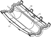
Fig. 1 is the perspective view of connector box.
Fig. 2 illustrates the connector box that is in open mode.
The use of different line separators in the central part of the connector box of Fig. 1 and 2 is shown to Fig. 3 and Fig. 4 n-lustrative.
Fig. 5 is the perspective view of the line separator of Fig. 3.
Fig. 6 illustrates the core component of the line separator of Fig. 5.
Fig. 7 illustrates the separating arm of the line separator of Fig. 5.
Fig. 8 illustrates the process on the core component that separating arm with Fig. 7 is installed in Fig. 6, shown in the core component part excised.
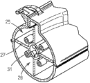
The use of line separator in the central part of the connector box of Fig. 1 and Fig. 2 of another form is shown to Fig. 9 n-lustrative.
Figure 10 illustrates the assembling of the line separator of Fig. 9.
Figure 11 illustrates the modification of the separating arm of Fig. 7.
Figure 12 illustrates the perspective view of another embodiment of line separator.
Figure 13 illustrates the core element of the line separator of Figure 12.
Figure 14 illustrates the separating arm of the line separator of Figure 12.
Embodiment
Fig. 1 illustrates embedded connector box 1, its be used for around and protection get into joint between two cable (not shown) of box along opposite direction through its end 3.Each end 3 comprises encapsulant ring 4, and it centers on and seal the crust of corresponding entering cable.
Fig. 2 illustrates the box 1 that is in open mode, can be closed around cable connector from this state box.Omitted the encapsulant ring 4 in the end 3 among the figure.Box 1 has substantial cylindrical central part 5, and in use, cable connector will be arranged in this central part, and tapered portion 7 extends to end 3 from this central part.The top of box (from figure, seeing) is two parts 5A, 5B, and these two parts meet along the top of box, and are hinged to the respective edges 6 of box bottom 5C, so that it can outwards open to position shown in Figure 2.Embedded joint cable is placed in the box of opening, and makes joint be positioned at central part 5, and cable is positioned at respective end portions 3.Then; Two top 5A, 5B of box are closed be incorporated in a little that 9 places are latched in together; Make encapsulant ring 4 and the cable sealed engagement that gets in the end 3; Be poured in box 1 through the filler opening 11 in the main body top suitable liquid sealing material (for example, appropriate resin) then and make its sclerosis.Exhaust outlet 13 in box 1 top allows air to leave box in filling process.
The formation of the embedded joint between two cables be usually directed to remove the end of cable sheath so that the line of two cables (perhaps, under the situation of multi-core cable, each line) can joint together.In some cases; For example when using suitable wiring connector that line is bonded together; The insulating material of thread end also is removed; And when relating to multi-core cable, between the regional center line that must the retention wire insulating material be removed (comprising connector (if existence)), and line that connects and the minimum range between the connector box outer surface.Under the situation of type low-voltage cable (that is, the voltage that cable is carried is not more than 1000V AC), guarantee that it is 5mm that the enough electricity of each line/connector are isolated required typical minimum range.When connector box had relatively little cross-sectional area (for example, 25mm2 or littler), such minimum range can especially be difficult to realization, but can use line separators guarantee such minimum range through the central part 5 at box 1, as will be described below.
Fig. 3 illustrates when box holds two 5 joints between the core cable, is used in the line separator 15 of first form in the box 1 of Fig. 1 and Fig. 2.The end of cable sheath and line insulating material are removed, and use the traditional electrical connector with each wire terminal of cable together.The part of the central part 5 of box 1 only is shown among Fig. 3, and remainder omits for clarity.Separator 15 (form that it removes from box 1 also is shown among Fig. 5) has 17, five separating arms 19 of cylindrical core and radially extends from core.Separating arm 19 around core 17 uniformly-spaced, five line receiving positions 21 of the space boundary between them, the electric connector 23 that the line 24 of 5 core cables is bonded together is separately positioned in the said line receiving positions, and is as shown in Figure 3.Arm 19 stretches out fully far engaging the inner surface of box 1, and because these arms are identical, so core 17 is arranged on the center with respect to arm basically in box.If desired, the cross-piece (not shown) can be set in the outer end of separating arm 19, with engaging between reinforcing arm and the box inner surface.
Fig. 4 illustrates the similar line separator 25 that is intended to be used for 4 core cables.Separator 25 is with the difference of the separator 15 of Fig. 3; It only has four arms 27 that radially extend; Therefore four line receiving positions 29 only are provided, and the electric connector 31 that the line (invisible) of 4 core cables is bonded together is separately positioned in the said line receiving positions.
The size of the core 17 in each of line separator 15,25 is selected as to be guaranteed electric connector 23, can keep specific minimum spacing between 31, and therefore, can keep specific minimum spacing between the joint line of two cables.
The assembling of the separator 15 of Fig. 3 and Fig. 5 will be described with reference to Fig. 6 to Fig. 8 now.At first will assembling process not described with reference to the joint cable.
Separator comprises core component shown in Figure 6 33 and four identical arm members 35 that each is as shown in Figure 7.Core component 33 provides core 17 and separating arm 19 of separator.The end of core 17 has conical entrance portion 37,39, and it all is found in Fig. 8.Each arm member 35 is a template, and length is similar to core 17, at one end has rigid hooks and forms thing 41, has the hook-forming thing 43 of resiliently flexible at the other end.Hook-forming thing 41,43 is shaped to engage in the conical entrance portion 37,39 of core, thereby arm member 35 is attached to core.Attach procedure has been shown among Fig. 8.At first rigid hooks is formed in the conical entrance portion 37 that thing 41 is bonded on core fully, can the hook-forming thing 43 of the resiliently flexible of arm member 35 other ends be snapped in the conical entrance portion 39 of the core other end then.Can in an identical manner other additional arm members 35 (in this case, three additional arm members) be attached to core 17, so that the line receiving positions 21 of requirement to be provided around core.
The separator 25 of Fig. 4 will be assembled in a similar manner.
The top that rigid hooks on the arm member 35 forms thing 41 is a wedge shape, with the inlet portion 37 that conveniently is inserted into core 17, especially when free space is limited owing to the existence of the arm member of having installed 35.Yet as alternative form, the hook-forming thing at arm member 35 two ends all can be resiliently flexible, thereby no longer need in the process of assembling separator, distinguish an end and the other end of arm member.
In practice, assemble separator 15,25 through at first core component 33 being arranged between the electric connector 23 that the line 24 with the joint cable is bonded together.The one separating arm 19 of core component 33 stretches out between two connectors 23, through with hand connector being pinched together, can shift core 17 onto center.Then, as stated arm member 35 is attached to core 17, each arm member inserts between the corresponding pair of connectors 23.Then, the cable connector that is assembled with separator 15 is arranged on the center of the connector box of opening 1 (Fig. 2), then can be as stated that connector box is closed and fill with resin.
The structure of arm member 35 allows it to move around core 17, thereby in connector box 1, takes the optimum position around core 17.Advantageously, arm member 35 is deflection slightly, so that its size that can conform to the space in the connector box 1 and adapt to the line 24 of joint cable.If desired, can arm member 35 be removed from core 17, thereby obtain providing the line separator of less line receiving positions through above-mentioned assembly program is reversed.
If desired, capable of using do not have the cylindrical core member of one separating arm 19 to construct separator 15,25, and the arm member 35 of requirement may be attached to said core component.Perhaps, can use the core component that comprises a more than one line separating arm.
In further retrofiting, shown in figure 11, each arm member 35 of separator 15,25 is provided with outward extending horizontal stripe 53 in both sides.On the one separating arm 19 (if existence) of the core component of separator, also similar horizontal stripe will be set.Horizontal stripe 53 is as block piece, in case the electric connector 23 of principal vertical line cable joint is outwards mobile away from the core 17 of separator, and guarantees to keep the required minimum range between connector 23 and the connector box 1.
Fig. 9 illustrates the line separator 45 of another form, and it is used for being similar to 5 core cables of the connector box of Fig. 1 and 2.As Fig. 3, the part of the central part 5 of connector box only is shown among Fig. 9, remainder omits for clarity.Separator 45 (form that it removes from box 1 and part is assembled also is shown among Figure 10) has 47, five separating arms 49 of real core and radially extends from this core.Arm 49 around core 47 uniformly-spaced, five line receiving positions 21 of the space boundary between them, in use, five joint line 23 of 5 core cables are separately positioned in the said line receiving positions.Arm 49 stretches out fully far with the inner surface of junction joint box 1, and because these arms are identical, so core 47 is located substantially on the center in the box.Cross-piece 51 with crooked outer surface is arranged on the outer end of arm 49, to guarantee the good fit with connector box 1 inner surface.
The core 47 of an arm 49 (49A refers to by label) and separator 45 forms, but the residue arm with the form snap of ball-and-socket joint on attached formation thing 50 set on the core, be star-like.Those arms can rotate on attached formation thing 50 slightly, make it can conform to the size of the line of interior space of connector box and joint cable.The line receiving positions 21 of lesser amt if desired, then one or more separating arms 49 can be omitted, and the position of residue arm can correspondingly be adjusted.
Should be appreciated that separator 45 is to be assembled between the electric connector of joint cable with separator 15, the 25 identical modes of Fig. 3 and Fig. 4.
The line separator 45 of Fig. 9 and Figure 10 does not have to extend along the length of the central part 5 of connector box 1, but can so revise if desired yet.If desired, the cross-piece 51 of separating arm 49 outer end can omit.
Another embodiment variant of line separator shown in Figure 12 58.Separator 58 has 59, five separating arms 52 of cylindrical core and radially extends from this core.With mutually the same pitch arrangement, five line receiving positions 21 of the area limiting between them can corresponding be arranged in line 24 electric connectors 23 connected to one another of five line cables in the said line receiving positions around core 59 for separating arm 52.Arm 52 stretches out enough far with the inner surface of touching sleeve pipe 1, and because these arms are identical, so in the middle of core 29 is arranged in respect to arm in sleeve pipe basically.The size of the core 59 in the line separator 58 is selected by this way, makes to guarantee to keep electric connector 23, the specific minimum spacing between 31, and the specific minimum spacing between the connecting line of the cable that therefore keeps connecting.
Separator provides core element 60 (shown in Figure 13) the arm element 54 identical with four (it respectively has outward appearance shown in Figure 14).Core element 60 provides core 59 and separating arm 52 of separator.The end of core 59 has taper receiving positions 37,39.Each arm element 54 is a template, and length at one end has rigid hooks and forms thing 41 corresponding to the length of core 59, has the hook-forming thing 43 of resiliently flexible at the other end.Hook-forming thing 41,43 is shaped so that in its taper receiving positions that is bonded on core 37,39, thereby element 54 is fixed on the core.Attach procedure is corresponding to attach procedure shown in Figure 8.The top that rigid hooks on the arm element 54 forms thing 41 is designed to wedge shape, with convenient hook is introduced in the receiving positions 37 of core 59, especially when free space is limited owing to the existence of the arm element of having installed 54.Yet as other a kind of selection, the hook-forming thing at arm element 54 two ends all can be designed to resiliently flexible, thereby has avoided in the process of assembling separator 58, must distinguishing an end and the other end of arm element.
The structure of arm element 54 allows it to move around core 59, in joint sleeve 1, presents the optimum position around core 59 in this course.Advantageously, arm element 54 is deflection slightly, adapts to the size of the line 24 of space and connection cable in joint sleeve 1 to allow it.If desired, in order to obtain having the line separator that less line is admitted the zone, can arm element 54 be removed from core 59 through carrying out above-mentioned assembling process with the order of putting upside down.
Above-mentioned line separator 15,25,45,58 can form preferred insulative material by any suitable material of the environmentally compatible that will be used for separator.For guaranteeing separator and being poured into the preferred material that the well attached between the resin in the connector box selects is Merlon (each parts of separator can be formed by this material through molding process).Can use other suitable material and manufacturing process.
The line separator that illustrates and describes above has simple structure, but can keep the regulation minimum range between the line of multi-core cable of connector and joint.Said minimum range is limited the thickness of separating arm, and how the diameter of the electric connector that no matter is used for line is engaged all will keep (supposing that it is in normal ranges).If the adjacent setting in the center of electric connector and separator, then the latter also will play the effect of the minimum range between limiting connector/line and the connector box on every side.The advantage of the simple structure of said separator is that it is easy to make and can in connector box, not occupy too much space.It can be only easily assembled by two types parts, makes it be easy to install under the condition at the scene, and can be adapted to hold the cable core of varying number.
Should be appreciated that except illustrated in figures 1 and 2 the line separator that illustrates and describes above can be used for other joint configurations and various forms of connector box, if necessary can suitably revise to take into account the space in the box that holds separator those.Other forms of connector box is described in for example EP 1 122571 (Corning Cable Systems), DE 296 19 002U (Paul Jordan), DE 199 58 982 (Hoehne GmbH) and DE 42 22 959 (Cellpack AG) to some extent.
Claims (15)
1. a separator is used for separating at the connecting line of connector box with the multi-core cable of joint, and said separator comprises core and a plurality of separating arm, and said separating arm stretches out from said core, to be defined for a plurality of positions of admitting said connecting line around said core; In the wherein said separating arm at least some are attached to said core individually, can change the quantity of line receiving positions thus through the quantity that change is attached to the separating arm of said core.
2. separator according to claim 1, wherein said core are shaped so that other separating arm can be attached to this core.
3. according to each described separator in the aforementioned claim, wherein said core has permanent attachment at least one separating arm to it.
4. according to each described separator in the aforementioned claim, wherein said core is an elongated shape, and said separating arm extends along the length of said core.
5. according to each described separator in the aforementioned claim, wherein said core is provided with respect to said separating arm between two parties.
6. separator according to claim 5, wherein said core has circular cross section basically, and said separating arm roughly radially extends from it.
7. according to each described separator in the aforementioned claim, wherein attached separately said separating arm snap is to said core.
8. according to each described separator in the aforementioned claim, wherein said separating arm can move with respect to said core, to regulate the size of said line receiving positions.
9. according to each described separator in the aforementioned claim, also comprise the block piece that is positioned on the said separating arm, to limit said connecting line moving away from said core.
10. cable connector external member, said cable connector external member comprises each described separator in the aforementioned claim that combines with connector box; Said connector box is configured as the joint of sealing between the multi-core cable, makes each joint line of said cable be arranged in a corresponding line receiving positions of the said line receiving positions of said line separator.
11. external member according to claim 10, the outer end of the separating arm of wherein said line separator are configured as the connector box around supporting.
12. separator external member that is used for assembling each described separator of claim 1-9; Said external member comprises core and a plurality of separating arm; Said separating arm can be attached to said core individually; Stretching out, and limit the line receiving positions of requirement around said core from said core component.
13. a method that between multi-core cable, forms joint, said method comprises step: provide claim 12 described external member; And separating arm is attached to said core, to form the corresponding line receiving positions of quantity of the connecting line in quantity and the said joint.
14. the joint between the multi-core cable, wherein the connecting line of joint cable is arranged in the homologous lines receiving positions of each described separator of claim 1 to 9.
15. cable connector according to claim 14, wherein said separator and said connecting line are housed inside in the connector box.
Applications Claiming Priority (5)
| Application Number | Priority Date | Filing Date | Title |
|---|---|---|---|
| GB0921073A GB0921073D0 (en) | 2009-12-02 | 2009-12-02 | Wire separator suitable for use in a cable splice enclosure |
| GB0921073.3 | 2009-12-02 | ||
| DE201020002004 DE202010002004U1 (en) | 2010-02-05 | 2010-02-05 | Spacers for cores for use in cable connection sleeves |
| DE202010002004.2 | 2010-02-05 | ||
| PCT/US2010/058325 WO2011068788A1 (en) | 2009-12-02 | 2010-11-30 | Wire separator suitable for use in a cable splice enclosure |
Publications (1)
| Publication Number | Publication Date |
|---|---|
| CN102640373A true CN102640373A (en) | 2012-08-15 |
Family
ID=44115242
Family Applications (1)
| Application Number | Title | Priority Date | Filing Date |
|---|---|---|---|
| CN2010800545817A Pending CN102640373A (en) | 2009-12-02 | 2010-11-30 | Wire separator suitable for use in a cable splice enclosure |
Country Status (11)
| Country | Link |
|---|---|
| US (1) | US20120267146A1 (en) |
| EP (1) | EP2507883A4 (en) |
| JP (1) | JP2013513352A (en) |
| KR (1) | KR20120099085A (en) |
| CN (1) | CN102640373A (en) |
| BR (1) | BR112012012861A2 (en) |
| CA (1) | CA2780999A1 (en) |
| MX (1) | MX2012005897A (en) |
| RU (1) | RU2516384C2 (en) |
| TW (1) | TW201203764A (en) |
| WO (1) | WO2011068788A1 (en) |
Cited By (1)
| Publication number | Priority date | Publication date | Assignee | Title |
|---|---|---|---|---|
| CN108233279A (en) * | 2016-12-22 | 2018-06-29 | 库迈思控股股份公司 | For operating the device and method of inner wire |
Families Citing this family (4)
| Publication number | Priority date | Publication date | Assignee | Title |
|---|---|---|---|---|
| US9953742B2 (en) | 2013-03-15 | 2018-04-24 | General Cable Technologies Corporation | Foamed polymer separator for cabling |
| AR104561A1 (en) * | 2014-06-06 | 2017-08-02 | General Cable Tech Corp | CABLE SEPARATORS |
| IT202100004853A1 (en) * | 2021-03-04 | 2022-09-04 | Antonio Carpino | MODULAR SEPARATOR FOR THE MECHANICAL AND ELECTRICAL SEPARATION OF THE POLES IN JOINTS FOR MULTIPOLE ELECTRIC CABLES |
| US20230135895A1 (en) * | 2021-10-28 | 2023-05-04 | Abb Schweiz Ag | Device and method for separating wires and sealing a conduit |
Citations (5)
| Publication number | Priority date | Publication date | Assignee | Title |
|---|---|---|---|---|
| DE3527658A1 (en) * | 1985-08-01 | 1987-02-12 | Cellpack Ag | Device for insulating cable ends |
| US5789711A (en) * | 1996-04-09 | 1998-08-04 | Belden Wire & Cable Company | High-performance data cable |
| JP2003284216A (en) * | 2002-03-25 | 2003-10-03 | Nikkai Ns Kk | Multiple cable installation spacer |
| US6639152B2 (en) * | 2001-08-25 | 2003-10-28 | Cable Components Group, Llc | High performance support-separator for communications cable |
| CN101093934A (en) * | 2006-06-23 | 2007-12-26 | 3M创新有限公司 | End cover of cable sheath |
Family Cites Families (13)
| Publication number | Priority date | Publication date | Assignee | Title |
|---|---|---|---|---|
| SE364099B (en) * | 1972-01-10 | 1974-02-11 | L Lilja | |
| US4046408A (en) * | 1973-08-03 | 1977-09-06 | Steven Ausnit | Omni-directional fastener |
| DE3445489C2 (en) * | 1984-12-13 | 1986-11-20 | Messerschmitt-Bölkow-Blohm GmbH, 8012 Ottobrunn | Device for fastening several electrical lines in an aircraft |
| US4804020A (en) * | 1987-05-27 | 1989-02-14 | Proprietary Technology, Inc. | Conduit liner assembly and method for installation |
| US5320312A (en) * | 1993-05-05 | 1994-06-14 | Stainless, Inc. | Cable cluster mount |
| CZ293492B6 (en) * | 1994-09-21 | 2004-05-12 | N@Áv@Áraychemás@Áa | Cable splice closure |
| EP1151513B1 (en) * | 1998-10-23 | 2002-11-27 | Tyco Electronics Raychem NV | A seal for a closure and a closure incorporating the seal |
| ES2252921T3 (en) * | 1999-03-23 | 2006-05-16 | Gaimont Universal Ltd. B.V.I. | EXTRUSIONED TUBULAR DEVICE. |
| US6099345A (en) * | 1999-04-23 | 2000-08-08 | Hubbell Incorporated | Wire spacers for connecting cables to connectors |
| US6304698B1 (en) * | 1999-09-22 | 2001-10-16 | Milliken & Company | Conduit insert for optical fiber cable |
| US6710249B1 (en) * | 2002-09-13 | 2004-03-23 | Sandra L. Denton | Wire separator |
| US7442884B2 (en) * | 2004-08-30 | 2008-10-28 | 3M Innovative Properties Company | Sealing member for enclosures |
| US7271342B2 (en) * | 2005-12-22 | 2007-09-18 | Adc Telecommunications, Inc. | Cable with twisted pair centering arrangement |
-
2010
- 2010-11-30 CN CN2010800545817A patent/CN102640373A/en active Pending
- 2010-11-30 KR KR1020127016576A patent/KR20120099085A/en not_active Application Discontinuation
- 2010-11-30 US US13/509,932 patent/US20120267146A1/en not_active Abandoned
- 2010-11-30 MX MX2012005897A patent/MX2012005897A/en active IP Right Grant
- 2010-11-30 BR BR112012012861A patent/BR112012012861A2/en not_active IP Right Cessation
- 2010-11-30 WO PCT/US2010/058325 patent/WO2011068788A1/en active Application Filing
- 2010-11-30 EP EP10834997.8A patent/EP2507883A4/en not_active Withdrawn
- 2010-11-30 CA CA2780999A patent/CA2780999A1/en not_active Abandoned
- 2010-11-30 JP JP2012542129A patent/JP2013513352A/en active Pending
- 2010-11-30 RU RU2012119352/07A patent/RU2516384C2/en not_active IP Right Cessation
- 2010-12-01 TW TW099141758A patent/TW201203764A/en unknown
Patent Citations (5)
| Publication number | Priority date | Publication date | Assignee | Title |
|---|---|---|---|---|
| DE3527658A1 (en) * | 1985-08-01 | 1987-02-12 | Cellpack Ag | Device for insulating cable ends |
| US5789711A (en) * | 1996-04-09 | 1998-08-04 | Belden Wire & Cable Company | High-performance data cable |
| US6639152B2 (en) * | 2001-08-25 | 2003-10-28 | Cable Components Group, Llc | High performance support-separator for communications cable |
| JP2003284216A (en) * | 2002-03-25 | 2003-10-03 | Nikkai Ns Kk | Multiple cable installation spacer |
| CN101093934A (en) * | 2006-06-23 | 2007-12-26 | 3M创新有限公司 | End cover of cable sheath |
Cited By (3)
| Publication number | Priority date | Publication date | Assignee | Title |
|---|---|---|---|---|
| CN108233279A (en) * | 2016-12-22 | 2018-06-29 | 库迈思控股股份公司 | For operating the device and method of inner wire |
| CN108233279B (en) * | 2016-12-22 | 2020-12-18 | 库迈思控股股份公司 | Device and method for operating an inner conductor |
| US10903631B2 (en) | 2016-12-22 | 2021-01-26 | Komax Holding Ag | Device and method for manipulating an inner conductor |
Also Published As
| Publication number | Publication date |
|---|---|
| EP2507883A1 (en) | 2012-10-10 |
| JP2013513352A (en) | 2013-04-18 |
| BR112012012861A2 (en) | 2017-10-10 |
| RU2516384C2 (en) | 2014-05-20 |
| CA2780999A1 (en) | 2011-06-09 |
| US20120267146A1 (en) | 2012-10-25 |
| RU2012119352A (en) | 2014-01-10 |
| EP2507883A4 (en) | 2014-04-16 |
| TW201203764A (en) | 2012-01-16 |
| KR20120099085A (en) | 2012-09-06 |
| MX2012005897A (en) | 2012-06-19 |
| WO2011068788A1 (en) | 2011-06-09 |
Similar Documents
| Publication | Publication Date | Title |
|---|---|---|
| US8981222B2 (en) | Cable termination device, a method for prefabricating a cable termination device and a method for achieving a cable termination | |
| CN102640373A (en) | Wire separator suitable for use in a cable splice enclosure | |
| US9509110B1 (en) | Adapter for LED strip light | |
| EP2712473B1 (en) | A cable termination device, a method for prefabricating a cable termination device and a method for achieving a cable termination | |
| US20080011501A1 (en) | Closed electrical enclosure | |
| RU2008151378A (en) | ELECTRICAL CONNECTOR, PLUG BLOCK FOR SUCH CONNECTOR AND METHOD FOR PRODUCING THEM | |
| CN206610949U (en) | Connector and connector assembly for connecting wire | |
| CN107171095B (en) | Cable plug-in type connector for transformer | |
| US20120097445A1 (en) | Electrical Connection Device Using a Cable Gland and Method of Manufacturing Thereof | |
| US10431352B2 (en) | Cable and method for producing a cable | |
| CN207021629U (en) | A kind of pipe bus connection structure for switch cubicle | |
| KR100717889B1 (en) | A Branch Device For The Ceiling Distribution Wires | |
| AU2019226253B2 (en) | Packing member for waterproof electric connector | |
| CN202772091U (en) | Upper die cone for high voltage fuse | |
| KR101110232B1 (en) | Electric lamp cable | |
| CN105322367A (en) | Detachable electric wire | |
| KR200444333Y1 (en) | Neutral conductor arrangement device | |
| CN110854688A (en) | Power distribution device | |
| KR100717890B1 (en) | A Branch Device For The Ceiling Distribution Wires | |
| KR100689872B1 (en) | A bus duct | |
| US9537247B2 (en) | Detachable cable joint with three sockets | |
| KR20230086177A (en) | Structure For Connecting Electric Wire Cable And Distributing Box | |
| CN117175228A (en) | Quick connection lug and application method thereof |
Legal Events
| Date | Code | Title | Description |
|---|---|---|---|
| C06 | Publication | ||
| PB01 | Publication | ||
| C10 | Entry into substantive examination | ||
| SE01 | Entry into force of request for substantive examination | ||
| C02 | Deemed withdrawal of patent application after publication (patent law 2001) | ||
| WD01 | Invention patent application deemed withdrawn after publication |
Application publication date: 20120815 |