CN102616952B - Kitchen oil-water residue separation device - Google Patents

Kitchen oil-water residue separation device Download PDF

Info

Publication number
CN102616952B
CN102616952B CN 201210116684 CN201210116684A CN102616952B CN 102616952 B CN102616952 B CN 102616952B CN 201210116684 CN201210116684 CN 201210116684 CN 201210116684 A CN201210116684 A CN 201210116684A CN 102616952 B CN102616952 B CN 102616952B
Authority
CN
China
Prior art keywords
water
liquid level
chamber
water outlet
oil
Prior art date
Legal status (The legal status is an assumption and is not a legal conclusion. Google has not performed a legal analysis and makes no representation as to the accuracy of the status listed.)
Active
Application number
CN 201210116684
Other languages
Chinese (zh)
Other versions
CN102616952A (en
Inventor
陈礼国
Current Assignee (The listed assignees may be inaccurate. Google has not performed a legal analysis and makes no representation or warranty as to the accuracy of the list.)
SHANGHAI ZTEC ENVIRONMENTAL TECHNOLOGY Co Ltd
Original Assignee
SHANGHAI ZTEC ENVIRONMENTAL TECHNOLOGY Co Ltd
Priority date (The priority date is an assumption and is not a legal conclusion. Google has not performed a legal analysis and makes no representation as to the accuracy of the date listed.)
Filing date
Publication date
Application filed by SHANGHAI ZTEC ENVIRONMENTAL TECHNOLOGY Co Ltd filed Critical SHANGHAI ZTEC ENVIRONMENTAL TECHNOLOGY Co Ltd
Priority to CN 201210116684 priority Critical patent/CN102616952B/en
Publication of CN102616952A publication Critical patent/CN102616952A/en
Application granted granted Critical
Publication of CN102616952B publication Critical patent/CN102616952B/en
Active legal-status Critical Current
Anticipated expiration legal-status Critical

Links

Images

Abstract

The invention discloses a kitchen oil-water residue separation device, which is characterized by comprising an intake chamber, an inflow liquid level control room, a three-phase separation chamber, an effluent liquid level control room, a water outlet room, an oil chamber and a dissolved air pump which are arranged in a main bady, wherein a filter residue frame is arranged in the intake chamber; a dissolved air contactor, an oil collecting and discharging cover, and a water outlet ring pipe are arranged in the three-phase separation chamber; a slag collecting hopper is arranged on the lower part of the three-phase separation chamber; the inflow liquid level control room is connected with the dissolved air contactor through a water inlet mixing pipe; the effluent liquid level control room is communicated with a water outlet overflow weir arranged in the water outlet room; an outlet of the dissolved air pump is communicated with the water inlet mixing pipe through a dissolved air pipe; an inlet of the dissolved air pump is connected with the water outlet room through a pipeline; and the oil collecting and discharging cover is communicated with the oil chamber through an oil discharging hole. Compared with the prior art, the kitchen oil-water residue separation device has a novel design, an ingenious structure, low manufacturing cost, convenience in operation, high efficiency for separating oil, water and slag, convenience in equipment maintenance, and low operation cost; and is environment protection equipment with wide application range, energy conservation and emission reduction.

Description

A kind of meal kitchen profit slag tripping device
Technical field
The present invention relates to the environmental protection equipment technical field, specifically a kind of profit slag tripping device for changing food waste.
Background technology
The changing food wastes such as a large amount of kitchen waste waters and swill all will be discharged every day in the dining room, if kitchen waste water and swill are not processed and directly discharging, then contain the obstruction that a large amount of swills and profit cause sewer line easily in the changing food waste, not only increase the processing load of Sewage Plant, fish for the potential safety hazards such as sewer oil and presence of fire but also exist the lawless person.
At present, the dining room is to the oily water separation of kitchen waste water or swill, generally adopt all with swash plate or inclined tube-type oil trap and air-flotation type oil trap, swash plate or inclined tube-type oil trap exist oily water separation efficient low, and be not good to tiny oil bloom treatment effect simultaneously, do not reach the relevant criterion of national regulation, and the air-flotation type oil trap, because the frizing equipment that adopts electric energy to drive, power consumption is large, seem very heavy at the processing swill, the operation and maintenance cost of mechanical means is higher simultaneously.
Summary of the invention
The objective of the invention is a kind of meal kitchen profit slag tripping device of designing for the deficiencies in the prior art, adopt profit dissolved air flotation and automatic collecting displacement configuration, make profit slag three phase separation, simple in structure, cost is low, and, energy-saving and emission-reduction, oily water separation efficient is high, and maintenance of the equipment is convenient, and operation and maintenance cost is low.
Realize that concrete technical scheme of the present invention is: a kind of meal kitchen profit slag tripping device, be characterized in that this device forms by being arranged on intrinsic intake chamber, water inlet liquid level watch-keeping cubicle, three phase separation chamber, water outlet liquid level watch-keeping cubicle, water-supplying chamber, accumulator and air dissolved pump, the three phase separation chamber is arranged on the centre of box-like body, three phase separation chamber one side arranges intake chamber and water inlet liquid level watch-keeping cubicle, its opposite side arranges water outlet liquid level watch-keeping cubicle, water-supplying chamber and accumulator, and the below of accumulator arranges air dissolved pump; Be provided with the filter residue frame in the intake chamber, intake chamber is provided with into the water overflow weir with water inlet liquid level watch-keeping cubicle and is communicated with; Indoor molten gas contactor, collection oil extraction cover and the water outlet endless tube of being provided with of three phase separation, bottom, three phase separation chamber is provided with slag gathering hopper, molten gas contactor is the drum that the top is provided with reflector, molten gas contactor is fixed on the slag gathering hopper by support, collection oil extraction cover is arranged on the top of reflector and is fixedly connected with the three phase separation chamber interior walls, the water outlet endless tube is the annulus that is provided with several prosopyles, and water outlet endless tube 7 is set in outside the molten gas contactor and is communicated with water outlet liquid level watch-keeping cubicle by rising pipe; Water inlet liquid level watch-keeping cubicle is connected with molten gas contactor by the water inlet mixing tube; Water outlet liquid level watch-keeping cubicle is provided with effluent overflow weir water with water-supplying chamber and is communicated with; The air dissolved pump outlet is communicated with the water inlet mixing tube by Gas dissolving pipe, and the air dissolved pump import connects water-supplying chamber by pipeline; Collection oil extraction cover is communicated with accumulator by outlet-port.
Described filter residue frame is made of the porous water filtration plate of bottom and filter screen all around, and filter residue frame top is provided with handle, and filter residue frame one side is provided with flowing hole.
Described intake chamber, water-supplying chamber, slag gathering hopper and accumulator are respectively equipped with water inlet pipe, water shoot, scum pipe and oil exit pipe.
Described body top cover is provided with inspection port.
The present invention compared with prior art has modern design, delicate structure, and cost is low, and is easy to operate, and the separation efficiency of oil, water and slag is high, and maintenance of the equipment is convenient, and working cost is low, is a kind of applied widely, energy-saving and emission-reduction and environmental protection equipment.
Description of drawings
Accompanying drawing 1 is structural representation of the present invention;
Accompanying drawing 2 is the A-A sectional view of Fig. 1;
Accompanying drawing 3 is the B-B sectional view of Fig. 1;
Accompanying drawing 4 is the C-C sectional view of Fig. 1;
Accompanying drawing 5 is the D-D sectional view of Fig. 2;
Accompanying drawing 6 ~ accompanying drawing 8 is filter residue mount structure synoptic diagram;
Accompanying drawing 9 is water outlet endless tube structural representation;
Accompanying drawing 10 is work synoptic diagram of the present invention.
Embodiment
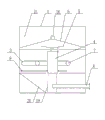
Consult accompanying drawing 1, the present invention is comprised of the intake chamber 11, water inlet liquid level watch-keeping cubicle 12, three phase separation chamber 21, water outlet liquid level watch-keeping cubicle 22, water-supplying chamber 23, accumulator 24 and the air dissolved pump 26 that are arranged in the body 1, three phase separation chamber 21 is arranged on the centre of box-like body 1, three phase separation chamber 21 1 sides arrange intake chamber 11 and water inlet liquid level watch-keeping cubicle 12, its opposite side arranges water outlet liquid level watch-keeping cubicle 22, water-supplying chamber 23 and accumulator 24
The below of accumulator 24 arranges air dissolved pump 26; Be provided with filter residue frame 2 in the intake chamber 11, intake chamber 11 is provided with into water overflow weir 17 with water inlet liquid level watch-keeping cubicle 12 and is communicated with; Be provided with molten gas contactor 4, collection oil extraction cover 6 and water outlet endless tube 7 in the three phase separation chamber 21,21 bottoms, three phase separation chamber are provided with slag gathering hopper 20, molten gas contactor 4 is provided with the drum of reflector 5 for the top, molten gas contactor 4 is fixed on the slag gathering hopper 20 by support 19, collection oil extraction cover 6 is arranged on the top of reflector 5 and is fixedly connected with three phase separation chamber 21 inwalls, water outlet endless tube 7 is for being provided with the annulus of several prosopyles 32, and water outlet endless tube 7 is set in outside the molten gas contactor 4 and is communicated with water outlet liquid level watch-keeping cubicle 22 by rising pipe 37; The liquid level of intaking watch-keeping cubicle 12 is connected with molten gas contactor 4 by water inlet mixing tube 3; Water outlet liquid level watch-keeping cubicle 22 is provided with effluent overflow weir water 27 with water-supplying chamber 23 and is communicated with; Air dissolved pump 26 outlets are communicated with water inlet mixing tube 3 by Gas dissolving pipe 9, and air dissolved pump 26 imports connect water-supplying chamber 23 by pipeline; Collection oil extraction cover 6 is communicated with accumulator 24 by outlet-port 31; Body 1 both sides are provided with ventilating pit 14, and body 1 top cover is provided with inspection cover 18.
Consult accompanying drawing 2 ~ accompanying drawing 3, be provided with filter residue frame 2 in the intake chamber 11, intake chamber 11 is provided with into water overflow weir 17 with water inlet liquid level watch-keeping cubicle 12 and is communicated with, and intake chamber 11 is provided with water inlet pipe 38; Collection oil extraction cover 6 is fixedly connected with three phase separation chamber 21 inwalls, and collection oil extraction cover 6 is provided with central through hole 16, and collection oil extraction cover 6 is communicated with accumulator 24 by outlet-port 31, and accumulator 24 is provided with oil exit pipe 29; Water outlet endless tube 7 is for being provided with the annulus of several prosopyles 32, and water outlet endless tube 7 is set in outside the molten gas contactor 4 and is communicated with water outlet liquid level watch-keeping cubicle 22 by rising pipe 37; Water outlet liquid level watch-keeping cubicle 22 is provided with effluent overflow weir water 27 with water-supplying chamber 23 and is communicated with, and water-supplying chamber 23 is provided with water shoot 28.
Consult accompanying drawing 4, air dissolved pump 26 is arranged on the below of water-supplying chamber's 23 1 sides and accumulator 24, the outlet of air dissolved pump 26 is communicated with water inlet mixing tube 3 by Gas dissolving pipe 9, the import of air dissolved pump 26 connects water-supplying chamber 23 by pipeline, the liquid level of intaking watch-keeping cubicle 12 is connected with molten gas contactor 4 by water inlet mixing tube 3, water outlet endless tube 7 is for being provided with the annulus of several prosopyles 32, and water outlet endless tube 7 is communicated with water outlet liquid level watch-keeping cubicle 22 by rising pipe 37.
Consult accompanying drawing 5, be provided with molten gas contactor 4 in the three phase separation chamber 21, collection oil extraction cover 6 and water outlet endless tube 7,21 bottoms, three phase separation chamber are provided with slag gathering hopper 20, molten gas contactor 4 is provided with the drum of reflector 5 for the top, molten gas contactor 4 is fixed on the slag gathering hopper 20 by support 19, collection oil extraction cover 6 is arranged on the top of reflector 5 and is fixedly connected with three phase separation chamber 21 inwalls, integrate oil extraction cover 6 as the top cover of bucket shape, and maximum by outlet-port 31 lopsidedness degree, assemble like this can flowing automatically of oil on the collection oil extraction cover 6 and flow into accumulator 24, water outlet endless tube 7 is set in outside the molten gas contactor 4, and slag gathering hopper 20 is provided with scum pipe 8.
Consult accompanying drawing 6 ~ accompanying drawing 8, filter residue frame 2 is made of porous water filtration plate 44 and the filter screen all around 43 of bottom, the aperture of porous water filtration plate 44 is that 5mm(can set according to practical situation), aperture upper part of filter screen 43 is 10mm*10mm, lower part is 5mm*5mm, filter residue frame 2 tops are provided with handle 42, filter residue frame 2 one sides are provided with flowing hole 41, flowing hole 41 is arranged on the position corresponding with water inlet pipe 38 and aperture greater than the aperture of water inlet pipe 38, in case the mouth of pipe misplaces and blocks water inlet pipe 38, filter residue frame 2 is arranged on the stainless steel stent in the intake chamber 11, and two handles 42 in the top of filter residue frame 2 are convenient to take out filter residue frame 2 and are dumped rubbish.
Consult accompanying drawing 9, water outlet endless tube 7 is for being provided with the annulus of several prosopyles 32, and water outlet endless tube 7 is communicated with water outlet liquid level watch-keeping cubicle 22 by rising pipe 37.
Consult accompanying drawing 10, the present invention is like this work: first clear water is injected in water-supplying chamber 23, swill enters intake chamber 11 by water inlet pipe 38, profit after the floating matters such as filter residue frame 2 interception larger particles and dish leaf flows into water inlet liquid level watch-keeping cubicle 12 by water inlet overflow weir 17, water inlet overflow weir 17 has guaranteed that the oil slick of intake chamber 11 preferentially enters into water liquid level watch-keeping cubicle 12, do not make oil slick be collected in intake chamber 11, the molten gas contactor 4 that water inlet liquid level watch-keeping cubicle 12 is sent into profit in the three phase separation chamber 21 by water inlet mixing tube 3 carries out oil, the three phase separation of water and slag, at this moment, air dissolved pump 26 fully mixes water-supplying chamber's 23 clear water of the air that sucks and inspiration and becomes dissolved air water, sends into molten gas contactor 4 by Gas dissolving pipe 9 and water inlet mixing tube 3 with profit and carries out dissolved air flotation.Behind dissolved air water and the oil mixing with water, the microbubble that tiny oil droplet is discharged by tiny dissolved air water is wrapped to form the gas and oil zoarium, and density lightens, accelerated upflow velocity, gas and oil is fit to rise, and assembles at the reflector 5 at molten gas contactor 4 tops to become large, accelerates its upflow velocity.In three phase separation chamber 21, thin slag then falls to slag gathering hopper 20, the oil droplet that the gas and oil zoarium is taken out of enters the upper strata oil collecting zone by the central through hole 16 of collection oil extraction cover 6, oil droplet enters accumulator 24 in 6 gatherings of collection oil extraction cover by outlet-port 31, then discharged by oil exit pipe 29, water after the separation then enters water outlet endless tube 7 and enters water outlet liquid level watch-keeping cubicle 22 by rising pipe 37 by prosopyle 32, then entering water-supplying chamber 23 through effluent overflow weir water 27 is discharged by water shoot 28, the thin slag that falls to slag gathering hopper 20 is then discharged by scum pipe 8, prosopyle 32 on the water outlet endless tube 7, water outlet is even around keeping, reduce simultaneously the fluctuation of water, oil supply, water separates with slag builds a metastable environment.After dissolved air water and former water mix, the microbubble parcel that tiny oil droplet is discharged by dissolved air water, density lightens, and has accelerated upflow velocity, has improved the separating effect of oil and water.Reflector 5 utilizes that swash plate principle and shallow-layer are theoretical to accelerate tiny oil droplet and gather and become larger oil droplet, be convenient to the dissolved air flotation of oil and water, simultaneously because its compartmentation, avoid and the current fluctuation that collects under the oil extraction cover 6, affect the stability of oil extraction, air dissolved pump 26 is automatically control, when having water to enter, start, stop rear delay to current and stopped in one minute, to guarantee fully separating of oil, water and slag, the while saves energy.
More than just the present invention is further illustrated, is not to limit this patent, all for the present invention's equivalence enforcement, all should be contained within the claim scope of this patent.

Claims (4)

1. meal kitchen profit slag tripping device, it is characterized in that this device forms by being arranged on intrinsic intake chamber, water inlet liquid level watch-keeping cubicle, three phase separation chamber, water outlet liquid level watch-keeping cubicle, water-supplying chamber, accumulator and air dissolved pump, the three phase separation chamber is arranged on the centre of box-like body, three phase separation chamber one side arranges intake chamber and water inlet liquid level watch-keeping cubicle, its opposite side arranges water outlet liquid level watch-keeping cubicle, water-supplying chamber and accumulator, and the below of accumulator arranges air dissolved pump; Be provided with the filter residue frame in the intake chamber, intake chamber is provided with into the water overflow weir with water inlet liquid level watch-keeping cubicle and is communicated with; Indoor molten gas contactor, collection oil extraction cover and the water outlet endless tube of being provided with of three phase separation, bottom, three phase separation chamber is provided with slag gathering hopper, molten gas contactor is the drum that the top is provided with reflector, molten gas contactor is fixed on the slag gathering hopper by support, collection oil extraction cover is arranged on the top of reflector and is fixedly connected with the three phase separation chamber interior walls, the water outlet endless tube is the annulus that is provided with several prosopyles, and the water outlet endless tube is set in outside the molten gas contactor and is communicated with water outlet liquid level watch-keeping cubicle by rising pipe; Water inlet liquid level watch-keeping cubicle is connected with molten gas contactor by the water inlet mixing tube; Water outlet liquid level watch-keeping cubicle is provided with effluent overflow weir water with water-supplying chamber and is communicated with; The air dissolved pump outlet is communicated with the water inlet mixing tube by Gas dissolving pipe, and the air dissolved pump import connects water-supplying chamber by pipeline; Collection oil extraction cover is communicated with accumulator by outlet-port.
2. described meal kitchen profit slag tripping device according to claim 1 is characterized in that described filter residue frame is made of the porous water filtration plate of bottom and filter screen all around, and filter residue frame top is provided with handle, and filter residue frame one side is provided with flowing hole.
3. described meal kitchen profit slag tripping device according to claim 1 is characterized in that described intake chamber, water-supplying chamber, slag gathering hopper and accumulator are respectively equipped with water inlet pipe, water shoot, scum pipe and oil exit pipe.
4. described meal kitchen profit slag tripping device according to claim 1 is characterized in that described body top cover is provided with inspection port.
CN 201210116684 2012-04-20 2012-04-20 Kitchen oil-water residue separation device Active CN102616952B (en)

Priority Applications (1)

Application Number Priority Date Filing Date Title
CN 201210116684 CN102616952B (en) 2012-04-20 2012-04-20 Kitchen oil-water residue separation device

Applications Claiming Priority (1)

Application Number Priority Date Filing Date Title
CN 201210116684 CN102616952B (en) 2012-04-20 2012-04-20 Kitchen oil-water residue separation device

Publications (2)

Publication Number Publication Date
CN102616952A CN102616952A (en) 2012-08-01
CN102616952B true CN102616952B (en) 2013-04-24

Family

ID=46557234

Family Applications (1)

Application Number Title Priority Date Filing Date
CN 201210116684 Active CN102616952B (en) 2012-04-20 2012-04-20 Kitchen oil-water residue separation device

Country Status (1)

Country Link
CN (1) CN102616952B (en)

Families Citing this family (4)

* Cited by examiner, † Cited by third party
Publication number Priority date Publication date Assignee Title
CN102825061A (en) * 2012-09-10 2012-12-19 顾家华 Treatment method for kitchen swill source and treatment equipment therefor
CN104591383B (en) * 2015-01-29 2016-03-23 浦城正大生化有限公司 Egsb anaerobic reactor
CN109480667B (en) * 2018-11-20 2020-12-25 安徽省冠腾信息科技有限公司 Multifunctional washing device for bathroom
CN109811417B (en) * 2019-03-18 2024-02-06 江苏恒力化纤股份有限公司 Multifunctional circular blowing correction device

Citations (4)

* Cited by examiner, † Cited by third party
Publication number Priority date Publication date Assignee Title
CN2579879Y (en) * 2002-11-01 2003-10-15 左图强 Oil and water separator for removing slag
CA2635792A1 (en) * 2008-06-12 2009-12-12 Jan A. Korzeniowski Produced water treatment system
CN201525784U (en) * 2009-09-08 2010-07-14 肖利民 Air floatation type automatic oil-water separator for restaurant waste water
CN202542968U (en) * 2012-04-20 2012-11-21 上海在田环境科技有限公司 Oil-water residue separating device of kitchen

Patent Citations (4)

* Cited by examiner, † Cited by third party
Publication number Priority date Publication date Assignee Title
CN2579879Y (en) * 2002-11-01 2003-10-15 左图强 Oil and water separator for removing slag
CA2635792A1 (en) * 2008-06-12 2009-12-12 Jan A. Korzeniowski Produced water treatment system
CN201525784U (en) * 2009-09-08 2010-07-14 肖利民 Air floatation type automatic oil-water separator for restaurant waste water
CN202542968U (en) * 2012-04-20 2012-11-21 上海在田环境科技有限公司 Oil-water residue separating device of kitchen

Also Published As

Publication number Publication date
CN102616952A (en) 2012-08-01

Similar Documents

Publication Publication Date Title
CN202880957U (en) Oil and water separating device
CN102616952B (en) Kitchen oil-water residue separation device
CN104193027A (en) A gravity type integrated water purifier
CN203227355U (en) Kitchen waste treatment device
CN202542968U (en) Oil-water residue separating device of kitchen
CN203346194U (en) Oil separator
CN202555013U (en) Rotary liquid floating oil collection and discharge device
CN105999837A (en) Energy-saving type two-stage efficient restaurant wastewater purification method and equipment
CN102897969A (en) Multifunctional composite sewage purifier
CN203269674U (en) Restaurant wastewater treatment equipment
CN102399041B (en) Full-automatic power unit-free oil catcher
CN203346125U (en) Grease trap combining air-flotation oil scraping and electric oil scraping
CN203033836U (en) Fully-automatic deslagging, oil-separating and lifting integrated device
CN209178108U (en) A kind of oily-water seperating equipment of waste oil
CN201670771U (en) Catering wastewater oil separator
CN203866156U (en) Indoor stainless steel oil separator
CN103539216A (en) Totally-closed air flotation type oil separator
CN104480995A (en) Rainwater collection and reuse integrated device
CN203440173U (en) Novel oil separation tank
CN204865097U (en) Mud eduction gear of thickened sludge hydroextractor
CN204778939U (en) Oil -water separation apparatus
CN107542124A (en) A kind of waste water of toilet recycling system
CN204325045U (en) Flat flow power oil water separation equipment
CN202865048U (en) Multifunctional compound sewage purifier
CN208802864U (en) Oil, mud, water separation tank

Legal Events

Date Code Title Description
C06 Publication
PB01 Publication
C10 Entry into substantive examination
SE01 Entry into force of request for substantive examination
C14 Grant of patent or utility model
GR01 Patent grant
PE01 Entry into force of the registration of the contract for pledge of patent right

Denomination of invention: An oil-water residue separation device for kitchen

Effective date of registration: 20220706

Granted publication date: 20130424

Pledgee: Industrial Bank Co.,Ltd. Shanghai Yangpu sub branch

Pledgor: SHANGHAI Z.TEC ENVIRONMENTAL TECHNOLOGY Co.,Ltd.

Registration number: Y2022310000114

PE01 Entry into force of the registration of the contract for pledge of patent right
PC01 Cancellation of the registration of the contract for pledge of patent right

Date of cancellation: 20230919

Granted publication date: 20130424

Pledgee: Industrial Bank Co.,Ltd. Shanghai Yangpu sub branch

Pledgor: SHANGHAI Z.TEC ENVIRONMENTAL TECHNOLOGY Co.,Ltd.|Jiangsu Fengyou Environmental Technology Co.,Ltd.

Registration number: Y2022310000114

PC01 Cancellation of the registration of the contract for pledge of patent right
PE01 Entry into force of the registration of the contract for pledge of patent right

Denomination of invention: A device for separating kitchen oil and water residue

Effective date of registration: 20230922

Granted publication date: 20130424

Pledgee: Industrial Bank Co.,Ltd. Shanghai Pilot Free Trade Zone Branch

Pledgor: SHANGHAI Z.TEC ENVIRONMENTAL TECHNOLOGY Co.,Ltd.|Jiangsu Fengyou Environmental Technology Co.,Ltd.

Registration number: Y2023310000589

PE01 Entry into force of the registration of the contract for pledge of patent right