CN102582012A - Method for manufacturing side wall - Google Patents
Method for manufacturing side wall Download PDFInfo
- Publication number
- CN102582012A CN102582012A CN2011104632670A CN201110463267A CN102582012A CN 102582012 A CN102582012 A CN 102582012A CN 2011104632670 A CN2011104632670 A CN 2011104632670A CN 201110463267 A CN201110463267 A CN 201110463267A CN 102582012 A CN102582012 A CN 102582012A
- Authority
- CN
- China
- Prior art keywords
- profiled member
- plastic housing
- plastic
- sidewall
- profiled
- Prior art date
- Legal status (The legal status is an assumption and is not a legal conclusion. Google has not performed a legal analysis and makes no representation as to the accuracy of the status listed.)
- Granted
Links
- 238000000034 method Methods 0.000 title claims abstract description 40
- 238000004519 manufacturing process Methods 0.000 title claims description 13
- 239000004033 plastic Substances 0.000 claims abstract description 65
- 229920003023 plastic Polymers 0.000 claims abstract description 65
- 238000000465 moulding Methods 0.000 claims abstract description 25
- 229910052751 metal Inorganic materials 0.000 claims abstract description 20
- 239000002184 metal Substances 0.000 claims abstract description 20
- 238000000576 coating method Methods 0.000 claims abstract description 13
- 239000011248 coating agent Substances 0.000 claims abstract description 12
- 229920001169 thermoplastic Polymers 0.000 claims abstract description 9
- 239000004416 thermosoftening plastic Substances 0.000 claims abstract description 8
- 229920005830 Polyurethane Foam Polymers 0.000 claims abstract description 4
- 239000010410 layer Substances 0.000 claims description 13
- 239000000835 fiber Substances 0.000 claims description 8
- 230000000717 retained effect Effects 0.000 claims description 7
- 239000002984 plastic foam Substances 0.000 claims description 5
- 229910052782 aluminium Inorganic materials 0.000 claims description 4
- XAGFODPZIPBFFR-UHFFFAOYSA-N aluminium Chemical compound [Al] XAGFODPZIPBFFR-UHFFFAOYSA-N 0.000 claims description 4
- 229910000831 Steel Inorganic materials 0.000 claims description 3
- 239000012790 adhesive layer Substances 0.000 claims description 3
- 239000010959 steel Substances 0.000 claims description 3
- 230000002787 reinforcement Effects 0.000 claims description 2
- 239000011496 polyurethane foam Substances 0.000 abstract 1
- 230000003014 reinforcing effect Effects 0.000 abstract 1
- 238000007493 shaping process Methods 0.000 abstract 1
- 239000000463 material Substances 0.000 description 15
- 238000012986 modification Methods 0.000 description 3
- 230000004048 modification Effects 0.000 description 3
- 238000013459 approach Methods 0.000 description 2
- 238000013461 design Methods 0.000 description 2
- 238000005516 engineering process Methods 0.000 description 2
- 239000003973 paint Substances 0.000 description 2
- 239000000853 adhesive Substances 0.000 description 1
- 230000001070 adhesive effect Effects 0.000 description 1
- 229910045601 alloy Inorganic materials 0.000 description 1
- 239000000956 alloy Substances 0.000 description 1
- 239000004411 aluminium Substances 0.000 description 1
- 230000000712 assembly Effects 0.000 description 1
- 238000000429 assembly Methods 0.000 description 1
- 238000005452 bending Methods 0.000 description 1
- 238000001816 cooling Methods 0.000 description 1
- 230000007797 corrosion Effects 0.000 description 1
- 238000005260 corrosion Methods 0.000 description 1
- 238000000354 decomposition reaction Methods 0.000 description 1
- 238000005034 decoration Methods 0.000 description 1
- 230000000694 effects Effects 0.000 description 1
- 230000002349 favourable effect Effects 0.000 description 1
- 239000012778 molding material Substances 0.000 description 1
- 238000010137 moulding (plastic) Methods 0.000 description 1
- 238000005457 optimization Methods 0.000 description 1
- 238000003825 pressing Methods 0.000 description 1
- 238000012545 processing Methods 0.000 description 1
- 238000010136 thermoset moulding Methods 0.000 description 1
Images


Classifications
-
- B—PERFORMING OPERATIONS; TRANSPORTING
- B62—LAND VEHICLES FOR TRAVELLING OTHERWISE THAN ON RAILS
- B62D—MOTOR VEHICLES; TRAILERS
- B62D25/00—Superstructure or monocoque structure sub-units; Parts or details thereof not otherwise provided for
- B62D25/02—Side panels
-
- B—PERFORMING OPERATIONS; TRANSPORTING
- B29—WORKING OF PLASTICS; WORKING OF SUBSTANCES IN A PLASTIC STATE IN GENERAL
- B29C—SHAPING OR JOINING OF PLASTICS; SHAPING OF MATERIAL IN A PLASTIC STATE, NOT OTHERWISE PROVIDED FOR; AFTER-TREATMENT OF THE SHAPED PRODUCTS, e.g. REPAIRING
- B29C43/00—Compression moulding, i.e. applying external pressure to flow the moulding material; Apparatus therefor
- B29C43/02—Compression moulding, i.e. applying external pressure to flow the moulding material; Apparatus therefor of articles of definite length, i.e. discrete articles
- B29C43/14—Compression moulding, i.e. applying external pressure to flow the moulding material; Apparatus therefor of articles of definite length, i.e. discrete articles in several steps
-
- B—PERFORMING OPERATIONS; TRANSPORTING
- B29—WORKING OF PLASTICS; WORKING OF SUBSTANCES IN A PLASTIC STATE IN GENERAL
- B29C—SHAPING OR JOINING OF PLASTICS; SHAPING OF MATERIAL IN A PLASTIC STATE, NOT OTHERWISE PROVIDED FOR; AFTER-TREATMENT OF THE SHAPED PRODUCTS, e.g. REPAIRING
- B29C43/00—Compression moulding, i.e. applying external pressure to flow the moulding material; Apparatus therefor
- B29C43/02—Compression moulding, i.e. applying external pressure to flow the moulding material; Apparatus therefor of articles of definite length, i.e. discrete articles
- B29C43/18—Compression moulding, i.e. applying external pressure to flow the moulding material; Apparatus therefor of articles of definite length, i.e. discrete articles incorporating preformed parts or layers, e.g. compression moulding around inserts or for coating articles
-
- B—PERFORMING OPERATIONS; TRANSPORTING
- B29—WORKING OF PLASTICS; WORKING OF SUBSTANCES IN A PLASTIC STATE IN GENERAL
- B29C—SHAPING OR JOINING OF PLASTICS; SHAPING OF MATERIAL IN A PLASTIC STATE, NOT OTHERWISE PROVIDED FOR; AFTER-TREATMENT OF THE SHAPED PRODUCTS, e.g. REPAIRING
- B29C44/00—Shaping by internal pressure generated in the material, e.g. swelling or foaming ; Producing porous or cellular expanded plastics articles
- B29C44/02—Shaping by internal pressure generated in the material, e.g. swelling or foaming ; Producing porous or cellular expanded plastics articles for articles of definite length, i.e. discrete articles
- B29C44/08—Shaping by internal pressure generated in the material, e.g. swelling or foaming ; Producing porous or cellular expanded plastics articles for articles of definite length, i.e. discrete articles using several expanding or moulding steps
- B29C44/083—Increasing the size of the cavity after a first part has foamed, e.g. substituting one mould part with another
- B29C44/086—Increasing the size of the cavity after a first part has foamed, e.g. substituting one mould part with another and feeding more material into the enlarged cavity
-
- B—PERFORMING OPERATIONS; TRANSPORTING
- B29—WORKING OF PLASTICS; WORKING OF SUBSTANCES IN A PLASTIC STATE IN GENERAL
- B29C—SHAPING OR JOINING OF PLASTICS; SHAPING OF MATERIAL IN A PLASTIC STATE, NOT OTHERWISE PROVIDED FOR; AFTER-TREATMENT OF THE SHAPED PRODUCTS, e.g. REPAIRING
- B29C70/00—Shaping composites, i.e. plastics material comprising reinforcements, fillers or preformed parts, e.g. inserts
- B29C70/04—Shaping composites, i.e. plastics material comprising reinforcements, fillers or preformed parts, e.g. inserts comprising reinforcements only, e.g. self-reinforcing plastics
- B29C70/28—Shaping operations therefor
- B29C70/40—Shaping or impregnating by compression not applied
- B29C70/42—Shaping or impregnating by compression not applied for producing articles of definite length, i.e. discrete articles
- B29C70/44—Shaping or impregnating by compression not applied for producing articles of definite length, i.e. discrete articles using isostatic pressure, e.g. pressure difference-moulding, vacuum bag-moulding, autoclave-moulding or expanding rubber-moulding
-
- B—PERFORMING OPERATIONS; TRANSPORTING
- B29—WORKING OF PLASTICS; WORKING OF SUBSTANCES IN A PLASTIC STATE IN GENERAL
- B29C—SHAPING OR JOINING OF PLASTICS; SHAPING OF MATERIAL IN A PLASTIC STATE, NOT OTHERWISE PROVIDED FOR; AFTER-TREATMENT OF THE SHAPED PRODUCTS, e.g. REPAIRING
- B29C70/00—Shaping composites, i.e. plastics material comprising reinforcements, fillers or preformed parts, e.g. inserts
- B29C70/04—Shaping composites, i.e. plastics material comprising reinforcements, fillers or preformed parts, e.g. inserts comprising reinforcements only, e.g. self-reinforcing plastics
- B29C70/28—Shaping operations therefor
- B29C70/40—Shaping or impregnating by compression not applied
- B29C70/42—Shaping or impregnating by compression not applied for producing articles of definite length, i.e. discrete articles
- B29C70/46—Shaping or impregnating by compression not applied for producing articles of definite length, i.e. discrete articles using matched moulds, e.g. for deforming sheet moulding compounds [SMC] or prepregs
-
- B—PERFORMING OPERATIONS; TRANSPORTING
- B29—WORKING OF PLASTICS; WORKING OF SUBSTANCES IN A PLASTIC STATE IN GENERAL
- B29C—SHAPING OR JOINING OF PLASTICS; SHAPING OF MATERIAL IN A PLASTIC STATE, NOT OTHERWISE PROVIDED FOR; AFTER-TREATMENT OF THE SHAPED PRODUCTS, e.g. REPAIRING
- B29C70/00—Shaping composites, i.e. plastics material comprising reinforcements, fillers or preformed parts, e.g. inserts
- B29C70/68—Shaping composites, i.e. plastics material comprising reinforcements, fillers or preformed parts, e.g. inserts by incorporating or moulding on preformed parts, e.g. inserts or layers, e.g. foam blocks
- B29C70/86—Incorporated in coherent impregnated reinforcing layers, e.g. by winding
-
- B—PERFORMING OPERATIONS; TRANSPORTING
- B62—LAND VEHICLES FOR TRAVELLING OTHERWISE THAN ON RAILS
- B62D—MOTOR VEHICLES; TRAILERS
- B62D29/00—Superstructures, understructures, or sub-units thereof, characterised by the material thereof
- B62D29/04—Superstructures, understructures, or sub-units thereof, characterised by the material thereof predominantly of synthetic material
-
- B—PERFORMING OPERATIONS; TRANSPORTING
- B29—WORKING OF PLASTICS; WORKING OF SUBSTANCES IN A PLASTIC STATE IN GENERAL
- B29L—INDEXING SCHEME ASSOCIATED WITH SUBCLASS B29C, RELATING TO PARTICULAR ARTICLES
- B29L2031/00—Other particular articles
- B29L2031/30—Vehicles, e.g. ships or aircraft, or body parts thereof
- B29L2031/3055—Cars
Landscapes
- Engineering & Computer Science (AREA)
- Mechanical Engineering (AREA)
- Chemical & Material Sciences (AREA)
- Composite Materials (AREA)
- Combustion & Propulsion (AREA)
- Transportation (AREA)
- Architecture (AREA)
- Structural Engineering (AREA)
- Casting Or Compression Moulding Of Plastics Or The Like (AREA)
- Injection Moulding Of Plastics Or The Like (AREA)
- Body Structure For Vehicles (AREA)
- Lining Or Joining Of Plastics Or The Like (AREA)
Abstract
The method involves constructing a side wall having two plastic shells (2,3) made of thermoplastic and a reinforcing metal structure (4). The shaping of the plastic shells is carried out by four molding units (5). The coating (9), particularly polyurethane foam is introduced into a fifth molding unit (10). The fourth molding unit is removed and the latter plastic shell remains on the third molding unit. The metal structure is adhered with the latter plastic shell.
Description
Technical field
The present invention relates to a kind of through using at least one molding tool to make the method for body of a motor car sidewall.
In addition, the invention still further relates to a kind of sidewall that is used for body of a motor car.
Background technology
Being used to make the decoration of the parts of body of a motor car sidewall, particularly sidewall and the relevant mould pressing method of lining spare is for example disclosed by DE102007024530.In this known method, with the material that forms decorative layer, form the plastics-moulding material of carrier and be used to form ductile wadding, ductile material inserts the ostiolate forming cavity of stamper and/or is positioned in this forming cavity.This molding tool is made up of at least two profiled members, that is, and and a upper-part and a lower component.Said profiled member can remotely move and move toward one another each other.Between upper-part and lower component, being formed with forming cavity, is cavity at upper-part and the closed state of lower component, and this cavity is opened through the opposing liftoff motion of upper-part and lower component, makes it possible to various parts and material are inserted.When the moving in opposite directions of upper-part and lower component, just formed the mold process of moulding.In the shape decision by forming cavity of the shape of the profiled member of this generation, the shape of forming cavity is the negative norm or the former of said profiled member.Behind insert and/or have good positioning material and ductile material, the forming cavity of closed die press tool in further method step.At this, with the material that forms decorative layer and/or form the plastic molded material of carrier and/or form ductile wadding, ductile material is pressed into by in the given shape of forming cavity.Then hardened plastic moulding material (as when the thermoplastic plastic molded material) or rigid plastics moulding material (as the time) at the thermoset molding material, and form the profiled member that will make with material that forms decorative layer and the ductile material that is used to form ductile wadding.
There is shortcoming in this known method aspect the processing complete side walls: promptly, after accomplishing side wall assemblies, also must in the method step that other expends, continue to be processed into sidewall with a large amount of other parts usually.At this, must accurately locate these parts, and need passage be provided for interconnection technique, this can only partly solve or have only through high expense and could solve.Consequently high expense or very long tolerance chain and consequent low dimensional stability.In interconnection technique, in the manufacturing approach of routine, also always need compromise to negative effect, as burn into rigidity reduce, extra method of attachment and the damage of outer surface quality etc.Particularly have mixed material light structures since for example contact corrosion with the multiple different method of attachment that will use significantly increased manufacture difficulty.
Summary of the invention
Therefore, technical problem to be solved by this invention is, simplify the sidewall manufacturing of body of a motor car and simplify the structure of the sidewall of body of a motor car, and with low cost thus and construct said sidewall efficiently.
According to the present invention; This technical problem solves through a kind of method that starts said type thus: sidewall is made up of two plastic housings and the reinforcement metal structure between said plastic housing, wherein, realizes the moulding of first plastic housing by means of first and second profiled members; And the moulding that realizes second plastic housing by means of third and fourth profiled member; Coating is injected in the 5th profiled member, wherein, removes the 4th profiled member; And second plastic housing is retained on the 3rd profiled member and through engaging with the 5th profiled member and being connected with coating; Then the 3rd profiled member is removed from second plastic housing, wherein, second plastic housing is retained on the 5th profiled member; And with metal structure and second plastic housing bonding, first plastic housing that then will after removing second profiled member, also be positioned on first profiled member bonds together through engaging the 5th and first profiled member and metal structure after the coated with adhesive layer.
A function of the present invention is, has obviously simplified the manufacturing of sidewall and has also obviously improved dimensional stability.In addition, employed profiled member (mold component) can also repeatedly use in manufacture process, and therefore the manufacturing approach with respect to routine has realized that significant cost reduces.Because working of plastics is retained in its mfg. moulding die, so this working of plastics can be located in whole process of production best.Therefore, except making metal structure (for example steelframe), for whole manufacturing process without any need for attachment device.
A kind of favourable Variant Design of the present invention is that coating has outside cover layer, especially top coat layer, and is applied in the 5th profiled member.Just can in manufacture process, finish paint be coated on the outside plastic housing in this way, can omit the sidewall finish paint process that is coated with afterwards thus with very simple mode.Being proved to be particularly advantageous in this article is, after cover layer is applied to the 5th profiled member, with plastic foam, especially in PU-foam jet to the five profiled members, because can realize externally good connection on the plastic housing of cover layer through plastic foam.
A kind of particularly advantageous Variant Design of the present invention is that each thermoplastic of being strengthened by continuous fiber of first and second plastic housings enough becomes.The characteristic of this modification of the present invention at first is, can use simple mode to realize the structure of plastic housing one through the plastic plate that uses continuous fiber to strengthen.This enforcement modification multicomponent structure common so far with respect to the exterior side wall shell is a major progress.
At process optimization with use and to be proved to be particularly advantageous aspect the least possible mould or the profiled member and to be, use each core as the first and the 3rd profiled member, use respectively a mould as the second, the 4th and the 5th profiled member.
Keep as far as possible for a short time in order to be used in enforcement by the wearing and tearing of the required mould of the inventive method, can use the permanent mould that is made from aluminum or steel as the second, the 4th and the 5th profiled member.
Be proved to be very advantageously in addition is that the working pressure film is as second profiled member.Can also further optimize manufacture process thus through this modification of the present invention, that is, can use hot-air to come on-load pressure, this at first helps the forming process of thermoplastic in desirable plastic housing mould that continuous fiber is strengthened.
According to the present invention, also can solve the problems of the technologies described above thus through the sidewall that starts said type, that is, this sidewall is through made according to the method for the present invention, and this sidewall is made up of two plastic housings and the interior metal structure between said plastic housing.
The thermoplastic of all being strengthened by continuous fiber through each plastic housing constitutes can realize the sidewall less weight.
Description of drawings
Below will according to some shown in the accompanying drawings but the embodiment that is not limited only to this specifies the present invention and all the other advantages.Schematically illustrated in the accompanying drawings:
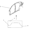
Fig. 1 is the decomposition view according to sidewall of the present invention;
Fig. 2 is the molding tool that uses in the method according to the invention, has first and second profiled members that are used to make first plastic housing;
Fig. 3 is the molding tool that uses in the method according to the invention, has third and fourth profiled member that is used to make second plastic housing;
Fig. 4 uses molding tool in the method according to the invention, and this molding tool has the 3rd profiled member shown in Figure 3 and is used for the 5th profiled member to the second plastic housing coating;
Fig. 5 is the molding tool that uses in the method according to the invention, and this molding tool has first mould shown in Figure 2 and the 5th mould shown in Figure 4, so that first and second plastic housings are connected with the metal structure that is arranged between the said plastic housing.
The specific embodiment
At first wanting clear and definite is; In described each form of implementation; For identical parts use identical Reference numeral or identical assembly mark; Wherein, the disclosure that is included in the whole specification also can be transferred on the same parts with same reference numerals or same components mark according to its meaning.Selected position description in specification, also relevant like top, below, side etc. with direct description and the accompanying drawing that illustrates, and when change in location, also be transformed on reposition according to its meaning.These accompanying drawings of comprehensive description in addition.
According to Fig. 1, have two plastic housings 2,3 and the metal structure 4 between said plastic housing 2 and 3 by sidewall 1 of the present invention.The thermoplastic that plastic housing 2 and 3 is preferably strengthened by continuous fiber is processed.Metal structure 4 for example can be designed as the steelframe that is made up of the section bar of bending and less plate.Certainly, metal structure 4 also can be processed by aluminium or other appropriate metal or alloy.
As shown in Figure 2, according to by method of the present invention, by means of the moulding of first profiled member 5 with second profiled member, 6 realizations, first plastic housing 2 of molding tool.For this reason, can heat the plastics of inserting in the molding tool, the thermoplastic strengthened of continuous fiber preferably, and said when prior art being discussed like beginning, place desirable shape through closed two profiled members 5,6.Then can stipulate last cooling stage.This forming process is a large amount of known to those skilled in the art, therefore no longer this process is done further describing at this.
Fig. 3 shows the manufacturing of second plastic housing 3.By means of the moulding of third and fourth profiled member, 7,8 realizations, second plastic housing 3, wherein, the forming process of second plastic housing 3 is corresponding with the forming process of first plastic housing 2.
According to Fig. 4, the coating 9 of for example plastic foam form is incorporated in the 5th profiled member 10.The 4th profiled member 8 is removed, and second plastic housing 3 is retained on the 3rd profiled member 7.Through the 3rd profiled member 7 and the 5th profiled member 10 are engaged, second plastic housing 3 is connected with coating 9.It should be noted that at this coating 9 also can be injected in the cavity that is formed between the 5th profiled member 10 and second plastic housing 3 behind the 3rd profiled member 7 and the 5th profiled member 10 joints.Coating 9 preferably also has outside cover layer, particularly top coat layer.Cover layer for example can form through the colorful film of inserting in the 5th profiled member 10, and wherein, the cavity between second plastic housing 3 and colorful film can be used above-mentioned plastic foam, for example the PU-foam jet.
As being found out by Fig. 5, after forming process finished, the 3rd profiled member 7 was removed from second plastic housing 3, and wherein, second plastic housing 3 is retained on the 5th profiled member 10.Then, the metal structure 4 and second plastic housing 3 are bonded together.And metal structure 4 same with engaging of first profiled member 5 and plastic housing 3 are bonded to sidewall 1 to first plastic housing 2 that after removing second profiled member 6, also is arranged in first profiled member 5 through the 5th profiled member 10 in coated with adhesive layers 11 backs.
What must explain at last is advantageously to use each core as the first and the 3rd profiled member 5,7, and use each mould as the second, the 4th and the 5th profiled member 6,8,10.The permanent mould that can profiled member 6,8,10 is configured to be made from aluminum or steel in addition.Yet, also can advantageously use be clamped in the metal frame and can load compressed-air actuated pressure film as second profiled member 6.
List of numerals:
1 sidewall
2 plastic housings
3 plastic housings
4 metal structures
5 first profiled members
6 second profiled members
7 the 3rd profiled members
8 the 4th profiled members
9 coatings
10 the 5th profiled members
11 adhesive phases
Claims (9)
1. one kind is passed through to use at least one molding tool to make the method for the sidewall (1) of body of a motor car; It is characterized in that; Said sidewall (1) is made up of two plastic housings (2,3) and the reinforcement metal structure (4) between said plastic housing; Wherein, Realize the moulding of first plastic housings (2) by means of first and second profiled members (5,6), and realize the moulding of second plastic housing (3) coating (9) being incorporated in the 5th profiled member (10) by means of third and fourth profiled member (7,8); Wherein, The 4th profiled member (8) is removed, and said second plastic housing (3) is retained in that the 3rd profiled member (7) is gone up and through engaging with the 5th profiled member (10) and being connected with said coating (9), said the 3rd profiled member (7) is removed from said second plastic housing (3); Wherein, Said second plastic housing (3) is retained in that said the 5th profiled member (10) is gone up and with said metal structure (4) and said second plastic housing (3) bonding, and then, joint through said the 5th profiled member (10) and said first profiled member (5) and said metal structure (4) and said second plastic housing (3) bond together afterwards at coated with adhesive layer (11) removing said first plastic housing (2) that said second profiled member (6) also is positioned at said first profiled member (5) afterwards.
2. method according to claim 1 is characterized in that, said coating (9) has outside cover layer, especially top coat layer, and is applied in said the 5th profiled member (10).
3. method according to claim 2 is characterized in that, after said cover layer was applied to said the 5th profiled member (10), with plastic foam, especially the PU-foam jet was in said the 5th profiled member (10).
4. according to the described method of one of claim 1 to 3, it is characterized in that each thermoplastic of being strengthened by continuous fiber of said first and second plastic housings (2,3) constitutes.
5. according to the described method of one of claim 1 to 4, it is characterized in that, use each core, and use each mould as the second, the 4th and the 5th profiled member (6,8,10) as the first and the 3rd profiled member (5,7).
6. method according to claim 5 is characterized in that, uses the permanent mould that is made from aluminum or steel as said the second, the 4th and the 5th profiled member (6,8,10).
7. according to claim 5 or 6 described methods, it is characterized in that the working pressure film is as second profiled member (6).
8. a sidewall (1) that is used for body of a motor car is characterized in that, this sidewall is according to constituting like described method manufacturing one of in the claim 1 to 6 and by two plastic housings (2,3) and metal structure (4) between said plastic housing, inner.
9. sidewall according to claim 7 is characterized in that, said plastic housing (2,3) is made up of the thermoplastic that continuous fiber is strengthened respectively.
Applications Claiming Priority (2)
| Application Number | Priority Date | Filing Date | Title |
|---|---|---|---|
| DE102010052377 | 2010-11-24 | ||
| DE102010052377.1 | 2010-11-24 |
Publications (2)
| Publication Number | Publication Date |
|---|---|
| CN102582012A true CN102582012A (en) | 2012-07-18 |
| CN102582012B CN102582012B (en) | 2015-01-21 |
Family
ID=44992782
Family Applications (1)
| Application Number | Title | Priority Date | Filing Date |
|---|---|---|---|
| CN201110463267.0A Active CN102582012B (en) | 2010-11-24 | 2011-11-24 | Method for manufacturing side wall |
Country Status (2)
| Country | Link |
|---|---|
| EP (1) | EP2457808B1 (en) |
| CN (1) | CN102582012B (en) |
Cited By (1)
| Publication number | Priority date | Publication date | Assignee | Title |
|---|---|---|---|---|
| CN105339244A (en) * | 2013-06-12 | 2016-02-17 | 蒂森克虏伯钢铁欧洲股份公司 | Side wall group for passenger vehicles |
Families Citing this family (3)
| Publication number | Priority date | Publication date | Assignee | Title |
|---|---|---|---|---|
| DE102013214782A1 (en) * | 2013-07-29 | 2015-01-29 | Bayerische Motoren Werke Aktiengesellschaft | Vehicle body with two glued body components |
| DE102015014643A1 (en) * | 2015-11-12 | 2017-05-18 | GM Global Technology Operations LLC (n. d. Ges. d. Staates Delaware) | Automotive body |
| JP6700122B2 (en) * | 2016-06-30 | 2020-05-27 | 株式会社Subaru | Side sill structure made of fiber reinforced resin |
Citations (5)
| Publication number | Priority date | Publication date | Assignee | Title |
|---|---|---|---|---|
| AU2949771A (en) * | 1970-06-01 | 1972-12-07 | Pressed Steel Fisher Limited | Vehicle bodies of plastics material |
| EP0039071A2 (en) * | 1980-04-28 | 1981-11-04 | Aktiengesellschaft Adolph Saurer | Body, especially for motor vehicles |
| US5512233A (en) * | 1994-10-26 | 1996-04-30 | Davidson Textron Inc. | Method of making a panel with a spray formed skin |
| US5738747A (en) * | 1994-12-19 | 1998-04-14 | Roamer Corporation | Method of manufacturing a recreational vehicle cabin |
| CN201494000U (en) * | 2009-07-24 | 2010-06-02 | 应革 | Die for fabricating shell of vehicle body |
Family Cites Families (1)
| Publication number | Priority date | Publication date | Assignee | Title |
|---|---|---|---|---|
| DE102007024530A1 (en) | 2007-05-24 | 2008-11-27 | Novem Car Interior Design Gmbh | Compression molding method for manufacturing compression part, particularly decorative part and covering part for vehicle interior, involves inserting and positioning material of decorative layer, and plastic molded material forms carrier |
-
2011
- 2011-11-18 EP EP11189718.7A patent/EP2457808B1/en not_active Not-in-force
- 2011-11-24 CN CN201110463267.0A patent/CN102582012B/en active Active
Patent Citations (5)
| Publication number | Priority date | Publication date | Assignee | Title |
|---|---|---|---|---|
| AU2949771A (en) * | 1970-06-01 | 1972-12-07 | Pressed Steel Fisher Limited | Vehicle bodies of plastics material |
| EP0039071A2 (en) * | 1980-04-28 | 1981-11-04 | Aktiengesellschaft Adolph Saurer | Body, especially for motor vehicles |
| US5512233A (en) * | 1994-10-26 | 1996-04-30 | Davidson Textron Inc. | Method of making a panel with a spray formed skin |
| US5738747A (en) * | 1994-12-19 | 1998-04-14 | Roamer Corporation | Method of manufacturing a recreational vehicle cabin |
| CN201494000U (en) * | 2009-07-24 | 2010-06-02 | 应革 | Die for fabricating shell of vehicle body |
Cited By (2)
| Publication number | Priority date | Publication date | Assignee | Title |
|---|---|---|---|---|
| CN105339244A (en) * | 2013-06-12 | 2016-02-17 | 蒂森克虏伯钢铁欧洲股份公司 | Side wall group for passenger vehicles |
| CN105339244B (en) * | 2013-06-12 | 2018-07-24 | 蒂森克虏伯钢铁欧洲股份公司 | The side wall assemblies of car |
Also Published As
| Publication number | Publication date |
|---|---|
| EP2457808B1 (en) | 2014-04-30 |
| CN102582012B (en) | 2015-01-21 |
| EP2457808A1 (en) | 2012-05-30 |
Similar Documents
| Publication | Publication Date | Title |
|---|---|---|
| EP2678148B1 (en) | Process for manufacturing composite material products, as well as products manufactured with this process | |
| JP4914213B2 (en) | Manufacturing method of composite trim parts for automobile interior | |
| US7972129B2 (en) | Compound tooling system for molding applications | |
| EP2683535B1 (en) | Process and system for manufacturing composite material products | |
| EP1885547B1 (en) | Process for the production of a laminated composite product | |
| JP2009534235A (en) | Method for manufacturing a composite structure | |
| CN104454855A (en) | Composite material/metal trapezoidal tooth mixing and connecting structure and preparation method thereof | |
| CN102582012A (en) | Method for manufacturing side wall | |
| EP3342573B1 (en) | Method and apparatus for producing a trim component having a molded rim at an edge thereof | |
| CN102562724B (en) | For the force transfer element of FKV parts | |
| CN110370679B (en) | Automobile back door inner plate and preparation method thereof | |
| US20050279152A1 (en) | Deforming tool and process for manufacturing thereof | |
| CN112720996A (en) | Compression molding method for ornament on tail door | |
| CN101450521A (en) | Forming device and method of in-mold decoration | |
| KR101972021B1 (en) | Composite panel for automotive interior part with double bond structure | |
| CN110682550B (en) | Vehicle door or tailgate with support structure and method for producing the same | |
| JP6188559B2 (en) | Manufacturing method of vehicle ceiling material and heating press mold used therefor | |
| CN201296014Y (en) | A forming device of in-mold decorations | |
| CN112536945B (en) | Forming processing die and forming processing method for carbon fiber parts | |
| JP2005526638A (en) | Method for coating a component made of fiber reinforced plastic and component formed by the method | |
| KR100248786B1 (en) | Mold for vacuum casting and its manufacturing method | |
| JP3028232B1 (en) | Molding method for glass fiber reinforced plastic used in closed system molding method of glass fiber reinforced plastic and method for producing the same | |
| KR100795390B1 (en) | Box type hollow structure made of frp with overlap construction for vehicle and manufacturing method thereof | |
| GB2443941A (en) | Moulded connecting structure | |
| CN102874238A (en) | Automobile hand-brake handle sheath, production method thereof and special device used in production method |
Legal Events
| Date | Code | Title | Description |
|---|---|---|---|
| C06 | Publication | ||
| PB01 | Publication | ||
| C10 | Entry into substantive examination | ||
| SE01 | Entry into force of request for substantive examination | ||
| C14 | Grant of patent or utility model | ||
| GR01 | Patent grant | ||
| CP01 | Change in the name or title of a patent holder | ||
| CP01 | Change in the name or title of a patent holder |
Address after: Graz, Austria Patentee after: Magna Steyr Automotive Technologies Address before: Graz, Austria Patentee before: MAGNA STEYR FAHRZEUGTECHNIK AG & CO KG |