CN102554340A - Automatic rotary cutting feeder for gearbox shaft - Google Patents
Automatic rotary cutting feeder for gearbox shaft Download PDFInfo
- Publication number
- CN102554340A CN102554340A CN2012100289737A CN201210028973A CN102554340A CN 102554340 A CN102554340 A CN 102554340A CN 2012100289737 A CN2012100289737 A CN 2012100289737A CN 201210028973 A CN201210028973 A CN 201210028973A CN 102554340 A CN102554340 A CN 102554340A
- Authority
- CN
- China
- Prior art keywords
- support
- supporting material
- material roller
- cylinder
- cutter
- Prior art date
- Legal status (The legal status is an assumption and is not a legal conclusion. Google has not performed a legal analysis and makes no representation as to the accuracy of the status listed.)
- Granted
Links
Images


Abstract
The invention discloses an automatic rotary cutting feeder for a gearbox shaft, which comprises a machine tool body, a transfer propelling mechanism, a supporting roller component, a rotary cutter mechanism, a stopping mechanism and a PLC (programmable logic controller). A workpiece 3 is propelled onto a rotary supporting roller surface in the supporting roller component by the transfer propelling mechanism comprising a roller seat and a propelling device which are mounted on a feeding support, and the workpiece 3 is stopped and positioned by the stopping mechanism and cut by the rotary cutter mechanism. Cutting precision and production efficiency of the gearbox shaft are improved, cutting efficiency is high, labor intensity is low, and automated production of the gearbox shaft is realized.
Description
Technical field:
The present invention relates to a kind of gear-box axle and rotate the cutting stock machine automatically.
Background technology:
Gear-box axle is the driving parts in the gearbox, and what the axle rapidoprint adopted mostly is bar (round steel) processing, and first working procedure is a cutting stock.Improve cutting efficiency and improve the processing mode of gear-box axle cutting stock, be the emphasis that industry processing is paid close attention to all the time.And be methods such as sawing machine sawing, emery wheel cutting mostly for gear-box axle cutting stock method at present.These cutting methods are because of artificial single-piece is cut, bar (round steel) is fixed the factor that modes such as can not rotating cutting stock is operated, and ubiquity the shortcoming that cutting efficiency is low, labour intensity is big, causes its application in gear-box axle production to be restricted.
Summary of the invention
The object of the present invention is to provide the gear-box axle that a kind of cutting efficiency is high, labour intensity is low to rotate the cutting stock machine automatically.
Its technical scheme is: a kind of gear-box axle rotates the cutting stock machine automatically, it is characterized in that: be made up of bed piece, handover propulsive mechanism, supporting material roller assembly, rotary cutter mechanism, stock stop and PLC;
Bed piece is by sending pusher support, supporting material roller support and cutter support three pack supports to constitute, and three pack supports are the plane frame that is welded to form; Wherein, send pusher support 2 to be step plane frame, its pusher support on one side is higher than feeding support on one side, and the plane is the flat board of twice elongated slot before and after being provided with on the pusher support on one side;
Transferring propulsive mechanism send the roller mount on one side of stock support in the pusher support to send the propulsion plant on one side of pusher support in the pusher support to form with being installed in by being installed in; Wherein, Roller mount is regulated bolt, slider support, roller and the second adjusting bolt by lower shoe, turning rolls, first and is constituted; Two relative turning rolls are installed on the base plate at interval; Be respectively equipped with the roller shaft that is connected with roller on the turning rolls, be arranged on first on the turning rolls and regulate bolt and slide block butt by slider support; Regulate through second respectively on the stock support plane on one side two groups of roller mount are installed about bolt; Propulsion plant is configured to by feeding motor, reduction box, screw mandrel connection seat, screw mandrel, cylinder and cylinder; Transfer cylinder frame by two transverse slats and riser of avris constitute the shaped as frame structure up and down; The line slideway that is provided with on the previous elongated slot both sides of offering on the flat board is passed in the lower end of its riser; Stretch out bottom, transfer the cylinder piston rod end of fixing on the upper cross plate of cylinder frame and be connected with upper holder block, be connected with down back-up block on the lower cross plate of handover cylinder frame at flat board; Following back-up block passes a back elongated slot of offering on the flat board, and is corresponding with upper holder block; Feeding motor, reduction box, screw mandrel connection seat, screw mandrel be installed on successively dull and stereotyped below, the nut that is threaded on the screw mandrel with transfer cylinder frame and link;
The supporting material roller assembly is made up of last supporting material roller, time supporting material roller, last supporting material roller gear, following supporting material roller gear, idler gear, idler gear belt pulley, V belt, reduction box belt pulley, reduction box, supporting material roller motor; The two ends of upper and lower supporting material roller activity respectively are connected on the supporting material roller support; A pusher support end on one side stretches out the supporting material roller support in pusher support near sending for it; Be separately installed with upper and lower supporting material roller gear; These two gears all mesh with idler gear; Idler gear is supported by the gear shaft that connects on the bearing that is installed on the supporting material roller support, and the supporting material roller motor is connected with belt wheel through reduction box, and belt wheel is connected with the coaxial mounted counter wheel of idler gear through belt;
Rotary cutter mechanism is made up of base plate, line slideway, propulsion cylinder and knife assembly, and the two ends of the knife bar in the knife assembly are connected in respectively in the left and right rotary sleeve and by gland and compress; Left-handed pivoted housing is connected and fixed on left support abutment through rolling bearing, plane bearing, end cap and nut; The dextrorotation pivoted housing stretches out right support abutment and connects with the cutter motor output shaft through reduction box; The outer rim of knife bar is provided with by the fastening spacer of nut, is provided with cutter 11-11 according to adding the required intervals of lengths of labor and materials on the knife bar; Workpiece on knife assembly and the upper and lower supporting material roller roll surface is 45 degree angles and tilts to install; Its left and right bearing is fixed on the plane of base plate one end; The both sides of base plate connect the straight line guide rail respectively, and the one side of line slideway is fixed on the cutter support, and the another side activity is connected on the base plate; The other end plane of base plate connects with the piston rod of propulsion cylinder, and propulsion cylinder is fixedly linked on the lathe bed of cutter support;
Stock stop is made up of backgauge cylinder, backgauge cylinder block, striker plate, and the backgauge cylinder is fixed by the backgauge cylinder block that is installed on supporting material roller support one side, and the tailpiece of the piston rod of backgauge cylinder is connected with striker plate.
The below of said knife assembly is provided with and extends in the outer shedding mechanism that is made up of stripper, charging basket of cutter support.
The required cooling fluid of said cutter cut workpiece outputs to the mouth spray that is installed in cutter support below by the liquid reserve tank that is installed on the lathe bed lower position through magnetic valve, infusion pump and feed tube; Cooling fluid after the injection is pooled to liquid back pipe through the return tray that is arranged on cutter support below, is back to liquid reserve tank after filtering again.
Its technique effect is: the present invention rotates the processing mode of cutting simultaneously with multiplex's part; And by the setting of programmable PLC formula, self-feeding automatic material clamping, automatic sawing, cutting, the Automatic Cycle work that goes round and begins again; The precision and the production efficiency of gear-box axle cutting processing have been improved; Cutting efficiency is high, labour intensity is low, has realized the gear-box axle automated production.
Description of drawings:
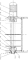
Fig. 1 is an overall structure sketch map of the present invention;
Fig. 2 is the plane of Fig. 1;
Fig. 3 is that the A of Fig. 1 is to view;
Fig. 4 is the knife assembly structural representation;
Fig. 5 is a supporting material roller assembly floor map;
Fig. 6 is that the B of Fig. 5 is to view;
Fig. 7 is the A-A profile of Fig. 2;
Fig. 8 is a roller mount facade structures sketch map;
Fig. 9 is a rotation cutting stock schematic diagram.
The specific embodiment
Shown in Fig. 1-9, a kind of gear-box axle rotates the cutting stock machine automatically, is made up of bed piece, handover propulsive mechanism, supporting material roller assembly, rotary cutter mechanism, stock stop and PLC.
Bed piece is by sending pusher support 2, supporting material roller support 26 and cutter support 16 3 pack supports to constitute, and three pack supports are the plane frame that is welded.Wherein, send pusher support 2 to be step plane frame, its pusher support on one side is higher than feeding support on one side, and the plane is the flat board 4 of twice elongated slot before and after being provided with on the pusher support on one side.
Transferring propulsive mechanism send the roller mount 1 on one side of stock support in the pusher support 2 to send the propulsion plant on one side of pusher support in the pusher support 2 to form with being installed in by being installed in.Wherein, Roller mount 1 (see figure 8) is regulated bolt, slider support, roller and the second adjusting bolt by lower shoe, turning rolls, first and is constituted; Base plate 1-1 goes up two relative turning rolls 1-2 is installed at interval; Be respectively equipped with the roller shaft that is connected with roller 1-5 that supports by slide block 1-4 on the turning rolls, be arranged on first on the turning rolls and regulate bolt 1-3 and slide block butt; Regulate through second respectively on the stock support plane on one side two groups of roller mount are installed about bolt 1-6.Regulate the adjusting bolt 1 on the rolling wheel support, that accomplishes two pair roller faces on the fixing feeding roller moves the radiai adjustment of the x direction of completion idler wheel surface in opposite directions.Simultaneously, regulate the adjusting bolt 2 of base plate, accomplish the adjusting of the y short transverse of idler wheel surface.Propulsion plant is configured to by feeding motor, reduction box, screw mandrel connection seat, screw mandrel, cylinder and cylinder; Transfer cylinder frame 9-2 by two transverse slats and riser of avris constitute the shaped as frame structure up and down; The line slideway 9-3 that is provided with on the previous elongated slot both sides of offering on dull and stereotyped 4 is passed in the lower end of its riser; Stretch out bottom, transfer the cylinder 9-5 tailpiece of the piston rod of fixing on the upper cross plate of cylinder frame and be connected with upper holder block 9-4, be connected with down back-up block 9-1 on the lower cross plate of handover cylinder frame at flat board; Following back-up block passes a back elongated slot of offering on the flat board, and is corresponding with upper holder block; Feeding motor 5, reduction box 6, screw mandrel connection seat 7, screw mandrel 8 be installed on successively dull and stereotyped 4 below, the nut that is threaded on the screw mandrel with transfer cylinder frame 9-2 and link.Transfer the forward-reverse action of cylinder frame, accomplish by feeding motor 5.Its handover speed, transmitting place of transferring cylinder frame is adjusted by the PLC that is installed on the lathe bed, and the position is accurate, stable action.
Supporting material roller assembly (see figure 5) is made up of last supporting material roller, time supporting material roller, last supporting material roller gear, following supporting material roller gear, idler gear, idler gear belt pulley, V belt, reduction box belt pulley, reduction box, supporting material roller motor; The two ends of upper and lower supporting material roller 27,28 activity respectively are connected on the supporting material roller support 26; A pusher support end on one side stretches out the supporting material roller support in pusher support 2 near sending for it; Be separately installed with upper and lower supporting material roller gear 24,25; These two gears all mesh with idler gear 29; Idler gear is supported by the gear shaft that connects on the bearing that is installed on the supporting material roller support, and supporting material roller motor 19 is connected with belt wheel 21 through reduction box 20, and belt wheel is connected with the coaxial mounted counter wheel 23 of idler gear through belt 22; Upper and lower supporting material roller 27,28 is measure-alike.The rotation of upper and lower supporting material roller is meshed two supporting material roller gears simultaneously by idler gear and is accomplished.Its rotary speed is controlled by supporting material roller motor that is installed in support and the PLC that is installed on the lathe bed, reaches the adjusting of rotating speed.
Rotary cutter mechanism (see figure 4) is made up of base plate, line slideway, propulsion cylinder and knife assembly, and the two ends of the knife bar 11-9 in the knife assembly 11 are connected in respectively in left and right rotary sleeve 11-6, the 11-12 and by gland 11-7 and compress; Left-handed pivoted housing is connected and fixed on left support abutment 11-5 through rolling bearing 11-4, plane bearing 11-3, end cap 11-2 and nut 11-1; The dextrorotation pivoted housing stretches out right support abutment 11-13 and connects with cutter motor 11-15 output shaft through reduction box 11-14; The outer rim of knife bar 11-9 is provided with the fastening spacer 11-10 by nut 11-8, is provided with cutter 11-11 according to adding the required intervals of lengths of labor and materials on the knife bar.Workpiece 3 on knife assembly and the upper and lower supporting material roller roll surface is 45 degree angles and tilts to install (see figure 3); Its left and right bearing is fixed on the plane of base plate 14 1 ends; The both sides of base plate connect straight line guide rail 15 respectively; The one side of line slideway is fixed on the cutter support 16, and the another side activity is connected on the base plate; The other end plane of base plate connects with the piston rod of propulsion cylinder, and propulsion cylinder is fixedly linked on the lathe bed of cutter support.
The stock stop (see figure 3) is made up of backgauge cylinder, backgauge cylinder block, striker plate, and backgauge cylinder 12 is fixing by the backgauge cylinder block that is installed on supporting material roller support one side 13, and the tailpiece of the piston rod of backgauge cylinder connects striker plate 13-1.
The below of said knife assembly 11 is provided with and extends in the outer shedding mechanism (Fig. 3) that is made up of stripper 17, charging basket 18 of cutter support 16.
The required cooling fluid 30-2 of said cutter 11-11 cut workpiece outputs to the mouth spray 30-7 (Fig. 1,2,3) that is installed in cutter support 16 belows by the liquid reserve tank 30-1 that is installed on the lathe bed lower position through magnetic valve 30-3, infusion pump 30-4 and feed tube 30-5; Cooling fluid after the injection is pooled to liquid back pipe 30-6 through the return tray 30-8 that is arranged on cutter support below, is back to liquid reserve tank after filtering again.
Its course of work: the mechanism that workpiece 3 is established by other is transported to and send on the pusher support 2; Regulating following back-up block 9-1 and the excircle of workpiece of transferring cylinder frame 9-2 offsets; The upper holder block 9-4 that transfers cylinder frame drives that upper holder block is pushed down and with back-up block workpiece pressing cylindrical down under the effect of transferring cylinder 9-5 piston rod.Feeding motor 5 is opened power supply; Through reduction box 6 and screw mandrel connection seat 7, drive screw mandrel 8 rotations, the feed screw nut who connects with the handover cylinder frame; Rotation with screw mandrel promotes to transfer cylinder frame along the elongated slot direction displacement of offering on dull and stereotyped 4; Workpiece is advanced on the retainer roll surface position of rotation, supporting material roller motor 19 rotates through reduction box 20, belt wheel, belt, drive idler gear 29, and is engaged to supporting material roller gear 24, following supporting material roller gear 25 simultaneously; About making, supporting material roller 27,28 does rotation in the same way; When workpiece was advanced to the upper and lower retainer roll surface of rotation continuously through transferring propulsive mechanism, cutter motor 11-15 drove left and right rotary sleeve 11-6,11-12 and cutter 11-11 rotation through the rotation of reduction box 11-14 output shaft; When workpiece was advanced to cutting work station, the piston rod of backgauge cylinder 12 advanced striker plate 13-1, and the workpiece that makes propelling is transferred the cylinder frame back resetting by the axial backgauge of striker plate location; Simultaneously, the propulsion cylinder piston rod promotes base plate 14 and advances, and the cutter incision workpiece of rotation drives tightly workpiece rotation and cutting in the position, upper and lower retainer roll surface therebetween angle synchronously, the backhaul of backgauge cylinder piston rod, and striker plate resets; The gear-box axle spare that cuts down falls into charging basket 18 automatically by discharging swash plate 17 and concentrates the placement back to change next procedure processing, and the backhaul of propulsion cylinder piston rod drives base plate and returns, the cutting of entering next round.
Claims (3)
1. a gear-box axle rotates the cutting stock machine automatically, it is characterized in that: be made up of bed piece, handover propulsive mechanism, supporting material roller assembly, rotary cutter mechanism, stock stop and PLC;
Bed piece is by sending pusher support (2), supporting material roller support (26) and cutter support (16) three pack supports to constitute, and three pack supports are the plane frame that is welded to form; Wherein, sending the pusher support is step plane frame, and its pusher support on one side is higher than feeding support on one side, and the plane is the flat board (4) of twice elongated slot before and after being provided with on the pusher support on one side;
Transferring propulsive mechanism send the roller mount on one side of stock support in the pusher support to send the propulsion plant on one side of pusher support in the pusher support to form with being installed in by being installed in; Wherein, Roller mount (1) is regulated bolt, slider support, roller and the second adjusting bolt by lower shoe, turning rolls, first and is constituted; Base plate (1-1) is gone up two relative turning rolls (1-2) is installed at interval; Be respectively equipped with the roller shaft that is connected with roller (1-5) that supports by slide block (1-4) on the turning rolls, be arranged on first on the turning rolls and regulate bolt (1-3) and slide block butt; Regulate through second respectively on the stock support plane on one side two groups of roller mount are installed about bolt (1-6); Propulsion plant is configured to by feeding motor, reduction box, screw mandrel connection seat, screw mandrel, cylinder and cylinder; Transfer cylinder frame (9-2) by two transverse slats and riser of avris constitute the shaped as frame structure up and down; The line slideway (9-3) that is provided with on the previous elongated slot both sides of offering on the flat board (4) is passed in the lower end of its riser; Stretch out bottom, transfer cylinder (9-5) tailpiece of the piston rod of fixing on the upper cross plate of cylinder frame and be connected with upper holder block (9-4), be connected with down back-up block (9-1) on the lower cross plate of handover cylinder frame at flat board; Following back-up block passes a back elongated slot of offering on the flat board, and is corresponding with upper holder block; Feeding motor (5), reduction box (6), screw mandrel connection seat (7), screw mandrel (8) be installed on successively dull and stereotyped below, the nut that is threaded on the screw mandrel with transfer cylinder frame (9-2) and link;
The supporting material roller assembly is made up of last supporting material roller, time supporting material roller, last supporting material roller gear, following supporting material roller gear, idler gear, idler gear belt pulley, V belt, reduction box belt pulley, reduction box, supporting material roller motor; The two ends of upper and lower supporting material roller (27,28) activity respectively are connected on the supporting material roller support (26); A pusher support end on one side stretches out the supporting material roller support in pusher support near sending for it; Be separately installed with upper and lower supporting material roller gear (24,25); These two gears all mesh with idler gear (29); Idler gear is supported by the gear shaft that connects on the bearing that is installed on the supporting material roller support, and supporting material roller motor (19) is connected with belt wheel (21) through reduction box (20), and belt wheel is connected with the coaxial mounted counter wheel of idler gear (23) through belt (22); Upper and lower supporting material roller 27,28 is measure-alike.
Rotary cutter mechanism is made up of base plate, line slideway, propulsion cylinder and knife assembly, and the two ends of the knife bar (11-9) in the knife assembly (11) are connected in respectively in the left and right rotary sleeve (11-6,11-12) and by gland (11-7) and compress; Left-handed pivoted housing is connected and fixed on left support abutment (11-5) through rolling bearing (11-4), plane bearing (11-3), end cap (11-2) and nut (11-1); The dextrorotation pivoted housing stretches out right support abutment (11-13) and connects with cutter motor (11-15) output shaft through reduction box (11-14); The outer rim of knife bar is provided with by the fastening spacer (11-10) of nut (11-8), is provided with cutter (11-11) according to adding the required intervals of lengths of labor and materials on the knife bar; Workpiece (3) on knife assembly and the upper and lower supporting material roller roll surface is 45 degree angles and tilts to install; Its left and right bearing is fixed on the plane of base plate (14) one ends; The both sides of base plate connect straight line guide rail (15) respectively; The one side of line slideway is fixed on the cutter support (16), and the another side activity is connected on the base plate; The other end plane of base plate connects with the piston rod of propulsion cylinder, and propulsion cylinder is fixedly linked on the lathe bed of cutter support;
Stock stop is made up of backgauge cylinder, backgauge cylinder block, striker plate, and backgauge cylinder (12) is fixing by the backgauge cylinder block (13) that is installed on supporting material roller support one side, and the tailpiece of the piston rod of backgauge cylinder is connected with striker plate (13-1).
2. gear-box axle according to claim 1 rotates the cutting stock machine automatically, it is characterized in that: the below of said knife assembly (11) is provided with and extends in the outer shedding mechanism by discharging swash plate (17) and charging basket (18) formation of cutter support (16).
3. gear-box axle according to claim 1 rotates the cutting stock machine automatically; It is characterized in that: the required cooling fluid (30-2) of said cutter (11-11) cut workpiece outputs to the mouth spray (30-7) that is installed in cutter support (16) below by the liquid reserve tank that is installed on the lathe bed lower position (30-1) through magnetic valve (30-3), infusion pump (30-4) and feed tube (30-5); Cooling fluid after the injection is pooled to liquid back pipe (30-6) through the return tray (30-8) that is arranged on cutter support below, is back to liquid reserve tank after filtering again.
Priority Applications (1)
| Application Number | Priority Date | Filing Date | Title |
|---|---|---|---|
| CN 201210028973 CN102554340B (en) | 2012-02-10 | 2012-02-10 | Automatic rotary cutting feeder for gearbox shaft |
Applications Claiming Priority (1)
| Application Number | Priority Date | Filing Date | Title |
|---|---|---|---|
| CN 201210028973 CN102554340B (en) | 2012-02-10 | 2012-02-10 | Automatic rotary cutting feeder for gearbox shaft |
Publications (2)
| Publication Number | Publication Date |
|---|---|
| CN102554340A true CN102554340A (en) | 2012-07-11 |
| CN102554340B CN102554340B (en) | 2013-08-07 |
Family
ID=46401694
Family Applications (1)
| Application Number | Title | Priority Date | Filing Date |
|---|---|---|---|
| CN 201210028973 Active CN102554340B (en) | 2012-02-10 | 2012-02-10 | Automatic rotary cutting feeder for gearbox shaft |
Country Status (1)
| Country | Link |
|---|---|
| CN (1) | CN102554340B (en) |
Cited By (5)
| Publication number | Priority date | Publication date | Assignee | Title |
|---|---|---|---|---|
| CN102825334A (en) * | 2012-09-13 | 2012-12-19 | 江苏省南扬机械制造有限公司 | Automatic cutting saw |
| CN103708265A (en) * | 2013-11-21 | 2014-04-09 | 南通凯迪自动机械有限公司 | Servo-controlled cutter swinging device |
| CN105033350A (en) * | 2015-07-30 | 2015-11-11 | 天津市帝标建材有限公司 | Aluminum veneer cutting equipment |
| CN106001750A (en) * | 2016-07-31 | 2016-10-12 | 丁皇刚 | Robot achieving optical shaft fixed-length cutting and classifying packaging |
| CN108580792A (en) * | 2018-06-04 | 2018-09-28 | 浙江程达锻件有限公司 | A kind of iron staff cutter device easy to use |
Citations (5)
| Publication number | Priority date | Publication date | Assignee | Title |
|---|---|---|---|---|
| EP0791424A2 (en) * | 1996-02-13 | 1997-08-27 | Pietro Lattanzi | Tubular sawing system for making holes in or cutting out cores from concrete walls or walls made of concrete blocks |
| US20020174913A1 (en) * | 2001-04-23 | 2002-11-28 | Mats Johansson | Cutting tool unit and assembly, and machine and associated cutting method |
| JP2011131352A (en) * | 2009-12-25 | 2011-07-07 | Mitsuboshi Belting Ltd | Device and method for automatically cutting cylindrical body |
| CN102337383A (en) * | 2011-10-09 | 2012-02-01 | 安徽明雁齿轮有限公司 | High-frequency automatic quenching machine for reverse gear shafts of transmission cases |
| CN202461675U (en) * | 2012-02-10 | 2012-10-03 | 安徽明雁齿轮有限公司 | Automatic rotation cutting feeding machine for gearbox shafts |
-
2012
- 2012-02-10 CN CN 201210028973 patent/CN102554340B/en active Active
Patent Citations (5)
| Publication number | Priority date | Publication date | Assignee | Title |
|---|---|---|---|---|
| EP0791424A2 (en) * | 1996-02-13 | 1997-08-27 | Pietro Lattanzi | Tubular sawing system for making holes in or cutting out cores from concrete walls or walls made of concrete blocks |
| US20020174913A1 (en) * | 2001-04-23 | 2002-11-28 | Mats Johansson | Cutting tool unit and assembly, and machine and associated cutting method |
| JP2011131352A (en) * | 2009-12-25 | 2011-07-07 | Mitsuboshi Belting Ltd | Device and method for automatically cutting cylindrical body |
| CN102337383A (en) * | 2011-10-09 | 2012-02-01 | 安徽明雁齿轮有限公司 | High-frequency automatic quenching machine for reverse gear shafts of transmission cases |
| CN202461675U (en) * | 2012-02-10 | 2012-10-03 | 安徽明雁齿轮有限公司 | Automatic rotation cutting feeding machine for gearbox shafts |
Cited By (7)
| Publication number | Priority date | Publication date | Assignee | Title |
|---|---|---|---|---|
| CN102825334A (en) * | 2012-09-13 | 2012-12-19 | 江苏省南扬机械制造有限公司 | Automatic cutting saw |
| CN102825334B (en) * | 2012-09-13 | 2014-04-02 | 江苏省南扬机械制造有限公司 | Automatic cutting saw |
| CN103708265A (en) * | 2013-11-21 | 2014-04-09 | 南通凯迪自动机械有限公司 | Servo-controlled cutter swinging device |
| CN103708265B (en) * | 2013-11-21 | 2015-12-02 | 南通凯迪自动机械有限公司 | Servo flail mechanism |
| CN105033350A (en) * | 2015-07-30 | 2015-11-11 | 天津市帝标建材有限公司 | Aluminum veneer cutting equipment |
| CN106001750A (en) * | 2016-07-31 | 2016-10-12 | 丁皇刚 | Robot achieving optical shaft fixed-length cutting and classifying packaging |
| CN108580792A (en) * | 2018-06-04 | 2018-09-28 | 浙江程达锻件有限公司 | A kind of iron staff cutter device easy to use |
Also Published As
| Publication number | Publication date |
|---|---|
| CN102554340B (en) | 2013-08-07 |
Similar Documents
| Publication | Publication Date | Title |
|---|---|---|
| CN104175349B (en) | A kind of head rotating formula pipe cutting machine | |
| CN102554340B (en) | Automatic rotary cutting feeder for gearbox shaft | |
| CN204054141U (en) | A kind of head rotating formula pipe cutting machine | |
| CN109623384B (en) | Automatic lock core turning slot-pulling machine | |
| CN105817895A (en) | Chipless cutting and grinding machine for steel pipe | |
| CN2806124Y (en) | Spiral pipe-reeling and digital-control multi-blade random self-cutting machine | |
| CN104772785A (en) | Horizontal sponge cutting machine capable of rotationally slicing and discharging materials in separating mode | |
| CN203512109U (en) | Automatic oiling and film pasting production line for elevator guide rail | |
| CN103625680A (en) | Automatic oil-coating film-pasting production line for elevator guide rails | |
| CN202461675U (en) | Automatic rotation cutting feeding machine for gearbox shafts | |
| CN209811698U (en) | Filter core center tube edge rolling machine with pipe cutting mechanism | |
| CN209157677U (en) | Pipeline modularization prefabricated production line | |
| CN102921757B (en) | Automatic charging and discharging device for bend pipe cold-extrusion processing | |
| CN214269221U (en) | Turnover material distributing device of mask forming machine | |
| CN202062481U (en) | Rotary shearing device of numeric-control card-free rotary shearing all-in-one machine | |
| CN102431083B (en) | Building block continuous cutting apparatus | |
| CN105171139B (en) | Pipe end facing machine | |
| CN102229165B (en) | Peeling and shearing device of numerical control block-free peeling and shearing integrated lathe | |
| CN108081327B (en) | Flexible bar object chamfering device | |
| CN207309388U (en) | A kind of copper pipe is packed for copper button process equipment | |
| CN214358329U (en) | Automatic pipe feeding device | |
| CN209867921U (en) | Automatic lock core turning groove broacher | |
| CN201711615U (en) | Peeler tool group | |
| CN202780465U (en) | Automatic production device for steel pipe laying-off notching necking | |
| CN113996865A (en) | Automatic horizontal metal band sawing machine of pay-off |
Legal Events
| Date | Code | Title | Description |
|---|---|---|---|
| C06 | Publication | ||
| PB01 | Publication | ||
| C10 | Entry into substantive examination | ||
| SE01 | Entry into force of request for substantive examination | ||
| C14 | Grant of patent or utility model | ||
| GR01 | Patent grant | ||
| TR01 | Transfer of patent right |
Effective date of registration: 20230407 Address after: No. 10 Huishan Avenue, Huayang Town, Jixi, Xuancheng City, Anhui Province, 245300 Patentee after: Hefei Luwei Intellectual Property Agency (General Partnership) Jixi Branch Address before: 245300 Qingliangfeng Road, Jixi eco industrial park, Xuancheng City, Anhui Province Patentee before: ANHUI MINGYAN GEAR Co.,Ltd. |
|
| TR01 | Transfer of patent right |