CN102544150A - Vacuum glass with photoelectric conversion layer - Google Patents
Vacuum glass with photoelectric conversion layer Download PDFInfo
- Publication number
- CN102544150A CN102544150A CN2011104524638A CN201110452463A CN102544150A CN 102544150 A CN102544150 A CN 102544150A CN 2011104524638 A CN2011104524638 A CN 2011104524638A CN 201110452463 A CN201110452463 A CN 201110452463A CN 102544150 A CN102544150 A CN 102544150A
- Authority
- CN
- China
- Prior art keywords
- vacuum
- glass
- conversion coating
- photoelectricity conversion
- photoelectricity
- Prior art date
- Legal status (The legal status is an assumption and is not a legal conclusion. Google has not performed a legal analysis and makes no representation as to the accuracy of the status listed.)
- Pending
Links
Images

Classifications
-
- Y—GENERAL TAGGING OF NEW TECHNOLOGICAL DEVELOPMENTS; GENERAL TAGGING OF CROSS-SECTIONAL TECHNOLOGIES SPANNING OVER SEVERAL SECTIONS OF THE IPC; TECHNICAL SUBJECTS COVERED BY FORMER USPC CROSS-REFERENCE ART COLLECTIONS [XRACs] AND DIGESTS
- Y02—TECHNOLOGIES OR APPLICATIONS FOR MITIGATION OR ADAPTATION AGAINST CLIMATE CHANGE
- Y02E—REDUCTION OF GREENHOUSE GAS [GHG] EMISSIONS, RELATED TO ENERGY GENERATION, TRANSMISSION OR DISTRIBUTION
- Y02E10/00—Energy generation through renewable energy sources
- Y02E10/50—Photovoltaic [PV] energy
Landscapes
- Photovoltaic Devices (AREA)
Abstract
The invention relates to vacuum glass with a photoelectric conversion layer. The vacuum glass comprises an upper glass plate, a supporting column, a vacuum sealing flux, a lower glass plate and a getter and is characterized in that the photoelectric conversion layer is arranged on one side of a vacuum cavity, and electrodes are arranged on two side surfaces of the photoelectric conversion layer and are fixed at connection parts of a conductor and the vacuum sealing flux. The photoelectric conversion layer in the vacuum cavity is used for converting solar lights into electric power so as to finish comprehensive utilization of photoelectric conversion. The vacuum glass with the photoelectric conversion layer, disclosed by the invention, has the advantages of reasonable structure, high optical energy utilization rate, effectively reduced oxidation of the photoelectric conversion layer, prolonged service life and improved photoelectric conversion efficiency, reasonable manufacturing process, low relative cost, energy saving, environment friendliness and easy popularization and application in large batch.
Description
Technical field
The invention belongs to the general field that glass deep process technology and solar energy utilize, particularly a kind of vacuum glass of novel energy-conserving and environment-protective.
Background technology
Vacuum glass obtains people's approval with its good sound insulation, heat-insulating property; At present need the industry of sound-insulating just progressively to replace traditional plate glass and double glazing product in industrial or agricultural, building etc.; And it is, more and more in the research of expanding the vacuum glass range of application both at home and abroad through the research and development of decades.
Present existing transparent vacuum glass product can only be realized the utilization of heat-insulating sound-insulating, and can not implement the opto-electronic conversion utilization; The photoelectricity converting material is prone to oxidation in the air and be exposed to, thereby reduces electricity conversion.Design and a kind of vacuum glass and photoelectricity are transformed the opto-electronic conversion utilization that a kind of novel vacuum glass that has the photoelectricity conversion coating that combines is realized vacuum glass, utilize simultaneously in the hope of the photo-thermal photoelectricity of realization solar energy to have important practical significance.
Summary of the invention
The present invention is exactly in order to solve a series of technical problem of above-mentioned solar energy composite utilization and industrial or agricultural and building energy conservation aspect, opto-electronic conversion to be used, can the energy of sunlight being carried out maximized utilization through effective design.
The present invention provides a kind of novel vacuum glass, solve existing vacuum glass technical products photoelectric converting function problem, has realized real the combining and optimize of vacuum glass and photovoltaic generation.The present invention also provides a kind of new mode for the oxidation loss that solves the photoelectricity conversion coating: after the photoelectricity conversion coating is sealed; Its residing environment is vacuum state or nearly vacuum state; The oxidation of photoelectricity conversion coating can reduce with broken ring greatly; Improve its life-span, kept the efficient opto-electronic conversion of photoelectricity conversion coating.
Technical scheme of the present invention is: the vacuum glass that has the photoelectricity conversion coating; Comprise the vacuum glass that upper glass plates, support column, vacuum seal solder flux, lower glass plate, getter constitute; It is characterized in that described vacuum glass is provided with the photoelectricity conversion coating in a side of vacuum chamber, on the two sides of photoelectricity conversion coating, be provided with lead connection vacuum seal solder flux place fixing electrode is set.
Have at least in the upper and lower surfaces of the upper glass plates of described vacuum glass and be covered with the anti-reflection film that increases the glass light transmittance on the glass plate.
The described glass plate that is provided with photoelectricity conversion coating one side is the ceramic wafer or the metallic plate of non-light transmissive material.
Described support column one end contacts with the photoelectricity conversion coating, and the other end contacts with glass plate.
Said photoelectricity conversion coating is plated in the upper side of the interior lower glass plate of vacuum layer of vacuum glass, and the photoelectricity that perhaps will make separately transforms the interior side of vacuum chamber that synusia is placed in vacuum glass.
Described support column adopts radius r=0.3-0.5mm, cylindrical type metal material or the ceramic material of height h=0.1-0.5mm.The vacuum glass that has the photoelectricity conversion coating completes and afterwards leans on atmospheric effect can it be completely fixed and guarantee the thickness of vacuum layer.
The vacuum layer of described vacuum glass is 0.1mm-0.5mm, and promptly the height with support column adapts.
The described lower glass plate that goes up is provided with sealing solder all around; Before being coated with scolder earlier with the 10mm scope sandblast grinding and guarantee certain roughness of lower glass plate inner surface apart from the border; Can effectively guarantee the intensity and the reliability of welding like this, the scolder both sides are glass, and lead passes through from scolder.
Described vacuum seal solder flux can be chosen as required; But must guarantee to adopt can be tight with two glass plates bonding, air tight, non-conductive, keep vacuum degree to reach the scolder of the service life of standard, for example low-temperature lead-free glass dust, insulating material are with glass dust, various powdered metallurgical material and nanotube-solder etc.
Usefulness of the present invention:
1, through whole design, make the photoelectricity conversion coating can directly be plated in the upper side of lower glass plate in the vacuum layer, directly use after the encapsulation, thereby reduced relative production cost;
2, the vacuum glass that has a photoelectricity conversion coating not only has good heat insulation, soundproof effect; After the photoelectricity conversion coating sealed; Its residing environment is vacuum state or nearly vacuum state; The oxidation of photoelectricity conversion coating can reduce with broken ring greatly, improves its life-span, has kept the efficient opto-electronic conversion of photoelectricity conversion coating.If equipment can be realized the photoelectricity trans-utilization through incorporate designing and calculating after using the present invention, obtain the maximum use efficient of solar energy, can further reduce the cost of Application of Solar Energy accordingly;
3, the present invention compares with the conventional vacuum glass product; Because the vacuum glass that has the photoelectricity conversion coating has the characteristics of high thermal resistance; Its anti-condensation frosting performance is better; And the present invention can adopt glass and the perhaps combination of metal material of pottery, and its intensity improves greatly, particularly wind pressure resistant strength; And its conductive coefficient obviously increases.
Description of drawings
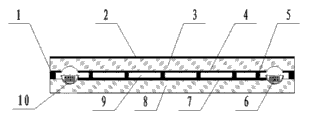
Fig. 1 is a section structure sketch map of the present invention.
Fig. 2 is a planar structure sketch map of the present invention.
Among the figure: 1 sealing-in scolder, 2 anti-reflection films, 3 upper glass plates, 4 anti-reflection films, 5 support columns, 6 getters, 7 photoelectricity conversion coatings, 8 lower glass plate, 9 vacuum chambers, 10 Thermo-insulation bowls, 11 electrodes.
Embodiment
In order more clearly to explain the present invention, the present invention is further described in conjunction with accompanying drawing.
Like Fig. 1 and shown in Figure 2, the vacuum glass that has the photoelectricity conversion coating provided by the present invention, it mainly comprises upper glass plates 3, lower glass plate 8, support column 5, sealing-in scolder 1, photoelectricity conversion coating 7, getter 6 etc.The surperficial light-plated electricity conversion coating 7 of a side lower glass plate 6 in the vacuum chamber of vacuum glass, the material of photoelectricity conversion coating can be chosen as required, on the two sides of photoelectricity conversion coating, is provided with lead connection vacuum seal solder flux place fixing electrode 11 is set.The material of the lower glass plate 6 of surface light-plated electricity conversion coating 7 is non-light transmissive materials such as pottery, metal.The photoelectricity conversion coating can also be made into photoelectricity separately and transform synusia, is placed in the interior side of vacuum chamber of vacuum glass.Two surfaces of upper glass plates have at least one side to be coated with one deck anti-reflection film 2 and 4; And go out pit as the getter groove in a side glass grinding of plated film; The inner getter 6 of placing; Around the upper surface of lower glass plate 8, be uniformly distributed with sealing solder 1 afterwards, guarantee that sealing solder 1 is completely fixed electrode 11, must not occur becoming flexible.For guaranteeing that getter is unlikely when high-frequency heating activates heat is passed to glass, around getter 6, Thermo-insulation bowl 10 can be set.
Support column adopts radius r=0.3-0.5mm, cylindrical type metal material or the ceramic material of height h=0.1-0.5mm.Support column is arranged in the vacuum chamber of vacuum glass, and an end contacts with the photoelectricity conversion coating, and the other end contacts with glass plate.The vacuum glass that has the photoelectricity conversion coating completes and afterwards leans on atmospheric effect can it be completely fixed and guarantee the thickness of vacuum layer.The thickness of the vacuum layer of vacuum glass (gap between upper glass plates and the lower glass plate) 0.1mm-0.5mm, promptly the height with support column adapts.Adopt chemical vapour deposition technique with photoelectricity conversion coating 7, deposit to lower glass plate 7 surfaces like amorphous silicon photoelectric conversion materials such as monocrystalline silicon, polysilicon, GaAs.Lower-glass 7 in the present embodiment can adopt materials such as pottery, metal.
Be provided with sealing solder around upper glass plates and the lower glass plate; Before being coated with scolder earlier with the 10mm scope sandblast grinding and guarantee certain roughness of lower glass plate inner surface apart from the border; Can effectively guarantee the intensity and the reliability of welding like this, the scolder both sides are glass, and lead passes through from scolder.The vacuum seal solder flux can be chosen as required; But must guarantee to adopt can be tight with two glass plates bonding, air tight, non-conductive, keep vacuum degree to reach the scolder of the service life of standard, for example low-temperature lead-free glass dust, insulating material are with glass dust, various powdered metallurgical material and nanotube-solder etc.The photoelectricity conversion coating is that identical materials or two kinds of different semi-conducting materials are made the PN junction battery structure, and material is amorphous silicon photoelectric conversion materials such as monocrystalline silicon, polysilicon and GaAs.
When the radiation of the vacuum glass that has the photoelectricity conversion coating through light, photoelectricity conversion coating 7 is an electric energy with transform light energy, and electric energy is deposited subsequent use or directly outwards power supply in the battery through the electrode 11 that is embedded in the sealing-in scolder 1, realizes the conversion and the utilization of photoelectricity.The conversion of solar energy of using the back to see through flat photo-thermal opto-electronic conversion hollow plate glass with the heat accumulation coordinative composition of equipments is heat energy.Such design can not only realize the rapid conversion of photo-thermal, more can effectively reduce the temperature of photoelectricity conversion coating, improves the efficient of opto-electronic conversion.
Claims (7)
1. vacuum glass that has the photoelectricity conversion coating; Comprise the vacuum glass that upper glass plates, support column, vacuum seal solder flux, lower glass plate, getter constitute; It is characterized in that described vacuum glass is provided with the photoelectricity conversion coating in a side of vacuum chamber, on the two sides of photoelectricity conversion coating, be provided with lead connection vacuum seal solder flux place fixing electrode is set.
2. the vacuum glass that has the photoelectricity conversion coating according to claim 1 is characterized in that having at least in the upper and lower surfaces of upper glass plates of described vacuum glass being coated with the anti-reflection film that increases the glass light transmittance on the glass plate.
3. the vacuum glass that has the photoelectricity conversion coating according to claim 1 is characterized in that the described glass plate that is provided with photoelectricity conversion coating one side is the ceramic wafer or the metallic plate of non-light transmissive material.
4. the vacuum glass that has the photoelectricity conversion coating according to claim 1 is characterized in that described support column one end contacts with the photoelectricity conversion coating, and the other end contacts with glass plate.
5. the vacuum glass that has the photoelectricity conversion coating according to claim 1 is characterized in that said photoelectricity conversion coating is plated in the upper side of the interior lower glass plate of vacuum layer of vacuum glass.
6. the vacuum glass that has the photoelectricity conversion coating according to claim 1 is characterized in that said photoelectricity conversion coating is that the photoelectricity of making separately transforms synusia, and photoelectricity transforms the interior side of vacuum chamber that synusia is placed in vacuum glass.
7. the vacuum glass that has the photoelectricity conversion coating according to claim 1; It is characterized in that said photoelectricity conversion coating is that identical materials or two kinds of different semi-conducting materials are made the PN junction battery structure, material is amorphous silicon photoelectric conversion materials such as monocrystalline silicon, polysilicon and GaAs.
Priority Applications (1)
| Application Number | Priority Date | Filing Date | Title |
|---|---|---|---|
| CN2011104524638A CN102544150A (en) | 2011-12-30 | 2011-12-30 | Vacuum glass with photoelectric conversion layer |
Applications Claiming Priority (1)
| Application Number | Priority Date | Filing Date | Title |
|---|---|---|---|
| CN2011104524638A CN102544150A (en) | 2011-12-30 | 2011-12-30 | Vacuum glass with photoelectric conversion layer |
Publications (1)
| Publication Number | Publication Date |
|---|---|
| CN102544150A true CN102544150A (en) | 2012-07-04 |
Family
ID=46350597
Family Applications (1)
| Application Number | Title | Priority Date | Filing Date |
|---|---|---|---|
| CN2011104524638A Pending CN102544150A (en) | 2011-12-30 | 2011-12-30 | Vacuum glass with photoelectric conversion layer |
Country Status (1)
| Country | Link |
|---|---|
| CN (1) | CN102544150A (en) |
Cited By (4)
| Publication number | Priority date | Publication date | Assignee | Title |
|---|---|---|---|---|
| CN102900316A (en) * | 2012-10-26 | 2013-01-30 | 扬州大学 | Vacuum glass provided with clathrate metal frame |
| CN104718341A (en) * | 2012-07-31 | 2015-06-17 | 葛迪恩实业公司 | Vacuum insulated glass (VIG) window unit with getter structure and method of making same |
| CN106698976A (en) * | 2015-11-18 | 2017-05-24 | 中国南玻集团股份有限公司 | Low-pressure vacuum energy-saving glass and preparation method thereof |
| CN107444086A (en) * | 2017-07-21 | 2017-12-08 | 常熟市江威真空玻璃有限公司 | Safe automobile-used vacuum photoelectric conversion skylight condensing glass |
Citations (3)
| Publication number | Priority date | Publication date | Assignee | Title |
|---|---|---|---|---|
| CN201024842Y (en) * | 2007-03-29 | 2008-02-20 | 深圳市瑞华建设股份有限公司 | Solar energy photovoltaic cell hollow glass assembly |
| CN101852054A (en) * | 2010-06-10 | 2010-10-06 | 扬州大学 | Vacuum plate glass |
| CN202395002U (en) * | 2011-12-30 | 2012-08-22 | 扬州大学 | Vacuum glass with photoelectric converting layer |
-
2011
- 2011-12-30 CN CN2011104524638A patent/CN102544150A/en active Pending
Patent Citations (3)
| Publication number | Priority date | Publication date | Assignee | Title |
|---|---|---|---|---|
| CN201024842Y (en) * | 2007-03-29 | 2008-02-20 | 深圳市瑞华建设股份有限公司 | Solar energy photovoltaic cell hollow glass assembly |
| CN101852054A (en) * | 2010-06-10 | 2010-10-06 | 扬州大学 | Vacuum plate glass |
| CN202395002U (en) * | 2011-12-30 | 2012-08-22 | 扬州大学 | Vacuum glass with photoelectric converting layer |
Cited By (5)
| Publication number | Priority date | Publication date | Assignee | Title |
|---|---|---|---|---|
| CN104718341A (en) * | 2012-07-31 | 2015-06-17 | 葛迪恩实业公司 | Vacuum insulated glass (VIG) window unit with getter structure and method of making same |
| EP2880236B1 (en) * | 2012-07-31 | 2024-05-29 | Guardian Glass, LLC | Vacuum insulated glass (vig) window unit with getter structure and method of making same |
| CN102900316A (en) * | 2012-10-26 | 2013-01-30 | 扬州大学 | Vacuum glass provided with clathrate metal frame |
| CN106698976A (en) * | 2015-11-18 | 2017-05-24 | 中国南玻集团股份有限公司 | Low-pressure vacuum energy-saving glass and preparation method thereof |
| CN107444086A (en) * | 2017-07-21 | 2017-12-08 | 常熟市江威真空玻璃有限公司 | Safe automobile-used vacuum photoelectric conversion skylight condensing glass |
Similar Documents
| Publication | Publication Date | Title |
|---|---|---|
| CN202395002U (en) | Vacuum glass with photoelectric converting layer | |
| CN102544150A (en) | Vacuum glass with photoelectric conversion layer | |
| CN103378204A (en) | Photovoltaic module and preparation method thereof | |
| CN102587792A (en) | Vacuum glass window with solar cell | |
| WO2011075967A1 (en) | Enamel solar building wall panel | |
| KR101232034B1 (en) | Solar cell module integrated with heat radiating package | |
| CN103022199A (en) | BIPV (building integrated photovoltaic) solar module and manufacturing method thereof | |
| WO2008120251A1 (en) | Ceramic tile with surface functionalized with photovoltaic cells | |
| WO2021238175A1 (en) | Double-sided light-transmitting cadmium telluride solar cell and preparation method therefor | |
| CN102315304A (en) | Solar assembly for integrating photovoltaic building as well as back plate and modifying method thereof | |
| US20220085757A1 (en) | Hybrid solar panel for producing electrical energy and thermal energy | |
| CN202307950U (en) | Solar battery assembly for photovoltaic building integration and back board thereof | |
| CN208738277U (en) | Solar battery glass structure | |
| CN203687419U (en) | Non-vacuum solar energy collector tube | |
| CN202926118U (en) | Energy-saving multi-layer vacuum sheet glass capable of changing colors under action of energization | |
| JP2004356397A (en) | Cylindrical photoelectric converter | |
| CN112909112B (en) | Photovoltaic module for improving photoelectric conversion efficiency and preparation method thereof | |
| CN102569473A (en) | Concentric-circle vacuum photo-thermal photoelectric conversion glass tube | |
| CN203288627U (en) | FRP-double-layer vacuum glass photovoltaic member | |
| CN102034615B (en) | Preparation method of dye-sensitized solar cell provided with light reflecting layer | |
| CN103673351B (en) | U-shaped vacuum hot tube type vacuum photo-thermal photoelectric conversion glass tube | |
| CN103972321B (en) | Fibrous silicon-based thin-film solar cell and preparation method thereof | |
| CN105470335A (en) | Photovoltaic vacuum glass and preparation method | |
| CN101902846A (en) | Nano-silicon conductive ceramic electrical heating tube element and manufacture method thereof | |
| CN202454567U (en) | Concentric vacuum light heat and light electricity conversion glass tube |
Legal Events
| Date | Code | Title | Description |
|---|---|---|---|
| C06 | Publication | ||
| PB01 | Publication | ||
| C10 | Entry into substantive examination | ||
| SE01 | Entry into force of request for substantive examination | ||
| C02 | Deemed withdrawal of patent application after publication (patent law 2001) | ||
| WD01 | Invention patent application deemed withdrawn after publication |
Application publication date: 20120704 |