CN102528362A - Positioning and propping device used for splicing and spot welding of U-shaped groove in main girder of bridge crane - Google Patents
Positioning and propping device used for splicing and spot welding of U-shaped groove in main girder of bridge crane Download PDFInfo
- Publication number
- CN102528362A CN102528362A CN2012100196183A CN201210019618A CN102528362A CN 102528362 A CN102528362 A CN 102528362A CN 2012100196183 A CN2012100196183 A CN 2012100196183A CN 201210019618 A CN201210019618 A CN 201210019618A CN 102528362 A CN102528362 A CN 102528362A
- Authority
- CN
- China
- Prior art keywords
- bridge crane
- splicing
- girder
- main girder
- shaped groove
- Prior art date
- Legal status (The legal status is an assumption and is not a legal conclusion. Google has not performed a legal analysis and makes no representation as to the accuracy of the status listed.)
- Pending
Links
Images


Landscapes
- Bridges Or Land Bridges (AREA)
- Leg Units, Guards, And Driving Tracks Of Cranes (AREA)
Abstract
The invention discloses a positioning and propping device used for splicing and spot welding of a U-shaped groove in a main girder of a bridge crane. The positioning and propping device comprises two fixed rails and a propping device capable of walking on the two fixed rails; the main girder of the bridge crane can pass through a passage formed by the two fixed rails and the propping device arranged on the two fixed rails; the propping device comprises a rectangular framework; and propping screw rods used for propping against the U-shaped groove in the main girder of the bridge crane are arranged on a longitudinal girder of the rectangular framework at intervals. Through the structure, when the positioning and propping device used for splicing and spot welding of the U-shaped groove in the main girder of the bridge crane is in use, the main girder of the bridge crane can be arranged on a frame placed between the two rails in advance, and then the splicing position and the size of the U-shaped groove in the main girder can be adjusted and corrected by adjusting the propping screw rods on the longitudinal girder of the rectangular framework placed on the propping device, so that the splicing straightness and the splicing quality can be effectively ensured when the U-shaped groove in the main girder of the bridge crane is spliced.
Description
Technical field
The present invention relates to a kind of location holding device that is used for the girder U-lag splicing spot welding of bridge crane.
Background technology
The girder U-lag of electric single-beam bridge crane splicing in the past all is manual splicing; Because the longer dimension of girder; Splice point is more, and particularly young workman is more and more, often occurs the splicing phenomenon that linearity is relatively poor, joining quality is bad in the production process; Therefore, be starved of the joining quality that a kind of device is protected positive girder U-lag.
Summary of the invention
The technical problem that the present invention will solve can guarantee to splice linearity when providing a kind of girder U-lag splicing at electric single-beam bridge crane and splice the location holding device of spot welding with joining quality and with splicing workman's technology with the girder U-lag that is used for bridge crane that experience has nothing to do.
For solving the problems of the technologies described above, the present invention is used for the location holding device of the girder U-lag splicing spot welding of bridge crane, comprises two trapped orbits and the holding device that can on these two trapped orbits, walk; Said holding device comprises two rectangular frames; Each rectangular frame has longitudinal and cross beam; The bottom of each rectangular frame is provided with the walking mechanism that can walk in orbit that matches with trapped orbit, is connected with the connection side bar between the crossbeam of two rectangular frame upper ends; The girder of said bridge crane can pass through with being arranged in the passage that said holding device surrounded on said two trapped orbits from said two trapped orbits; The space is provided with the fastening screw of the girder U-lag that is used for the said bridge crane of roof pressure on the longeron of said each rectangular frame.
Adopt the location holding device of the girder U-lag splicing spot welding that is used for bridge crane of said structure; Can place the girder of bridge crane during use and be arranged in advance on two frames between the track; The fastening screw that is arranged on the rectangular frame longeron on the holding device through adjustment is afterwards adjusted the stitching position and the size of the said girder U-lag of calibration, and then can guarantee the splicing linearity and the joining quality in girder U-lag when splicing of bridge crane effectively.
Description of drawings
Below in conjunction with accompanying drawing the present invention is done to specify further.
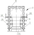
Main TV structure sketch map when Fig. 1 is the user mode of location holding device of the present invention's girder U-lag splicing spot welding of being used for bridge crane.
Plan structure sketch map when Fig. 2 is the user mode of location holding device of the girder U-lag splicing spot welding that is used for bridge crane shown in Figure 1.
Fig. 3 is the side-looking structure for amplifying sketch map that the girder U-lag that is used for bridge crane shown in Figure 1 splices the location holding device of spot welding.
The specific embodiment
Referring to Fig. 1-Fig. 3, the present invention is used for the location holding device of the girder U-lag splicing spot welding of bridge crane, and it comprises two trapped orbits 1,2 and the holding device 3 that can on these two trapped orbits 1,2, walk; Said holding device 3 comprises two rectangular frames 4; Each rectangular frame has longeron 5 and crossbeam 6; The bottom of each rectangular frame 4 is provided with to be connected with between the crossbeam 6 of 7, two rectangular frame 4 upper ends of the walking mechanism that can walk in orbit of matching with trapped orbit and connects side bar 8; The girder 9 of said bridge crane can and be arranged in the passage that the said holding device 3 on said two trapped orbits surrounded from said two trapped orbits 1,2 and pass through; 5 spaces are provided with the fastening screw 10 of the girder 9U shape groove that is used for the said bridge crane of roof pressure on the longeron of said each rectangular frame 4.Can place the girder 9 of bridge crane during use to be arranged in advance on two tracks 1, the frame 11 between 2, be arranged on stitching position and the size that fastening screw 10 on the rectangular frame longeron 5 on the holding device 3 is adjusted the said girder U-lag of calibration through adjustment afterwards.
Claims (1)
1. a girder U-lag that is used for bridge crane splices the location holding device of spot welding, and it is characterized in that: it comprises two trapped orbits and the holding device that can on these two trapped orbits, walk; Said holding device comprises two rectangular frames; Each rectangular frame has longitudinal and cross beam; The bottom of each rectangular frame is provided with the walking mechanism that can walk in orbit that matches with trapped orbit, is connected with the connection side bar between the crossbeam of two rectangular frame upper ends; The girder of said bridge crane can pass through with being arranged in the passage that said holding device surrounded on said two trapped orbits from said two trapped orbits; The space is provided with the fastening screw of the girder U-lag that is used for the said bridge crane of roof pressure on the longeron of said each rectangular frame.
Priority Applications (1)
| Application Number | Priority Date | Filing Date | Title |
|---|---|---|---|
| CN2012100196183A CN102528362A (en) | 2012-01-25 | 2012-01-25 | Positioning and propping device used for splicing and spot welding of U-shaped groove in main girder of bridge crane |
Applications Claiming Priority (1)
| Application Number | Priority Date | Filing Date | Title |
|---|---|---|---|
| CN2012100196183A CN102528362A (en) | 2012-01-25 | 2012-01-25 | Positioning and propping device used for splicing and spot welding of U-shaped groove in main girder of bridge crane |
Publications (1)
| Publication Number | Publication Date |
|---|---|
| CN102528362A true CN102528362A (en) | 2012-07-04 |
Family
ID=46337061
Family Applications (1)
| Application Number | Title | Priority Date | Filing Date |
|---|---|---|---|
| CN2012100196183A Pending CN102528362A (en) | 2012-01-25 | 2012-01-25 | Positioning and propping device used for splicing and spot welding of U-shaped groove in main girder of bridge crane |
Country Status (1)
| Country | Link |
|---|---|
| CN (1) | CN102528362A (en) |
Cited By (1)
| Publication number | Priority date | Publication date | Assignee | Title |
|---|---|---|---|---|
| CN117900672A (en) * | 2024-02-23 | 2024-04-19 | 河北正钢钢结构有限公司 | Container house quick welding platform |
Citations (4)
| Publication number | Priority date | Publication date | Assignee | Title |
|---|---|---|---|---|
| SU1380890A1 (en) * | 1986-04-03 | 1988-03-15 | Запорожский Проектно-Конструкторский И Технологический Институт | Jig for assembling and welding articles |
| CN201079895Y (en) * | 2007-08-24 | 2008-07-02 | 中国南车集团戚墅堰机车车辆厂 | Roll-over stand for locomotive frame side beam group welding |
| CN201849911U (en) * | 2010-10-18 | 2011-06-01 | 中冶成工上海五冶建设有限公司 | Conveying device for heavy equipment |
| CN202398974U (en) * | 2012-01-25 | 2012-08-29 | 辽宁三洋重工起重机装备有限公司 | Positioning and propping device for splicing spot welding of U-shaped groove of main beam of overhead crane |
-
2012
- 2012-01-25 CN CN2012100196183A patent/CN102528362A/en active Pending
Patent Citations (4)
| Publication number | Priority date | Publication date | Assignee | Title |
|---|---|---|---|---|
| SU1380890A1 (en) * | 1986-04-03 | 1988-03-15 | Запорожский Проектно-Конструкторский И Технологический Институт | Jig for assembling and welding articles |
| CN201079895Y (en) * | 2007-08-24 | 2008-07-02 | 中国南车集团戚墅堰机车车辆厂 | Roll-over stand for locomotive frame side beam group welding |
| CN201849911U (en) * | 2010-10-18 | 2011-06-01 | 中冶成工上海五冶建设有限公司 | Conveying device for heavy equipment |
| CN202398974U (en) * | 2012-01-25 | 2012-08-29 | 辽宁三洋重工起重机装备有限公司 | Positioning and propping device for splicing spot welding of U-shaped groove of main beam of overhead crane |
Cited By (1)
| Publication number | Priority date | Publication date | Assignee | Title |
|---|---|---|---|---|
| CN117900672A (en) * | 2024-02-23 | 2024-04-19 | 河北正钢钢结构有限公司 | Container house quick welding platform |
Similar Documents
| Publication | Publication Date | Title |
|---|---|---|
| CN104060523A (en) | Ultra-large type bridge box girder component, dedicated jig frame and assembling method thereof | |
| US10138605B2 (en) | Railway track sleeper squaring device and self-propelled machine which comprises this device | |
| MX2013000330A (en) | Bridge shoring system. | |
| CN105499878A (en) | Directional deformation prevention low-residual stress welding fixture | |
| CN103147409B (en) | Closing construction method for steel bar-concrete superposed beam cable-stayed bridge | |
| CN103321247B (en) | Adjustable, detachable and reusable nose support guiding device and method of immersed tube tunnel | |
| CN104014970B (en) | Adjustable steel structure field welding support frame | |
| CN202398974U (en) | Positioning and propping device for splicing spot welding of U-shaped groove of main beam of overhead crane | |
| JP2015078561A (en) | Erection method of steel structure | |
| CN102528362A (en) | Positioning and propping device used for splicing and spot welding of U-shaped groove in main girder of bridge crane | |
| CN104625340A (en) | Manual welding method of high-strength small-size H-shaped steel | |
| CN104594183A (en) | Assembling type reinforced concrete T-shaped beam | |
| CN103840347A (en) | Rail guiding type supporting frame for wire compression joint machine | |
| CN205907597U (en) | Truss -like breast moving platform device | |
| CN204644854U (en) | Simple detachable belt gap bridge | |
| JP2004300888A (en) | Irregularity correcting tool for steel-frame column | |
| CN104759775A (en) | Tyre crane portal frame welding method | |
| CN203296065U (en) | Adjustable, detachable and reusable nose supporting guide device of immersed tunnel | |
| JP2016205043A (en) | Anchor bolt holding jig and anchor bolt support device using the same | |
| CN104759773A (en) | Tyre crane portal frame welding method | |
| CN203900795U (en) | Adjustable steel structure field welding supporting frame | |
| CN103061411A (en) | Support controllable in buckling deformation direction and frame adopting same | |
| CN103806352B (en) | Framed bent assembling control method and device | |
| CN203610890U (en) | Fixing device for rectangular box type structure in welding | |
| CN206172538U (en) | A interim strutting arrangement that is arranged in steel case roof beam transportation |
Legal Events
| Date | Code | Title | Description |
|---|---|---|---|
| C06 | Publication | ||
| PB01 | Publication | ||
| C10 | Entry into substantive examination | ||
| SE01 | Entry into force of request for substantive examination | ||
| C02 | Deemed withdrawal of patent application after publication (patent law 2001) | ||
| WD01 | Invention patent application deemed withdrawn after publication |
Application publication date: 20120704 |