CN102491153B - Design of traction system of 6:1 motor-room-free cargo elevator - Google Patents
Design of traction system of 6:1 motor-room-free cargo elevator Download PDFInfo
- Publication number
- CN102491153B CN102491153B CN201110453467.8A CN201110453467A CN102491153B CN 102491153 B CN102491153 B CN 102491153B CN 201110453467 A CN201110453467 A CN 201110453467A CN 102491153 B CN102491153 B CN 102491153B
- Authority
- CN
- China
- Prior art keywords
- wheel
- side guide
- traction
- guide wheel
- sedan
- Prior art date
- Legal status (The legal status is an assumption and is not a legal conclusion. Google has not performed a legal analysis and makes no representation as to the accuracy of the status listed.)
- Active
Links
- 238000000034 method Methods 0.000 claims abstract description 14
- 230000009286 beneficial effect Effects 0.000 abstract description 4
- 238000005265 energy consumption Methods 0.000 abstract description 4
- 229910000831 Steel Inorganic materials 0.000 description 2
- 230000007812 deficiency Effects 0.000 description 2
- 238000010586 diagram Methods 0.000 description 2
- 239000010959 steel Substances 0.000 description 2
- 239000000725 suspension Substances 0.000 description 2
- 230000001360 synchronised effect Effects 0.000 description 2
- 238000005516 engineering process Methods 0.000 description 1
Images


Landscapes
- Lift-Guide Devices, And Elevator Ropes And Cables (AREA)
Abstract
本发明公开了一种6:1无机房载货电梯的曳引系统设计方法,包含侧导轮(1)、对重轮(2)、曳引轮(3)、曳引绳(4)、对重体(5)、轿底轮(6)、轿厢(7),曳引绳(4)一端依次经由曳引轮(3)、轿底轮(6)、轿底轮(6)、侧导轮(1)、轿底轮(6)、轿底轮(6)、侧导轮(1)、轿底轮(6)、轿底轮(6)至固定绳头(M),曳引绳(4)的另一端依次经由曳引轮(3)、对重轮(2)、侧导轮(1)、对重轮(2)、侧导轮(1)、对重轮(2)至固定绳头(N)。本发明的有益效果在于:能使电梯更平稳,运行更安全,能有效降低能耗,广泛应用于6:1无机房载货电梯中。
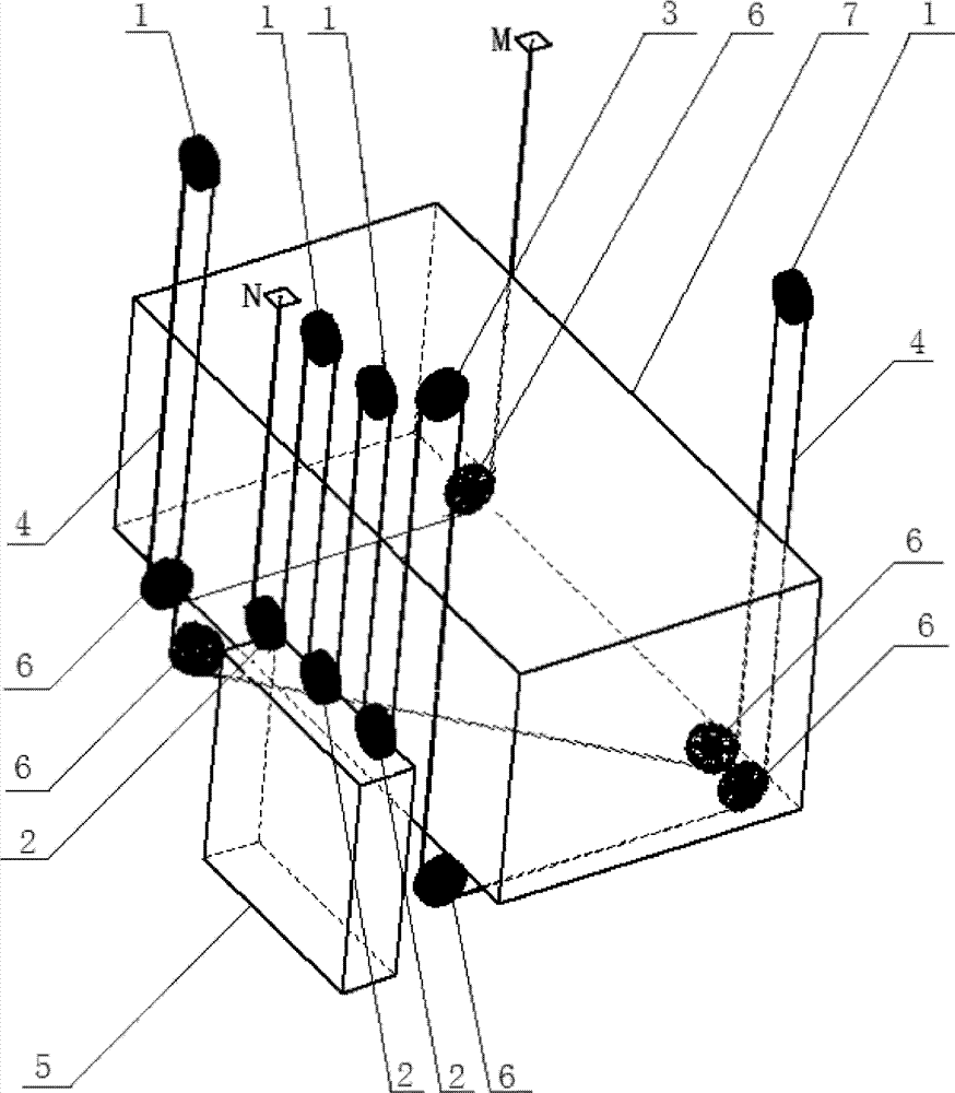
The invention discloses a design method for a traction system of a 6:1 machine room-less freight elevator, which comprises a side guide wheel (1), a counterweight wheel (2), a traction wheel (3), a traction rope (4), Counterweight (5), car bottom wheel (6), car (7), one end of traction rope (4) passes through traction sheave (3), car bottom wheel (6), car bottom wheel (6), side Guide wheel (1), car bottom wheel (6), car bottom wheel (6), side guide wheel (1), car bottom wheel (6), car bottom wheel (6) to the fixed rope head (M), traction The other end of the rope (4) passes through the traction sheave (3), the counterwheel (2), the side guide wheel (1), the counterwheel (2), the side guide wheel (1), and the counterwheel (2) to the fixed end of the rope (N). The beneficial effects of the present invention are: the elevator can be made more stable, the operation is safer, the energy consumption can be effectively reduced, and the elevator is widely used in 6:1 machine-room-less freight elevators.
Description
技术领域 technical field
本发明属于电梯领域,尤其涉及电梯的曳引系统设计方法,具体地说,涉及6:1无机房载货电梯的曳引系统设计方法。 The invention belongs to the field of elevators, in particular to a method for designing a traction system of an elevator, in particular to a method for designing a traction system of a 6:1 machine room-less freight elevator.
背景技术 Background technique
电梯曳引系统是电梯系统的重要设计环节之一,它关系到电梯的正常、平稳、连续运行,是电梯运行安全的重要保障。 The elevator traction system is one of the important design links of the elevator system. It is related to the normal, stable and continuous operation of the elevator and is an important guarantee for the safety of the elevator operation.
对于无机房载货电梯,为采用永磁同步曳引机,目前市面上都是采用4:1的曳引方式。如图1所示(该图仅示出了曳引系统的部分构件),它包含侧导轮1、对重轮2、曳引轮3、曳引绳4、对重体5、轿底轮6和轿厢7,轿底轮6的个数为4个,设置在轿厢7的下方;曳引绳4一端经由曳引轮3——轿底轮6——侧导轮1——轿底轮6,并由后一个轿底轮6出并连至固定绳头M,另一端经由曳引轮3——对重轮2——侧导轮1——对重轮2出并连至另一固定绳头N。
For machine-room-less freight elevators, in order to use permanent magnet synchronous traction machines, the 4:1 traction mode is currently used on the market. As shown in Figure 1 (this figure only shows some components of the traction system), it includes a
上述设计的不足在于:当电梯载重量超过5000kg时,由于主轴载荷和驱动转矩太大而无法使用永磁同步无齿轮曳引机,即使采用4:1的曳引系统设计方法也不能满足要求。 The disadvantage of the above design is that when the load of the elevator exceeds 5000kg, the permanent magnet synchronous gearless traction machine cannot be used because the main shaft load and driving torque are too large, and even the 4:1 traction system design method cannot meet the requirements .
发明内容 Contents of the invention
针对当前技术的不足之处,本发明特提出一种新的曳引系统设计方法,它不仅能解决现有技术中的不足,还具有其它有益效果。 Aiming at the deficiencies of the current technology, the present invention proposes a new design method of the traction system, which not only can solve the deficiencies of the prior art, but also has other beneficial effects.
6:1无机房载货电梯的曳引系统设计方法,包含侧导轮1、对重轮2、曳引轮3、曳引绳4、对重体5、轿底轮6、轿厢7,其中,侧导轮1的数目为4个或以上,对重轮2的数目为3个;轿底轮6的数目为6个,位于轿厢7的底部;侧导轮1中的2个位于对重轮2上方,另2个或以上位于所述的轿底轮6上方;曳引绳4一端依次经由曳引轮3、轿底轮6、轿底轮6、侧导轮1、轿底轮6、轿底轮6、侧导轮1、轿底轮6、轿底轮6至固定绳头M,曳引绳4的另一端依次经由曳引轮3、对重轮2、侧导轮1、对重轮2、侧导轮1、对重轮2至固定绳头N。
6:1 traction system design method of machine room-less freight elevator, including
上述设置中,对重轮2水平并排设置在所述的对重体5的上方;侧导轮1中的2个在垂直方向上分别处于所述的对重轮2水平间隔形成的空隙上,另外2个或以上分别位于轿底轮6的上方。这样设置,可以使电梯的运行更安全、平稳,能有效降低能耗。
In the above setting, the
为了实现本发明目的,达成6:1无机房载货电梯的曳引系统设计方法,本发明的轿底轮6的数目为6个,且两两一组,共分3 组;为解决轿厢悬挂的受力平衡问题,3组轿底轮的中间1组采用斜摆或平行等方式。
In order to realize the object of the present invention, reach the traction system design method of 6:1 machine-room-less freight elevator, the number of
本发明中的绳轮,即侧导轮1、对重轮2、曳引轮3等,分别布置在轿厢7两侧的上方和对重的上方。井道顶部的两侧布置钢梁用以安装绳轮、绳头M/N和曳引机。该部分内容属于电梯的曳引系统通用设置,故不再赘述。
Sheaves among the present invention, namely
本发明的有益效果在于:由于轿厢上设置3个轿底轮6、对重体5上设置3个对重轮2,且侧导轮为4个或以上,其中的2个或以上对应于轿底轮6,另2个对应于对重轮2,对称布置使得对重更平稳,运行更安全。同时,由于采用6:1曳引使曳引轮的主轴载荷比4:1曳引减少33%,而且使曳引机的驱动转矩减少33%,能耗得到有效降低。
The beneficial effect of the present invention is: because 3
由于上述有益效果,本发明广泛应用于无机房6:1曳引载货电梯中。 Due to the above beneficial effects, the present invention is widely used in machine room-less 6:1 traction freight elevators. the
附图说明 Description of drawings
图1是现有技术4:1无机房曳引系统结构示意图; Fig. 1 is a schematic structural diagram of a 4:1 machine room-less traction system in the prior art;
图2是本发明的系统结构示意图。 Fig. 2 is a schematic diagram of the system structure of the present invention. the
标识说明: 1—侧导轮;2—轿底轮;3--曳引轮;4—曳引绳;5—对重体;6—轿底轮;7—轿厢。 Identification instructions: 1—side guide wheel; 2—car bottom wheel; 3—traction sheave; 4—traction rope; 5—counterweight; 6—car bottom wheel; 7—car.
具体实施方式 Detailed ways
下面结合附图并以实施例的方式对本发明作进一步详细描述。 The present invention will be further described in detail below in conjunction with the accompanying drawings and in the form of embodiments.
如图2所示,6:1无机房载货电梯的曳引系统设计方法,包含侧导轮1、对重轮2、曳引轮3、曳引绳4、对重体5、轿底轮6、轿厢7,其中,侧导轮1的数目为4个或以上,对重轮2的数目为3个;轿底轮6的数目为6个,位于轿厢7的底部;侧导轮1中的2个位于对重轮2上方,另2个或以上位于所述的轿底轮6上方;曳引绳4一端依次经由曳引轮3 、轿底轮6、轿底轮6、侧导轮1、轿底轮6、轿底轮6、侧导轮1、轿底轮6、轿底轮6至固定绳头M,曳引绳4的另一端依次经由曳引轮3、对重轮2、侧导轮1、对重轮2、侧导轮1、对重轮2至固定绳头N。
As shown in Figure 2, the design method of the traction system of a 6:1 machine room-less freight elevator includes
图2中,对重轮2水平并排设置在所述的对重体5的上方;侧导轮1中的2个在垂直方向上分别处于所述的对重轮2水平间隔形成的空隙上,另外2个或以上分别位于轿底轮6的上方。轿底轮6两两一组,共分3 组,为解决轿厢悬挂的受力平衡问题,3组轿底轮的中间1组采用斜摆的方式。对重体5布置在轿厢7的一侧,对重上部布置3个或以上的绳轮。在井道的顶部布置5个或以上的绳轮,其中1个为曳引轮3,分别布置在轿厢7的两侧的上方和对重体5的上方。井道顶部的两侧布置钢梁用以安装绳轮、绳头M/N和曳引机。通过本发明的曳引系统设计方法,能使电梯平稳,运行更安全,能有效降低能耗。
In Fig. 2, the
Claims (2)
- The traction system design method of 1.6:1 machine room cargo lift, comprise side guide wheel (1), to roller (2), traction sheave (3), hoist ropes (4), pair weight (5), sedan-chair return pulley (6), car (7), it is characterized in that: the number of described side guide wheel (1) be 4 or more than, the described number to roller (2) is 3; The number of described sedan-chair return pulley (6) is 6, is positioned at the bottom of described car (7); In described side guide wheel (1) 2 are positioned at described to roller (2) top, and another 2 or above side guide wheel are positioned at described sedan-chair return pulley (6) top; Described hoist ropes (4) one end successively via traction sheave (3), sedan-chair return pulley (6), sedan-chair return pulley (6), side guide wheel (1), sedan-chair return pulley (6), sedan-chair return pulley (6), side guide wheel (1), sedan-chair return pulley (6), sedan-chair return pulley (6) to fixing fag end (M), the other end of described hoist ropes (4) successively via traction sheave (3), to roller (2), side guide wheel (1), to roller (2), side guide wheel (1), to roller (2) to fixing fag end (N); The described top that roller (2) horizontal Tile is arranged on to described pair weight (5); 2 in described side guide wheel (1) in vertical direction respectively on the described space that roller (2) horizontal interval (HI) is formed; Other 2 or lay respectively at above the top of described sedan-chair return pulley (6).
- 2. the traction system design method of 6:1 machine room cargo lift according to claim 1, is characterized in that: the number of described sedan-chair return pulley (6) is 6, and one group between two, totally 3 groups, the bottom of the car (7) described in being all positioned at.
Priority Applications (1)
| Application Number | Priority Date | Filing Date | Title |
|---|---|---|---|
| CN201110453467.8A CN102491153B (en) | 2011-12-29 | 2011-12-29 | Design of traction system of 6:1 motor-room-free cargo elevator |
Applications Claiming Priority (1)
| Application Number | Priority Date | Filing Date | Title |
|---|---|---|---|
| CN201110453467.8A CN102491153B (en) | 2011-12-29 | 2011-12-29 | Design of traction system of 6:1 motor-room-free cargo elevator |
Publications (2)
| Publication Number | Publication Date |
|---|---|
| CN102491153A CN102491153A (en) | 2012-06-13 |
| CN102491153B true CN102491153B (en) | 2014-04-30 |
Family
ID=46183024
Family Applications (1)
| Application Number | Title | Priority Date | Filing Date |
|---|---|---|---|
| CN201110453467.8A Active CN102491153B (en) | 2011-12-29 | 2011-12-29 | Design of traction system of 6:1 motor-room-free cargo elevator |
Country Status (1)
| Country | Link |
|---|---|
| CN (1) | CN102491153B (en) |
Families Citing this family (4)
| Publication number | Priority date | Publication date | Assignee | Title |
|---|---|---|---|---|
| CN107618963B (en) * | 2017-10-31 | 2023-02-28 | 杭州奥立达电梯有限公司 | Large-load goods elevator suspension system with traction ratio of 6 to 1 |
| CN110510485B (en) * | 2019-08-05 | 2024-03-01 | 菱王电梯有限公司 | Bow-shaped rope winding traction structure of shoe type 8 to 1 elevator without machine room |
| CN110668290B (en) * | 2019-09-18 | 2023-11-14 | 菱王电梯有限公司 | Bow-shaped elevator load-bearing structure |
| CN112173928A (en) * | 2020-10-26 | 2021-01-05 | 中科西奥电梯有限公司 | One is based on 6: 1-suspension type freight elevator traction structure |
Family Cites Families (9)
| Publication number | Priority date | Publication date | Assignee | Title |
|---|---|---|---|---|
| JP4270831B2 (en) * | 2002-09-24 | 2009-06-03 | 東芝エレベータ株式会社 | Machine roomless elevator |
| JPWO2005121008A1 (en) * | 2004-06-08 | 2008-04-10 | 三菱電機株式会社 | Elevator equipment |
| ATE411966T1 (en) * | 2004-07-12 | 2008-11-15 | Inventio Ag | ELEVATOR AND ROLLER ASSEMBLY FOR USE IN AN ELEVATOR |
| ITMI20062544A1 (en) * | 2006-12-29 | 2008-06-30 | L A Consulting S A S | ELEVATOR WITH BALANCING WEIGHT |
| CN201296591Y (en) * | 2008-11-26 | 2009-08-26 | 广东菱王电梯有限公司 | A 4:1 arrangement no machinery room cargo carrying elevator |
| CN101850925A (en) * | 2010-06-21 | 2010-10-06 | 马海英 | Arrangement method of elevator traction machine |
| CN201980832U (en) * | 2011-04-14 | 2011-09-21 | 广东菱王电梯有限公司 | Traction device for 4:1 small machine room freight elevator |
| CN102180393A (en) * | 2011-04-25 | 2011-09-14 | 杭州优迈科技有限公司 | Winding mode of elevator steel wire rope and elevator |
| CN202400713U (en) * | 2011-12-29 | 2012-08-29 | 广东菱王电梯有限公司 | Traction structure for 6:1 machine-room-free goods lift |
-
2011
- 2011-12-29 CN CN201110453467.8A patent/CN102491153B/en active Active
Also Published As
| Publication number | Publication date |
|---|---|
| CN102491153A (en) | 2012-06-13 |
Similar Documents
| Publication | Publication Date | Title |
|---|---|---|
| CN207418087U (en) | A kind of cargo lift tracting structure | |
| CN109626176B (en) | Traction structure of 12:1 cargo elevator | |
| CN102745578B (en) | Lift device | |
| CN209455877U (en) | A kind of elevator safety deceleration device | |
| CN202829217U (en) | Rear counterweight of a goods lift free of machine room | |
| CN102491153A (en) | Design of traction system of 6:1 motor-room-free cargo elevator | |
| CN105110140A (en) | Load change adaptive steel wire rope traction lifting system | |
| CN215666505U (en) | Dual-drive elevator | |
| CN203173653U (en) | Lower arranged type structure device of 4:1 machine-room-less freight elevator traction machine | |
| CN202272602U (en) | Layout structure of machine-room-less elevator | |
| CN202400713U (en) | Traction structure for 6:1 machine-room-free goods lift | |
| CN201211991Y (en) | Energy-saving double-car elevator | |
| CN204280998U (en) | Double end traction elevator | |
| CN208308191U (en) | A kind of double counterweight elevators | |
| CN201494986U (en) | Intelligent balanced energy-saving elevator system | |
| CN202038789U (en) | Traction device for freight elevator in 4:1 small machine room | |
| CN204689291U (en) | A kind of elevator front end state acquisition device | |
| CN211769678U (en) | Arched rope winding traction structure of bottom-supported 8:1 machine-room-less elevator | |
| CN104355206A (en) | 10-tonnage elevator | |
| CN209815442U (en) | Traction structure of 12: 1 cargo elevator | |
| CN212245836U (en) | A 12 to 1 traction structure for heavy-duty freight elevators | |
| CN204529036U (en) | A kind of elevator traction system | |
| CN210340019U (en) | An elevator traction mechanism | |
| CN207434801U (en) | A kind of anodontia towed elevator of large-tonnage | |
| CN202717479U (en) | Ultra high-speed elevator weight compensation device |
Legal Events
| Date | Code | Title | Description |
|---|---|---|---|
| C06 | Publication | ||
| PB01 | Publication | ||
| C10 | Entry into substantive examination | ||
| SE01 | Entry into force of request for substantive examination | ||
| C14 | Grant of patent or utility model | ||
| GR01 | Patent grant | ||
| C56 | Change in the name or address of the patentee | ||
| CP03 | Change of name, title or address |
Address after: 528225 Guangdong Province Nanhai District of Foshan City Shishan Shishan science and Technology Industrial Park North Park Patentee after: WINONE Elevator Co., Ltd. Address before: Nanhai District Guangdong city Foshan province 528200 summer Beiju Longnan Industrial Zone No. 15 (sea Guicheng eight) Patentee before: Guangdong WINONE Elevator Co., Ltd. |
|
| CP03 | Change of name, title or address |
Address after: 528200 North Park of Shishan Science and Technology Industrial Park, Shishan town, Nanhai District, Foshan City, Guangdong Province Patentee after: Lingwang Elevator Co.,Ltd. Address before: 528225 North Park of Shishan Science and Technology Industrial Park, Shishan town, Nanhai District, Foshan City, Guangdong Province Patentee before: WINONE ELEVATOR Co.,Ltd. |
|
| CP03 | Change of name, title or address |