Summary of the invention
The object of the present invention is to provide a kind of simple in structure, the solar recharging system of electricity consumption handling safety, when solar energy when residue input, charging stores dump energy to battery box; When use output was not gone up in the solar energy supply, surplus electricity of battery box and solar energy were supplied with inverter simultaneously; When solar energy did not have, storage battery was directly supplied with.
To defective of the prior art, the present invention provides a kind of solar recharging system, comprising: solar panel and battery box, and wherein, a control cabinet comprises:
One charger; Its input connects said solar panel; Output connects said battery box charging inlet; Said charger comprises charging circuit and charge protector, and said charge protector is used for after the voltage that loads on the said charging circuit reaches a standard value, breaking off this charging circuit;
One inverter, its input connects the output of said battery box, and said inverter comprises that a transformer, a rectification circuit connect and an inverter circuit;
First Pwm controller is used to control the input voltage of the primary coil of said transformer;
Thermal-shutdown circuit, it is connected with said first Pwm controller, is used for after said control the temperature inside the box reaches a preset value, sends signal to said first Pwm controller, turn-offs the input voltage of said transformer.
Above-mentioned solar recharging system, wherein, one second Pwm controller connects said inverter circuit, and said second Pwm controller is used for the voltage stabilizing of the output AC voltage of control inverter.
Above-mentioned solar recharging system wherein, also comprises in the said control cabinet:
Under-voltage protecting circuit, it is connected with said first Pwm controller, is used for after said input voltage drops to a preset value, sends signal to said first Pwm controller, turn-offs the input voltage of said transformer.
Above-mentioned solar recharging system, wherein, said control cabinet also comprises:
Overvoltage crowbar, it is connected with said first Pwm controller, is used for after said input voltage reaches a preset value, sends signal to said first Pwm controller, turn-offs the input voltage of said transformer.
Above-mentioned solar recharging system, wherein, said control cabinet also comprises:
Overload protecting circuit, it is connected with said first Pwm controller, is used for when load is excessive, sends signal to said first Pwm controller, turn-offs the input voltage of said transformer.
Above-mentioned solar recharging system, wherein, said control cabinet also comprises:
Short-circuit protection circuit, it is connected with said second Pwm controller, is used for when load is excessive, sends signal to said second Pwm controller, turn-offs said inversion output.
Above-mentioned solar recharging system, wherein, said solar energy electroplax is single-crystalline-silicon solar-cell panel or polysilicon solar cell plate.
The present invention is through being installed in charger and inverter in the control cabinet, and protective circuit is set improves the product safety performance, when using product of the present invention, uses hommization, and the solar energy delivery efficiency is higher.
Embodiment
Come solar recharging equipment of the present invention is done explanation in further detail below in conjunction with Figure of description and embodiment.
Fig. 1 illustrates according to the first embodiment of the present invention, a kind of operation principle block diagram of solar recharging system.Particularly, in the present embodiment, said solar recharging system comprises solar panel 1, control cabinet 2, and battery box 3 comprises charger 201 in the control cabinet 2, inverter 202, inverter protection control device 203.System of the present invention with charger and inverter as being wholely set in control cabinet, thereby make system easy to be attractive in appearance.
Wherein, the input of charger 201 is connected with described solar panel 1, the output of charger 201 is connected with the input of battery box 3, and battery box 3 outputs are connected with the direct current input of inverter 4.
The operation principle of the solar recharging equipment of present embodiment is following: at first, solar panel 1 receives and produces dc voltage and current through opto-electronic conversion after ambient light is shone, and dc voltage and current is converted into alternating current output through inverter 202; When solar energy input residue, dump energy stores for battery box 2 chargings, and particularly, said dc voltage and current is given described battery box 3 chargings through being converted into charging current voltage behind the charger 201; When output go up was not used in the solar energy supply, electricity and solar energy were supplied with inverter 202 simultaneously surplus the battery box 3; When lacking solar energy, storage battery is directly supplied with, and battery box 3 offers inverter 202 with electric energy stored and carries out the conversion that direct current is delivered stream.Solar energy changes into civilian alternating current and exports to user's use the most at last, promptly can be electric as long as the user connects loads to the output of the inverter 202 of this solar recharging equipment.Under-voltage when in addition, the inverter of this solar recharging equipment protection control device 203 can also charge to charging system, implementation Automatic Control such as mistake is put, excess temperature.The solar recharging equipment of present embodiment, simple in structure, fitting operation is simple, and convenient moving is applicable in a lot of environment and works.
In a preference, solar panel 1 is a single-crystalline-silicon solar-cell panel.It will be appreciated by those skilled in the art that said solar recharging system also can adopt a plurality of solar panels, said variation does not influence the enforcement of present embodiment, does not repeat them here.
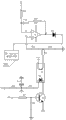
Fig. 2 illustrates according to a second embodiment of the present invention, a kind of charger circuit sketch map of solar recharging system.With reference to embodiment shown in Figure 1, in the present embodiment, said charger input connects said solar panel, and its output connects said battery box charging inlet; Wherein, said charger is made up of charge protector 2001 and charging circuit 2002, and charge protector 2001 is used for after the voltage that loads on the said charging circuit reaches a standard value, breaking off this charging circuit.Particularly, in the present embodiment, the solar panel output voltage is 15V; The battery box output voltage is 12V, and with reference to figure 2, solar energy input SOLAR+15V adds fashionable; Resistance R 5 detects to judge whether solar energy adds in the charger, makes triode N2 conducting over the ground drop-down with the R6 dividing potential drop, and this moment, resistance R 3 was obtained battery voltage effectively over the ground with R4; BATTERY+12V is as the reverse comparative voltage of voltage comparator ic 1A the 6th pin comparator; When voltage comparator ic 1A the 6th pin was lower than the reference voltage 2.5V of the 5th pin connection, the 7th pin output high potential promoted triode N1, relay J adhesive; Relay J normally-closed contact Jb connects a red light, and solar-electricity is bright to storage battery (not shown among Fig. 2) charging and red light R through relay adhesive adding diode D1 and D2 forward simultaneously; When battery box is full of electric energy; Battery voltage is carried in voltage comparator ic 1A the 6th pin will be higher than the 5th pin reference voltage 2.5V, and the 7th pin output electronegative potential promotes triode N1, not adhesive of relay J; Said relay J normally opened contact Jk connects a green light, and this moment, the red light R G that do not give a green light was bright.
Further, Fig. 2 also shows the over-discharge protection circuit of battery box, wherein; Resistance R 2 and R1, diode D4, capacitor C 2; 5,6 and 7 pin of resistance R 3 and R4 and voltage comparator ic 1A are formed a voltage drop, and when utilizing the 7 pin output electronegative potential of voltage comparator ic 1A, the 7 pin inside of voltage comparator ic 1A over the ground; Form drop, be full of and recover the charging interval process for one in storage battery.Through isolating as effective, can prevent that battery voltage flows backwards when static state with the diode forward charging.Like this just stopped on R3 and the R4 do not have solar-electricity when input can to battery cell discharge maybe, thereby reach zero loss, can be when not having solar energy for a long time to battery cell discharge maybe.
Fig. 3 shows a third embodiment in accordance with the invention, a kind of inverter circuit sketch map of solar recharging system.With reference to embodiment shown in Figure 1, in the present embodiment, said inverter input connects the voltage output end of said solar panel and battery box, and its output connects the ac voltage output of said solar recharging system; Wherein, said inverter is by transformer, and rectification circuit and inverter circuit are formed, and connects said rectification circuit between said transformer and the said inverter circuit, and the output of inverter circuit is as inverter output end.
Battery voltage DC12V joins elementary input 6.7 pin of transformer T1 through fuse; Come to promote respectively the grid of FET Q1 and FET Q2 by first Pwm controller, 301 control control switch triode P3 and triode P4; Two elementary the linking to each other of high frequency of FET and transformer T1; Form a push-pull type and drive, the FET high frequency forms concussion over the ground.Level output high-frequency ac high voltage draws a high direct voltage HV through diode D3, D4, D5 and D6 bridge rectifier behind the transformer.Diode D22, D23, D24 and D25 also rectification export a direct voltage VCC as back level power supply.Said high direct voltage HV joins the drain electrode of FET M1, M4, the conducting through second Pwm controller 302 control FET M2, M1, M3 and M4 with end, form a full-bridge output like this and revise sinusoidal waveform.
Below in conjunction with Fig. 3 inversion principle of the present invention is described, direct current is through prime FET amplifying voltage, after transformer boosts, by the fast recovery diode rectification, at last through FET M1, M2, M3 and M4 switch control output AC.
Fig. 4 shows a fourth embodiment in accordance with the invention, a kind of prime protective circuit of voltage regulation sketch map of solar recharging system.With reference to embodiment shown in Figure 3, in the present embodiment, the size that said prime protective circuit of voltage regulation is controlled the prime input through the height of said back level high pressure HV compensates the demand of back level.High direct voltage HV comes the conducting of control switch triode N1 and ends the luminous degree that realizes controlling photoelectricity coupling and device O1 through resistance R 2, R9 dividing potential drop; The illumination degree varies appearance of getting from the other end of optocoupler; The conducting degree also just obtains controlled; 12,13 and 14 pin that output voltage G2 pin joins voltage comparator ic 3 compare output, connect said first Pwm controller 301 again and carry out pulsewidth adjustment control, promptly control the conducting degree of said FET Q1 and Q2 (with reference to figure 3); Also just control the high pressure of level output behind the transformer, formed a feedback circuit.
Further, said solar recharging system also comprise back level protective circuit of voltage regulation, a said back level protective circuit of voltage regulation is mainly realized through the control of 302 pairs of inverters 2 of said second Pwm controller.Particularly; With reference to figure 3; Resistance R 49, R64 take output voltage, and voltage stabilizing punctures the back by resistance R 48 and R62 dividing potential drop through voltage-stabiliser tube Z3; Connect second Pwm controller 302, said second Pwm controller, 302 controlling and driving are exported the voltage stabilizing function of realizing back level output AC voltage.
Fig. 5 shows a third embodiment in accordance with the invention, a kind of thermal-shutdown circuit sketch map of solar recharging system.Said thermal-shutdown circuit connects first Pwm controller 301, after temperature reaches a predetermined value in said control cabinet 2, sends signal to said first Pwm controller 301.Particularly, when internal temperature was too high, the resistance that on resistance TC1, appears will increase; Triode P2 drags down the 6th pin current potential on the voltage comparator ic 34 with regard to conducting when increasing to set point, and 7 pin output high potential connects first Pwm controller 301 through D9; Like this; Said first Pwm controller sends signal, turn-offs the input voltage of said transformer, reaches the purpose that excess temperature turn-offs; Also also drag down last the 2nd pin current potential of comparator IC33 simultaneously, the 1st pin output high potential is added to triode N2 conducting, and buzzer B3 one termination power one end is reported to the police over the ground, realizes the overtemperature alarm function.
Further, said solar recharging system also comprise under-voltage protecting circuit, with reference to figure 5; The 12V Input voltage terminal connects the bleeder circuit that resistance R 4, R22 and R19 form; Connect comparator IC3 the 2nd pin between resistance R 22 and the resistance R 19, when voltage drops to set point, when the 3rd pin of comparator IC33 is higher than the 2nd pin; 1 pin output high potential conducting N2 triode, buzzer B3 undervoltage warning; And 5 pin that continue to drop to comparator IC3 when voltage are when being higher than 6 pin, and 7 pin output high potential connects first Pwm controller 301 through D9 again, turn-offs the pulsewidth pin, reaches the function of undervoltage turnoff.Before undervoltage turnoff, under-voltage warning function can be arranged earlier from last explanation.
Fig. 6 shows according to a sixth embodiment of the invention, a kind of overvoltage of solar recharging system, overload protecting circuit sketch map.Particularly; Comprise a voltage comparator ic 12 in said overvoltage, the overload protecting circuit; The 3rd pin of said voltage comparator ic 12 connects first Pwm controller 301, wherein, and for overvoltage crowbar; It is used for after said input voltage reaches a preset value, sends the input voltage that signal turn-offs the primary coil of said transformer to said first Pwm controller.In the embodiment of protective circuit shown in Figure 6; After input voltage Vn reaches a preset value; After process voltage comparator ic 12 compares input voltage Vn and scheduled voltage V1; High potential of said voltage comparator ic 12 outputs turn-offs first Pwm controller 301, realizes the overvoltage turn-off function.
Similarly, for overload protecting circuit, overload is owing to surpass the setting load; The load of band is big more, and is just big more in the pressure drop of load voltage terminal voltage, and load voltage (V load) end adds the 2nd pin of IC12 through resistance R 35; After load voltage reaches a preset value; After process voltage comparator ic 12 compared input voltage and scheduled voltage V1, high potential of said voltage comparator ic 12 outputs turn-offed first Pwm controller 301; Like this; Just realized that when load is excessive said first Pwm controller of said overload protecting circuit case sends signal and turn-offs the input voltage of said transformer, thereby realized the overvoltage turn-off function.
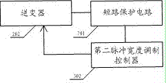
Fig. 7 shows according to a seventh embodiment of the invention, a kind of short-circuit protection principle block diagram of solar recharging system.Said short-circuit protection circuit 701 is connected with said second Pwm controller 203; Said short-circuit protection circuit 701 connects load voltage end (not shown); When load is excessive; Said short-circuit protection circuit 701 sends signal to said second Pwm controller 203, turn-offs the inverting output terminal of said inverter.
In one embodiment; The secondary output end of said inverter 203 utilizes constantan wire to be sample line; When load excessive on sample line sampling value greater than set point; Comprise a comparison amplifier in the said short-circuit protection circuit 701, turn-off said second Pwm controller 203 through said comparison amplifier output high potential.
It should be appreciated by those skilled in the art that those skilled in the art combine prior art and the foregoing description can realize said variant, do not repeat them here.Such variant does not influence flesh and blood of the present invention, does not repeat them here.
More than specific embodiment of the present invention is described.It will be appreciated that the present invention is not limited to above-mentioned specific implementations, equipment of wherein not describing in detail to the greatest extent and structure are construed as with the common mode in this area to be implemented; Those skilled in the art can make various distortion or modification within the scope of the claims, and this does not influence flesh and blood of the present invention.