CN102398417A - Image recording device and image recording method - Google Patents
Image recording device and image recording method Download PDFInfo
- Publication number
- CN102398417A CN102398417A CN2011102742464A CN201110274246A CN102398417A CN 102398417 A CN102398417 A CN 102398417A CN 2011102742464 A CN2011102742464 A CN 2011102742464A CN 201110274246 A CN201110274246 A CN 201110274246A CN 102398417 A CN102398417 A CN 102398417A
- Authority
- CN
- China
- Prior art keywords
- negative pressure
- pressure chamber
- pattern
- medium
- suction
- Prior art date
- Legal status (The legal status is an assumption and is not a legal conclusion. Google has not performed a legal analysis and makes no representation as to the accuracy of the status listed.)
- Pending
Links
Images


Classifications
-
- B—PERFORMING OPERATIONS; TRANSPORTING
- B41—PRINTING; LINING MACHINES; TYPEWRITERS; STAMPS
- B41J—TYPEWRITERS; SELECTIVE PRINTING MECHANISMS, i.e. MECHANISMS PRINTING OTHERWISE THAN FROM A FORME; CORRECTION OF TYPOGRAPHICAL ERRORS
- B41J11/00—Devices or arrangements of selective printing mechanisms, e.g. ink-jet printers or thermal printers, for supporting or handling copy material in sheet or web form
- B41J11/0085—Using suction for maintaining printing material flat
-
- B—PERFORMING OPERATIONS; TRANSPORTING
- B41—PRINTING; LINING MACHINES; TYPEWRITERS; STAMPS
- B41J—TYPEWRITERS; SELECTIVE PRINTING MECHANISMS, i.e. MECHANISMS PRINTING OTHERWISE THAN FROM A FORME; CORRECTION OF TYPOGRAPHICAL ERRORS
- B41J11/00—Devices or arrangements of selective printing mechanisms, e.g. ink-jet printers or thermal printers, for supporting or handling copy material in sheet or web form
- B41J11/02—Platens
- B41J11/06—Flat page-size platens or smaller flat platens having a greater size than line-size platens
Abstract
The present invention provides an image recording device and an image recording method, in order to shorten the required time for reducing the suction force on a medium. The image recording device includes a suction part and a control part. The suction part is configured to suction a medium on a medium support part via suction holes and has a negative pressure chamber communicating with the suction holes and at least two air-blowing parts whereby air inside the negative pressure chamber is discharged and negative pressure is generated in the negative pressure chamber, the air-blowing parts being attached at different positions on an outer surface of the negative pressure chamber. The control part is configured to switch between a first mode in which a suction force of the suction part on the medium is set to a first suction force and a second mode in which the suction force is set to a second suction force lower than the first suction force. The control part is configured to stop one of the air-blowing parts in the second mode.
Description
Technical field
The present invention relates to a kind of image recording structure and image recording process.
Background technology
In as ink-jet printer of an example of image recording structure etc.; Be provided with the platen (medium support) that as follows medium is supported; That is, make the medium of printed images become fixing attitude (for example, patent documentation 1) with respect to the head that sprays printing ink.
For example, a kind of following printer is arranged, that is, remain on fixing position in order when printing, to make the medium on the platen, thereby SS is set on platen, and medium is aspirated from SS.But,, then will hinder conveying if the suction force to medium is stronger when medium transport.The suction force that therefore, only need when medium transport, reduce medium gets final product.But if in order to reduce the suction force of medium and spended time, the then whole presswork time will be elongated.
Technical literature formerly
Patent documentation 1: japanese kokai publication hei 8-197799 communique
Summary of the invention
The present invention implements in light of this situation, and its purpose is that the suction force that shortens as far as possible medium reduces the needed time.
The main invention that is used to solve above-mentioned problem is a kind of image recording structure, it is characterized in that possessing: record portion, and it is document image on medium; Delivery section, it is carried said medium; The medium support, its utilization is provided with the bearing-surface of the peristome of SS, and said medium is supported; Suction section, to being aspirated by the said medium of said medium support part supports, said suction section has via said SS for it: negative pressure chamber, said negative pressure chamber is communicated with said SS; At least two air supplying part, said at least two air supplying part blow out the inner air of said negative pressure chamber, thereby make generation negative pressure said negative pressure chamber in, wherein, on the diverse location of the outer surface of said negative pressure chamber, said at least two air supplying part are installed; Control part, it switches the 1st pattern and the 2nd pattern, and when said the 2nd pattern; An air supplying part in said at least two air supplying part is stopped; Wherein, said the 1st pattern is said suction section to be made as the pattern of the 1st suction force to the suction force of said medium; Said the 2nd pattern is said suction force to be made as the pattern of the 2nd suction force that is lower than said the 1st suction force.
About further feature of the present invention, the record through this specification and accompanying drawing makes it clear and definite.
Description of drawings
Fig. 1 is the overall structure block diagram of printer.
Fig. 2 is the cutaway view of the summary of expression printer.
Fig. 3 A is used for figure that high suction mode is described, and Fig. 3 B is used for figure that low suction mode is described.
Fig. 4 A and Fig. 4 B are used for the figure that the pump unit to comparative example describes.
Fig. 5 A is used for the figure that the activity duration to a logger task of comparative example describes, and Fig. 5 B is used for the figure that the activity duration to the logger task of this embodiment describes.
Fig. 6 A and Fig. 6 B are used for the figure that the change example to printing action describes.
Symbol description
1 ... Printer;
1a ... The top;
2 ... Computer;
10 ... Controller;
11 ... Interface portion;
12…CPU;
13 ... Memory;
14 ... The unit controls circuit;
20 ... Supply unit;
21a, 21b ... Donor rollers;
22a, 22b ... Distributing roller;
23 ... Wind-up roll;
30 ... Record cell;
31 ... Platen;
311 ... Heater;
32 ... Balladeur train;
33 ... Head;
34 ... The top fan;
35 ... Lid mechanism;
40 ... Pump unit;
41 ... Negative pressure chamber;
42 ... The 1st fan;
43 ... The 2nd fan;
44 ... SS;
50 ... Detector sets;
51 ... Pressure sensor;
61,62,63 ... Fan.
The specific embodiment
According to the record of this specification and accompanying drawing, the item below clear and definite at least.
That is, a kind of image recording structure is characterized in that, possesses: record portion, and it is document image on medium; Delivery section, it is carried said medium; The bearing-surface that medium support, its utilization are provided with the peristome of SS supports said medium; Suction section, to being aspirated by the said medium of said medium support part supports, said suction section has via said SS for it: negative pressure chamber, said negative pressure chamber is communicated with said SS; At least two air supplying part, said at least two air supplying part blow out the inner air of said negative pressure chamber, thereby make generation negative pressure said negative pressure chamber in, wherein, on the diverse location of the outer surface of said negative pressure chamber, said at least two air supplying part are installed; Control part, it switches the 1st pattern and the 2nd pattern, and when said the 2nd pattern; An air supplying part in said at least two air supplying part is stopped; Wherein, said the 1st pattern is said suction section to be made as the pattern of the 1st suction force to the suction force of said medium; Said the 2nd pattern is said suction force to be made as the pattern of the 2nd suction force that is lower than said the 1st suction force.
According to this image recording structure, can shorten from the 1st pattern to the switching time of the 2nd pattern (suction force reduces the needed time).
In related image recording structure; From with said at least two air supplying part the air quantity that passes through of the peristome of the said negative pressure chamber that is communicated with of the suction inlet of an air supplying part, the air quantity that passes through greater than peristome from the said negative pressure chamber that is communicated with the suction inlet of another air supplying part.
According to this image recording structure, can enlarge the scope that produces negative pressure in the negative pressure chamber.Its result is further to strengthen or to weaken the suction force to medium.
In related image recording structure, said control part stops a said air supplying part when said the 2nd pattern.
According to this image recording structure, when the 2nd pattern, can further reduce the negative pressure of negative pressure chamber.Its result is further to weaken the suction force to medium.
In related image recording structure, array is equipped with two pressure fans at least in a said air supplying part.
According to this image recording structure, can increase the air quantity that passes through from the peristome of the negative pressure chamber that the suction inlet with an air supplying part is communicated with.
In related image recording structure, said control part switches to said the 2nd pattern from said the 1st pattern in by the action of said record portion to said medium enforcement image record.
According to this image recording structure, can shorten the whole record activity duration.
In related image recording structure, said at least two air supplying part directly or indirectly are installed on the said medium support.
According to this image recording structure,, therefore, for example can suppress vibration, and improve the precision of the bad inspection of ejection to the pedestal transmission of having loaded the medium support because an air supplying part is stopped.
Also have a kind of image recording process, it is characterized in that, use image recording structure and on medium document image, wherein, said image recording structure possesses: record portion, its document image on said medium; Delivery section, it is carried said medium; The bearing-surface that medium support, its utilization are provided with the peristome of SS supports said medium; Suction section, to being aspirated by the said medium of said medium support part supports, said suction section has via said SS for it: negative pressure chamber, said negative pressure chamber is communicated with said SS; At least two air supplying part, said at least two air supplying part blow out the inner air of said negative pressure chamber, thereby make generation negative pressure said negative pressure chamber in, wherein, on the diverse location of the outer surface of said negative pressure chamber, said at least two air supplying part are installed; Control part, it switches the 1st pattern and the 2nd pattern, and when said the 2nd pattern; An air supplying part in said at least two air supplying part is stopped; Wherein, said the 1st pattern is said suction section to be made as the pattern of the 1st suction force to the suction force of said medium; Said the 2nd pattern is said suction force to be made as the pattern of the 2nd suction force that is lower than said the 1st suction force.
According to this image recording process, can shorten from the 1st pattern to the switching time of the 2nd pattern (suction force reduces the needed time).
About printer
Below, as " image recording structure ", for example embodiment is described with ink-jet printer (below, be called printer).
Fig. 1 is the overall structure block diagram of printer 1.Fig. 2 is the cutaway view of the summary of expression printer 1.The printer 1 of this embodiment is gone up printed images at the roll web R (continuous paper) as medium.Medium is not limited to paper, for example also can be film or cloth.In addition, the printer 1 of this embodiment is connected with computer 2 with the mode that can communicate by letter, and computer 2 generates the printed data that is used to make printer 1 printed images.And the function of computer 2 also can be built in the printer 1.
Supply unit 20 (being equivalent to delivery section) does, along the transport path that is set in advance and with roll web R from the upstream side of throughput direction downstream side carry, and the part of roll web R is delivered to the member of printing zone.Supply unit 20 has: donor rollers 21a, 21b; Distributing roller 22a, 22b; Wind-up roll 23 etc. Donor rollers 21a, 21b and distributing roller 22a, 22b are made up of paired roller respectively, and the driven roller of a roller for being rotated through not shown motor, and the driven voller of another roller for being rotated with the driven roller interlock.When the image printing to the roll web R that is positioned at printing zone finishes; Through donor rollers 21a, 21b and distributing roller 22a, 22b etc.; Make position roll web R, that be printed with image be discharged from and be wound into drum, and position roll web R, that be not printed image as yet is supplied to printing zone through wind-up roll 23 from printing zone.
Record cell 30 (being equivalent to record portion) does, at the member that is positioned at printing (record) image on the roll web R of printing zone.The roll web R that is positioned at printing zone is supported by the upper surface of platen 31 (being equivalent to the medium support) from the rear side of an opposite side with printing surface.Record cell 30 has balladeur train 32 and 33 etc.Balladeur train 32 makes 33 on directions X (throughput direction of roll web R) and Y direction (width of roll web R), to move when being directed axle (not shown) guiding.33 for being used for the member to roll web R ejection printing ink, and 33 lower surface is provided with a plurality of nozzle Nz as printing ink ejection portion.And, can be the piezoelectricity mode from the printing ink of nozzle ejection mode, also can be the temperature-sensitive mode, wherein, said piezoelectricity mode is to apply voltage and make the balancing gate pit expand, shrink to driving element (piezoelectric element), thereby make the mode of printing ink ejection; Said temperature-sensitive mode does, uses heater element and makes and produce bubble nozzle in, and the mode that printing ink is sprayed through this bubble.
In platen 31 internal configurations a plurality of heaters 311 (for example nichrome wire) are arranged.Through making heater 311 energising, thereby the temperature of platen 31 rises, and then the temperature of the roll web R on the platen 31 (promptly, being positioned at the roll web R of printing zone) also rises.Its result does, can promote to spray the drying of the printing ink on the roll web R that drops on the platen 31, and can suppress on the printed images printing ink spread and sink in diffusing.For making heat be transmitted to the roll web R on the platen 31 equably, thereby with the mode in the whole zone that spreads all over platen 31 and dispose heater 311.
In addition, on the top 1a of the framework of printer 1, to be provided with a plurality of tops fan 34 with platen 31 opposed modes.Through from the roll web R air-supply of top fan 34 on platen 31, thus the drying that can promote to spray the printing ink on the roll web R that drops on the platen 31.
In addition, balladeur train 32 and 33 can be kept out of the way to the initial position of the throughput direction upstream side of printing zone.Be provided with lid mechanism 35 etc. in initial position.In printing stops, sealing through nozzle face, thereby can suppress printing ink evaporation from nozzle with lid mechanism 35 correct 33.
In addition, in the framework of printer 1, be provided with flat pedestal 1b, thereby framework inside is divided into two spaces.In the space of the upside of pedestal 1b, implement printing to the image of roll web R.Thus, 33 and balladeur train 32 be configured in the space of upside of pedestal 1b, and on pedestal 1b, be mounted with platen 31, negative pressure chamber 41, lid mechanism 35 etc.
Pump unit 40 (being equivalent to suction section) does, is used for the suction of the roll web R on the platen 31 and is adsorbed on the member on the bearing-surface of platen 31, and it has negative pressure chamber's the 41, the 1st fan the 42, the 2nd fan 43, SS 44 etc.On the bottom surface of platen 31, be connected with negative pressure chamber 41, and on the bottom surface of negative pressure chamber 41, the 1st fan 42 and the 2nd fan 43 be installed with the mode of on throughput direction, arranging.In addition, the 2nd fan 43 is made up of two fan 43a, 43b, and at the downside (ejection oral-lateral) of a fan 43a another fan 43b is installed.And; On platen 31, be formed with SS 44 as the hole of on above-below direction, running through; And a peristome of SS 44 is set on the bearing-surface of platen 31, and another peristome of SS 44 is set on the bottom surface (joint face of platen 31 and negative pressure chamber 41) of platen 31.That is, negative pressure chamber 41 is communicated with outside (top of platen 31) via SS 44.In addition, platen 31 utilizes the bearing-surface of the peristome that is provided with SS 44 that roll web R is supported.
The 1st fan 42 and the 2nd fan 43 are discharged (that is, the air of the inside of negative pressure chamber 41 being aspirated) with the air of the inside of negative pressure chamber 41 to the outside, thereby make the inside of negative pressure chamber 41 become negative pressure state.At this moment, the extraneous gas on the bearing-surface of platen 31 is sucked up to the inside of negative pressure chamber 41 via SS 44, thereby the roll web R on the platen 31 is aspirated and is adsorbed on the bearing-surface of platen 31.That is, pump unit 40 passes through two fans 42,43, and via SS 44 the roll web R that is supported by platen 31 is aspirated.
In press, aspirate and be adsorbed on the bearing-surface of platen 31 through making the roll web R on the platen 31, thereby can be maintained at preposition, and then the droplets of ink spray is fallen on the correct position at the bearing-surface coiling paper R of platen 31.In addition, even roll web R because of the moisture of droplets of ink swelling has taken place, also can roll web R be remained smooth state.
In the printer 1 of this structure, controller 10 make 33 with balladeur train 32 1 arise from move on directions X and the Y direction in, at the image (being equivalent to operation of recording) that is being positioned at printing two dimension on the roll web R of printing zone.Afterwards, controller 10 makes supply unit 20 that position roll web R, that be printed with image is discharged to outside the printing zone, and position roll web R, that be not printed image as yet is supplied to printing zone (being equivalent to carry action).That is to say that printing action and the conveying action of roll web R of controller 10 (being equivalent to control part) through making image carried out repeatedly, thereby prints a plurality of images along the continuous direction of roll web R.
About service action
Moisture in the printing ink is easy to meniscus (Free Surface that the exposes printing ink externally) evaporation from nozzle, and because evaporation can cause the viscosity of printing ink to rise.If the viscosity of printing ink increases, it is bad then can to produce ejection should when nozzle sprays printing ink, spraying the printing ink of ormal weight.In addition, owing to sneaked into atmosphere, perhaps be attached with foreign matter, also can cause the generation ejection bad at nozzle from the meniscus of nozzle.When the generation ejection was bad on nozzle, the image quality of printed images will deterioration.
Therefore, in the printer 1 of this embodiment, implement service action termly." service action " be meant, " spraying bad inspection " that having or not of the nozzle (bad nozzle) that produces the ejection bad phenomenon checked and carry out " cleaning action " in order normally to spray printing ink from bad nozzle.And, in service action, for example, both can be employed in to carry out only when detecting bad nozzle, to carry out after the bad inspection of ejection and clean action, also can carry out repeatedly and clean action and spray bad inspection till no longer detecting bad nozzle.
Spray bad inspection
The bad inspection unit of the ejection of this embodiment (not shown) has the detection of high potential with electrode and printing ink recoverer etc., and in the printing ink recoverer, is mounted with to detect and uses electrode.The lid mechanism 35 that sprays bad inspection unit and Fig. 2 likewise is loaded in initial position on the pedestal 1b of printer 1.33 nozzle face (nozzle plate, the tabular parts with electric conductivity) is grounded, and is lower than the current potential (earthing potential) that detects with electrode thereby become, and in addition, the solvent of printing ink is the liquid (for example, water) with electric conductivity.Therefore, the printing ink that is ejected from nozzle has earthing potential.
When spraying bad inspection, at first, make 33 to keep out of the way initial position.And, make 33 (nozzle plate) and detection opposed with the state that separates predetermined interval, and (continuity ground) make printing ink from the nozzle ejection as the inspection object with electrode.And, according to because of the ejection of printing ink is detecting the electric property variation (potential change) that produces with electrode side, come whether droplets of ink normally be ejected from the nozzle as detected object and judge.For example will detect with the electric property variation that produces on the electrode and obtain as voltage signal; If the peak swing of voltage signal is greater than threshold value; Then being judged as printing ink normally is ejected from nozzle; And if the peak swing of voltage signal then is judged as printing ink and fails normally to be ejected from nozzle below threshold value.And, owing to reclaimed by the printing ink recoverer towards the printing ink that detects with the electrode ejection from nozzle, thereby can prevent the pollution in the printer 1.And the method that sprays bad inspection is not limited thereto, and also can adopt other method.
Clean action
In this embodiment, implement flushing, pump suction, wiping etc. as cleaning action.When implement cleaning action, also when spraying bad inspection likewise, make 33 to keep out of the way to initial position.
" flushing " be meant, make 33 with the opposed state of printing ink recoverer (not shown) under, forcibly from nozzle ejection printing ink, thereby make printing ink that viscosity increased and the action that sprays with printing ink attached to the foreign matter on the nozzle face.
" pump suction " is meant; Through 33 nozzle face and printing ink recoverer are close together; And carry out pump suction (not shown) via the flexible pipe of the bottom surface that is connected in the printing ink recoverer, thereby the action that printing ink that the printing ink in correct 33 has increased together with viscosity and foreign matter aspirate.
" wiping " be meant, thereby with the wiper of rubber system etc. nozzle face is carried out the action that foreign matter etc. is removed in wiping.
High suction mode, low suction mode
Fig. 3 A is used for figure that high suction mode is described, and Fig. 3 B is used for figure that low suction mode is described.As indicated above, the printer 1 of this embodiment has pump unit 40, and said pump unit 40 aspirates the roll web R that is supported by platen 31 via SS 44, and has: negative pressure chamber 41, this negative pressure chamber 41 are communicated with SS 44; The 1st fan 42 and the 2nd fan 43, the 1 fans 42 and the 2nd fan 43 blow out the air of the inside of negative pressure chamber 41, produce negative pressure in the negative pressure chamber 41 thereby make.And, on the upper surface 41c of negative pressure chamber 41, also be provided with a plurality of holes, and the hole that is set on the upper surface 41c of negative pressure chamber 41 is communicated with the SS 44 that is set on the platen 31.In addition, at this, " the 1st fan 42 and the 2nd fan 43 " is equivalent to " two air supplying part ", is that example describes as " pressure fan " with " (axial flow) fan ".
In the image printing action to roll web R; For the roll web R on the platen 31 is remained on preposition; Even and in order also roll web R to be remained smooth state under the situation that causes roll web R generation swelling at the moisture because of printing ink, the suction absorption affinity of enhancing thereby hope is tried one's best to the roll web R on the bearing-surface of platen 31.In the printing action; Keep smooth state through roll web R being aspirated securely and being adsorbed on the bearing-surface of platen 31; Thereby the heat of platen 31 (heater 311) will be passed on the roll web R on the platen 31; Thereby can promote the drying of printing ink, thereby can prevent that spreading and sinking in of image is diffusing.In addition, droplets of ink spray is dropped on the correct position of roll web R, and can prevent the contact between roll web R and 33.That is, in printing action, through the roll web R on the platen 31 being remained on preposition, thereby can suppress the image quality deterioration of printed images with smooth state.
On the other hand, in the conveying of roll web R,, need to weaken the degree that does not relax to roll web R to the suction absorption affinity of the roll web R on the bearing-surface of platen 31 as far as possible for fear of becoming for the bigger resistance of carrying.
That is, in carrying action, and compare in the printing action, hope to reduce the suction force of the roll web R on 40 pairs of platens 31 of pump unit.In this way, move according to handling, thus will be different to the suitable suction force of the roll web R on the platen 31.
Therefore; In the printer 1 of this embodiment; Can switch " high suction mode (being equivalent to the 1st pattern) " and " low suction mode (being equivalent to the 2nd pattern) " through controller 10; Wherein, said " high suction mode (being equivalent to the 1st pattern) " do, the suction force of 40 couples of roll web R of pump unit is made as the higher suction force pattern of (being equivalent to the 1st suction force); And said " low suction mode (being equivalent to the 2nd pattern) " is the suction force of 40 couples of roll web R of pump unit to be made as the pattern of the suction force (being equivalent to the 2nd suction force) that is lower than the suction force in the high suction mode.
And controller 10 is set at high suction mode in the printing action, and in the conveying to roll web R, is set at low suction mode.Through adopting this mode, can in the printing action, the roll web R on the platen 31 be remained on the preposition place with smooth state, thereby can prevent the image quality deterioration of printed images.On the other hand, in conveying, can weaken suction absorption affinity, thereby successfully carry the roll web R on the bearing-surface of platen 31 to roll web R.Conversely speaking, through in conveying, being set at low suction mode, thereby can reduce the driving force (for example, the traction force of distributing roller 22a, 22b) of supply unit 20 to roll web R.
In order to change the suction force to the roll web R on the platen 31, the negative pressure that only needs to change in the negative pressure chamber 41 gets final product.Through improving the negative pressure (through reducing pressure) in the negative pressure chamber 41; Thereby can improve suction force to the roll web R on the platen 31; And through the negative pressure in the reduction negative pressure chamber 41 (through improving pressure), thereby can reduce suction force to the roll web R on the platen 31.That is, the printer 1 of this embodiment also can be described as a kind of can be to the negative pressure in the negative pressure chamber 41 being made as the pattern of high negative and the negative pressure in the negative pressure chamber 41 being made as the printer that switches than the pattern of lower negative pressure.
But when after the printing release, switching to low suction mode from high suction mode, when implementing the conveying action of roll web R afterwards again, if longer to the switching time of low suction mode from high suction mode, the then whole presswork time will be elongated.In addition; In order to shorten the whole presswork time; In printing action from high suction mode when low suction mode switches, if longer to the switching time of low suction mode from high suction mode, the time that then in printing is moved, is not in high suction mode is with elongated.
So in this embodiment, its purpose is, shortens from high suction mode to the switching time (that is, the suction force to roll web R reduces the needed time) of hanging down suction mode as far as possible.
Therefore; In the printer 1 of this embodiment; The 1st fan 42 and the 2nd fan 43 (axle of two fans 42,43 is positioned on the same axle, but two fans 42,43 are installed abreast) are installed at the diverse location place of the bottom surface of negative pressure chamber 41 41a.And controller 10 stops a fan 43 in two fans 42,43 when hanging down suction mode.
Particularly, when high suction mode, shown in Fig. 3 A, the both sides of the 1st fan 42 and the 2nd fan 43 are all placed opening.At this moment, through two fans 42,43, and the air in the negative pressure chamber 41 is blown out to the outside.On the other hand, when hanging down suction mode, shown in Fig. 3 B, the 1st fan 42 is placed opening, and the 2nd fan 43 is placed closed condition (stopping).At this moment, the air in the negative pressure chamber 41 is blown out to the outside, and make in the negative pressure chamber 41 by atmosphere opening through the 2nd fan 43 through the 1st fan 42.Therefore, air outside is sucked in the negative pressure chamber 41 from the 2nd fan 43.More specifically, the peristome 41e of the negative pressure chamber 41 that air outside is communicated with through the suction inlet with the 2nd fan 43, and be sucked in the negative pressure chamber 41.Its result is that the negative pressure in the negative pressure chamber 41 will reduce (pressure rising) immediately, thereby can promptly carry out from the switching of high suction mode to low suction mode.
Promptly; According to the printer 1 of this embodiment (perhaps; Printing process according to the printer that has adopted this embodiment 1), owing to when hanging down suction mode, the 2nd fan 43 is stopped, and with the 2nd fan 43 (strictly speaking; Be the peristome 41e of the negative pressure chamber 41 that is communicated with the suction inlet of the 2nd fan 43) utilize as " airport ", therefore can shorten from the switching time of high suction mode to low suction mode.
Its result does, for example in printing action back from high suction mode when low suction mode switches, can shorten the presswork time of integral body.On the other hand, in printing action from high suction mode when low suction mode switches, can prolong the time that printing is in high suction mode in moving.
In addition, in low suction mode, the 2nd fan 43 of the generation through will in high suction mode, being used for high negative pressure utilizes as airport, thereby need not to be provided with in addition airport (for example, automatic opening and closing window), thereby can the simplification device structure.
In addition, owing to when low suction mode, a fan 43 in two fans 42,43 is stopped, thereby compare during with high suction mode, can reduce noise and vibration, in addition, can suppress power consumption.
In the printer 1 of this embodiment, for a fan 43 in two fans 42,43 is stopped and with it as airport, thereby two fans 42,43 are installed in the negative pressure chamber 41 with side by side mode.When two fans are installed with mode side by side,, air quantity can change hardly though increasing static pressure.
Therefore be set at, from two fans installing side by side the air quantity (m that passes through of the suction inlet peristome that be communicated with, negative pressure chamber 41 of a fan
3/ h), greater than the air quantity (m that passes through from peristome that be communicated with the suction inlet of another fan, negative pressure chamber 41
3/ h).In other words, a fan in two fans installing with mode side by side makes the negative pressure that produce in the negative pressure chamber 41, is higher than another fan and makes the negative pressure that produce in the negative pressure chamber 41.
Therefore; In the printer 1 of this embodiment; With mode side by side the 1st fan 42 and the 2nd fan 43 are installed; Wherein, the 1st fan 42 is made up of a fan, and the 2nd fan 43 in upright arrangement installations (mode that is positioned on the same axle with two fans is installed) have two fans.Two fans are installed and it is turned round through array, thereby compare, can improve static pressure with the situation that a fan with identical characteristics is turned round.That is, compare with the air blown out negative pressure chamber 41 by a fan (the 1st fan 42) in, the air that two fans (the 2nd fan 43) of being installed by array blow out in the negative pressure chamber 41 can make generation high negative in the negative pressure chamber 41.
Promptly; In the printer 1 of this embodiment; Through the 1st fan 42 being installed with mode side by side and being compared the 2nd higher fan 43 of static pressure characteristic with the 1st fan 42, thereby can make air quantity Q2 greater than air quantity Q1, wherein; Said air quantity Q2 does; From the air quantity that the peristome 41e of the negative pressure chamber 41 that the suction inlet with the 2nd fan 43 (being equivalent to an air supplying part) is communicated with passes through, said air quantity Q1 does, the air quantity that passes through from the peristome 41d of the negative pressure chamber 41 that the suction inlet with the 1st fan 42 (being equivalent to another air supplying part) is communicated with.
In this way; Thereby under high suction mode, can make the negative pressure in the negative pressure chamber 41 higher through bigger the 2nd fan 43 (that is the 2nd higher fan 43 of maximum static pressure characteristic) of air quantity Q2; And under low suction mode; Can make the negative pressure in the negative pressure chamber 41 lower through less the 1st fan 42 (that is, the 1st fan 42 that the maximum static pressure characteristic is lower) of air quantity Q1, wherein; The air quantity that said air quantity Q2 passes through for the peristome 41e from negative pressure chamber 41, the air quantity that said air quantity Q1 passes through for the peristome 41d from negative pressure chamber 41.That is, can enlarge the scope of the negative pressure that in negative pressure chamber 41, is produced, and can be when high suction mode (for example; During the printing action), negative pressure chamber 41 is built in required high negative pressure, and can be when hanging down suction mode (for example; When carrying action), negative pressure chamber 41 is built in required lower negative pressure.
In addition, through a lower fan of static pressure characteristic and a higher fan of static pressure characteristic are installed with mode side by side, also can make the air quantity that passes through from the peristome of the negative pressure chamber 41 that is communicated with the suction inlet of each fan different.But, when high suction mode, negative pressure chamber 41 is built in the higher fan of this static pressure characteristic of required high negative pressure, be large-scale fan, thereby cost can increase also.
In addition, when identical two fans of static pressure characteristic are installed with mode side by side, also can be different each other through the revolution that makes fan, thus make the air quantity that passes through from the peristome of the negative pressure chamber 41 that is communicated with the suction inlet of each fan different each other.But, only depend on the revolution of regulating fan, for being produced, the air quantity that passes through from the peristome of negative pressure chamber 41 has restriction for the difference.So the Negative Pressure Difference in the negative pressure chamber 41 under high suction mode and the low suction mode diminishes, thereby is difficult to being set at needed negative pressure in the negative pressure chamber 41.
Therefore, as this embodiment, a fan in two fans 42,43 (the 2nd fan 43) is set at the structure that array is equipped with two fans gets final product.Through adopting this kind mode, can be in the miniaturization of implement device, cost-savingization, make the air quantity that passes through from the peristome of the negative pressure chamber 41 that is communicated with the suction inlet of each fan of installing side by side different.Its result is to enlarge the scope of the negative pressure that in negative pressure chamber 41, is produced.And in the 2nd fan 43, the quantity of mounted fan in upright arrangement also can be for more than two.
In addition; Even when low suction mode, make under the situation that the 1st lower fan 42 of maximum static pressure characteristic stops; Owing to the 1st fan 42 plays a role as airport; Thereby compare when being the high suction mode of opening with two fans 42,43, low suction mode also can reduce the negative pressure in the negative pressure chamber 41.But; As this embodiment; Through make when the low suction mode the 2nd bigger fan 43 of the air quantity Q2 that passes through from the peristome 41e of negative pressure chamber 41 (; The 2nd fan 43 that the maximum static pressure characteristic is higher) stops, thereby can reduce the negative pressure in the negative pressure chamber 41 under the low suction mode more.Its result is can weaken the suction absorption affinity to the roll web R on the bearing-surface of platen 31, thereby can for example successfully carry, or the driving force of supply unit 20 is reduced.
And; Pressure (negative pressure) in the negative pressure chamber 41 under high suction mode and the low suction mode; Only need set and get final product according to the driving force of supply unit 20 and the kind of roll web R etc.; For example, the pressure in the negative pressure chamber in the high suction mode 41 are set at the pressure that forces down 805Pa than atmosphere, and will hang down pressure in the negative pressure chamber 41 in the suction mode and be set at the pressure that forces down 140Pa than atmosphere and get final product.In addition, can pass through to regulate the revolution of fan 42,43, thereby the negative pressure in the negative pressure chamber 41 are adjusted to required negative pressure.In addition, the pressure sensor 51 that the pressure to the air in the negative pressure chamber 41 detects can be set in negative pressure chamber 41 also, and whether controller 10 is that required pressure (negative pressure) is confirmed to the pressure in the negative pressure chamber 41 for example.
Fig. 4 A and Fig. 4 B do, is used for the figure that the pump unit to comparative example describes.
Shown in Fig. 4 A; Also can be through two fans 61,62 of installation in upright arrangement; And when high suction mode, two fans 61,62 are placed opening; When hanging down suction mode, a fan 61 in two fans 61,62 is placed closed condition, thereby the negative pressure in the negative pressure chamber in each suction mode 41 are set at required negative pressure.
In addition, shown in Fig. 4 B, also can pass through a higher fan 63 of maximum static pressure characteristic is installed, and revolution is controlled, thereby the negative pressure in the negative pressure chamber in each suction mode 41 are set at required negative pressure.
But; Shown in comparative example (Fig. 4 A, Fig. 4 B); When on the same position (position) only fan being installed at the outer surface of negative pressure chamber 41; Then under low suction mode, can't as this embodiment (Fig. 3 B), a fan 43 in two fans 42,43 be utilized as airport.Therefore, compare, in the pump unit of comparative example, will spend the more time to the switching of low suction mode from high suction mode with the pump unit 40 of this embodiment.
Therefore, in this embodiment, two fans 42,43 are installed at the diverse location of the outer surface of negative pressure chamber 41.More specifically, on the diverse location in the outer surface of negative pressure chamber 41, the face except the upper surface 41c that is provided with the hole that is communicated with SS 44 (bottom surface 41a and side 41b), two fans 42,43 are installed.Though in this embodiment, two fans 42,43 of having given an example are installed in the example on the bottom surface 41a of negative pressure chamber 41, are not limited thereto, and also can two fans 42,43 be installed on the side 41b of negative pressure chamber 41.
In addition; Only needing in negative pressure chamber 41, to install at least two fans gets final product; Under the situation that the fan more than three is installed, also can be through (at least) fan being stopped when the low suction mode, thus the fan that will stop utilizing as airport.Its result is can shorten from high suction mode to the switching time of hanging down suction mode.In addition, also can adopt with side by side mode and the fan (that is the 2nd fan 43) that two, array are equipped with two fans is installed.At this moment; As long as under high suction mode, place opening (promptly two fans; Four fans are placed opening); And in low suction mode, a fan is stopped, and an only fan that will belong in two fans of another fan places opening get final product (that is, need only three fans are placed closed condition).
In addition, in above-mentioned service action (in the bad inspection of ejection, clean in the action), need not in the picture printing action enhancing to the suction absorption affinity of the roll web R on the bearing-surface of platen 31.Therefore, in service action, be set at low suction mode and get final product.Through this kind mode, can reduce noise and vibration, in addition, can suppress power consumption.
Especially, as shown in Figure 2 in the printer 1 of this embodiment, two fans 42,43 are installed on the platen 31 via negative pressure chamber 41 indirectly.Therefore, the vibration that is produced by fan 42,43 also is easy to the pedestal 1b via the printer 1 that is mounted with negative pressure chamber 41 and platen 31, is loaded on the bad inspection unit of ejection (not shown) on the pedestal 1b and be passed at initial position.In addition, when the mode with the above-mentioned bad inspection of ejection, and bad when judging to spraying, the vibration of fan 42,43 will become noise source according to the electric property variation that on detecting with electrode, is produced.Therefore, in service action, through being set at low suction mode, and a fan 43 in two fans 42,43 is stopped, thereby can reduce vibration.Its result is can reduce the noise when ejection is bad to be checked, thereby can improve the precision of the bad inspection of ejection.
In addition, also can adopt two fans 42,43 directly to be installed in the structure on the platen 31.In addition, in order to reduce the vibration of fan 42,43, also can be, padded coaming is set between 43 at negative pressure chamber 41 and fan 42.In addition,, be not limited thereto, also can the upper surface 41c of negative pressure chamber 41 be used as platen 31 though in the printer 1 of this embodiment, make platen 31 and negative pressure chamber 41 be various parts.
The printing action
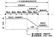
Fig. 5 A does, is used for the figure that the activity duration to a logger task of comparative example describes, and Fig. 5 B does, is used for the figure that the activity duration to the logger task of this embodiment describes.At this, till moving from the conveying that is transported to printing zone to the printing action of the roll web R printed images that is positioned at printing zone, to new position, be called a logger task with roll web R.In addition, with 33 with respect to the roll web R that is positioned at printing zone and directions X (throughput direction of roll web) go up move in, be called " print cycle " to the action of roll web R ejection printing ink.Make 33 to go up the action of moving through between print cycle, carrying out, thereby on roll web R, to print out the image of two dimension in Y direction (width of roll web R).Below, give an example through six times print cycle and the example that the roll web R that is positioned at printing zone accomplishes the printing of image is described.And, accomplish the print cycle number of image printing, change according to the size and the printed resolution of image.
In comparative example (Fig. 5 A); The controller 10 of printer 1 during whole printing action always (during whole six print cycle always) keep the state of high suction mode; And after the printing action, carry out the change action that switches to low suction mode from high suction mode.Afterwards, from high suction mode after low suction mode switches fully, controller 10 is carried out and is carried action.That is, the activity duration of a logger task in the comparative example is print the total time of action required time, change action required time and conveying action required time, thereby the activity duration of a logger task to be longer relatively.
Of preamble, in the printer 1 of this embodiment, when hanging down suction mode, a fan 43 in two fans 42,43 that in negative pressure chamber 41, produce negative pressure is stopped, and the fan after will stopping 43 utilizing as airport.Thus, shorten from high suction mode to the switching time of hanging down suction mode.Yet though shortened the time of change action, as comparative example (Fig. 5 A), spended time also is inefficent if be merely the change action of the action beyond the conduct printing.
For this reason, in this embodiment, be purpose to shorten the whole presswork time as far as possible.
Therefore; In the printer 1 of this embodiment (Fig. 5 B); In the previous action of carrying action, i.e. in the printing action; Controller 10 stops through making a fan 43 in two fans 42,43, thereby carries out from the switching (in other words, pressure negative pressure chamber 41 in from high negative pressure to lower negative pressure switched) of high suction mode to low suction mode.
According to this printer 1 (perhaps; The printing process of being implemented according to this printer 1), owing to implement change action concurrently, therefore can not spend the time that only is used for change action with the printing action; Thereby compare with comparative example, can shorten the whole presswork time.Particularly; The activity duration of a logger task in this embodiment does; Printing needed time of action and the total time of carrying the needed time of action; And compare with the activity duration of a logger task in the comparative example, can only shorten amount corresponding to the change action required time.
In addition; Not only through to the unlatching of fan 42,43, close and control, also through the revolution of fan 42 is controlled, thus can be with being set at required negative pressure in the negative pressure chamber 41; Its result is can the suction force to roll web R be set at required suction force.For example, in this embodiment, under high suction mode; Through two fans 42,43 are turned round with 100% revolution together; Thereby negative pressure chamber 41 is built in required high negative pressure (required high suction force), and under low suction mode, stops (being made as 0% revolution) through making the 2nd fan 43; And the 1st fan 42 is turned round with 65% revolution, thereby negative pressure chamber 41 is built in required lower negative pressure (required low suction force).
Therefore; Controller 10 is from high suction mode during to the switching of low suction mode (during beginning at change action, Fig. 5 B T0); The 2nd fan 43 is stopped, and the revolution of the 1st fan 42 is set at and hangs down the corresponding revolution of suction force in the suction mode (be 65% revolution) here.Through adopting this mode, can with simple control make pressure in the negative pressure chamber 41 from high negative pressure to lower negative pressure conversion stably.
In addition, in this embodiment, controller 10 begins from the change action of high suction mode to low suction mode in the second half of printing action.For example, shown in Fig. 5 B, when accomplishing the printing of image through six times print cycle, controller 10 switches to low suction mode from high suction mode after four print cycle.And, both can between print cycle, carry out to the switching of low suction mode from high suction mode, also can midway carrying out in print cycle.Its result is in the printing action, can prolong the time that is in high suction mode.Through adopting this kind mode; Can be in the long period in the printing action; Roll web R on the platen 31 is remained on the preposition place with smooth state, thus can suppress printed images the image quality deterioration (can prevent that spreading and sinking in of printing ink from loosing and with 33 between contact etc.).
And; In this embodiment; Controller 10 begins from the change action of high suction mode to low suction mode at time point (T0), and wherein, said time point (T0) does; From the deadline point (T1 of Fig. 5 B) of printing action, needed time of inverse operation change action (ta second) and the time point of acquisition.In Fig. 5 B,, thereby, begin change action at the time started of the 5th print cycle point owing to the needed time of change action (ta second) is equivalent to the printing time of twice print cycle.In addition; Though enumerated the example of accomplishing the printing of image with six times print cycle at this; But for example when accomplishing the printing of image, only need to get final product, in addition at the time started of the 3rd print cycle point beginning change action with four times print cycle; When accomplishing the printing of image, only need to get final product at the time started of the 15 print cycle point beginning change action with 16 times print cycle.Its result is in the printing action, further to prolong the time that is in high suction mode.Through adopting this kind mode, can in the longer time in the printing action, the roll web R on the platen 31 be remained on the preposition place with smooth state, thereby suppress the image quality deterioration of printed images.
And from the change action needed time (ta second) of high suction mode to low suction mode, (by each printer 1) determines to get final product when (by the kind of each printer 1), the manufacturing at printer 1 when the design of printer 1.But the needed time of change action can produce error sometimes.Therefore; In order to make it to have property more than needed; Also can begin change action at following time point; Said time point does, from total time (ta+ α) of deadline point (T1 of Fig. 5 B), needed time of inverse operation change action (ta second) and the error time (α) of printing action and the time point of acquisition.Through adopting this kind mode, can switched to effectively under the state of low suction mode from high suction mode, carry out and carry action.
In addition, after the printing action, regularly carry out service action (spray bad inspection, clean action) sometimes.As indicated above, when carrying out service action, through being set at low suction mode, vibrate and noise, and then can improve the precision of the bad inspection of ejection thereby can reduce.Therefore, through as this embodiment, in printing action, switching to low suction mode, thereby can, the printing action carry out service action immediately after accomplishing from high suction mode.Therefore, can shorten the whole presswork time.
Change example
Fig. 6 A and Fig. 6 B are to be used for the figure that the change example that printing is moved is described.In described embodiment (Fig. 5 B), though illustration after printing action, carry out the example of carrying action immediately, be not limited thereto.After the printing action, regularly carry out service action sometimes, carry out again afterwards and carry action.In addition, a kind of printer 1 that can set " stand-by time " is arranged, said " stand-by time " do, after printing action repeatedly, and perhaps after all printing actions, the time of not carrying out any action.In this printer 1, after the printing action, be provided with stand-by time, and after the stand-by time process, carry out and carry action.
Therefore; In changing example, shown in Fig. 6 A, controller 10 is not in the printing action, to switch to low suction mode from high suction mode; But, switch to low suction mode from high suction mode in " in the service action " or " in the stand-by time " as the previous action of carrying action.Through adopting this kind mode, can in the printing action, be set at and be in high suction mode always, thereby can the roll web R on the platen 31 be remained on the preposition place with smooth state, and then can suppress the image quality deterioration of printed images.In addition, and after printing action, carry out change action, the situation of service action or stand-by time of carrying out is again afterwards compared, and can shorten the presswork time of integral body.That is, owing to parallel mode is carried out change action, so efficient is better with the action (service action, stand-by time) with other.And, though in Fig. 6 A, with the beginning of service action or stand-by time in carry out change action, be not limited thereto, for example, also can be at the second half execution change action of service action or stand-by time.
In addition; Though in said embodiment (Fig. 5 B); Carrying out from high suction mode during when beginning (at change action) to the switching of low suction mode; The 2nd fan 43 is stopped, and the revolution of the 1st fan 42 is set at and hangs down the corresponding revolution of suction force (65% revolution) in the suction mode, but be not limited thereto.
For example; Also can adopt following mode, that is, and shown in Fig. 6 B; Controller 10 is from high suction mode during to the switching of low suction mode (T2 during beginning at change action, Fig. 6 B); Make two fans 42,43 stop (placing closed condition), and through the scheduled time (tc second) (at the T3 time point) afterwards, the revolution of the 1st fan 42 is set at and hangs down the corresponding revolution of suction force (65% revolution) in the suction mode.
Through adopting this kind mode, just after low suction mode switches (T2~T3), make two fans, 42,43 places by atmosphere opening, thus the negative pressure of negative pressure chamber 41 is more promptly descended (can improve pressure).That is,, two fans 42,43 (strictly speaking, being peristome 41d, the 41e of the negative pressure chamber 41 that is communicated with each suction inlet of two fans 42,43) are played a role as airport just after low suction mode switches.And, through (T3) after the scheduled time, through making the 1st fan 42, thereby can the negative pressure in the negative pressure chamber 41 be placed and hang down the corresponding lower negative pressure of suction mode with 65% revolution running.
The needed time of change action (the tb second among Fig. 6 B) that this changes example, can be set at the needed time of the change action that is shorter than said embodiment (the ta second among Fig. 5 B).Therefore, in the previous action of carrying action, can prolong the time that is in high suction mode.If the previous action of carrying action then can remain on the preposition place with smooth state with roll web R, thereby can suppress the image quality deterioration of printed images for the printing action in the longer time.But the control of said embodiment (Fig. 5 B) is more easy, and more stable to the conversion of low suction mode from high suction mode.
In addition, though in described embodiment (Fig. 5 B), in the previous action of carrying action, switch to low suction mode, be not limited thereto from high suction mode.Also can shown in comparative example (Fig. 5 A), after the previous release of carrying action, switch to low suction mode from high suction mode.In this case, if the previous action of conveying action is the printing action, then during moving, keeps the state of high suction mode always, thereby can suppress the image quality deterioration of printed images in whole printing.In addition; Owing to set the time that only is used for change action in this case; Therefore thisly in low suction mode, stop a fan 43 in two fans 42,43; And the fan that will stop 43 being as airport, and then to shorten from the invention of high suction mode to the switching time of low suction mode be comparatively effective.
Other embodiment
Though this embodiment is mainly narrated image recording structure, also comprise disclosing of image recording process etc.And this embodiment does, makes the understandable embodiment of the present invention, rather than is used for embodiment that the present invention is limited and explains.The present invention can change and improve under the condition that does not break away from aim of the present invention, and obviously also comprises its equivalent in the present invention.Especially, the embodiment of being narrated hereinafter also is included in the present invention.
About printer
Though in described embodiment, enumerate out a kind ofly making 33, be not limited thereto at the printer 1 of printed images with respect to the roll web R that is positioned at printing zone and when on the throughput direction of roll web R and width, moving.For example, also can be employed in roll web R from 33 the below that is fixed through the time printed images printer.
In addition, the medium that is used for document image is not limited to roll web R, also can adopt single-sheet stationery, also can adopt through the image recording structure of document image from other fluid beyond the nozzle ejection printing ink and on medium.
In addition; Image recording structure is not limited to printer; For example; Also can use on the various devices of ink-jet technologies, use the technology identical with above-mentioned embodiment at colour filter manufacturing installation, dyeing apparatus, micromachining device, semiconductor-fabricating device, Surface Machining device, three-dimensional modeling machine, gas vaporization device, organic EL manufacturing installation (particularly macromolecule EL manufacturing installation), display manufacturing apparatus, film formation device, DNA chip manufacturing device etc.In addition, these methods and manufacturing approach are also in the category of range of application.
Claims (7)
1. image recording structure is characterized in that possessing:
Record portion, it is document image on medium;
Delivery section, it is carried said medium;
The medium support, its utilization is provided with the bearing-surface of the peristome of SS, and said medium is supported;
Suction section, it, and has being aspirated by the said medium of said medium support part supports via said SS: negative pressure chamber, said negative pressure chamber is communicated with said SS; At least two air supplying part, said at least two air supplying part blow out the inner air of said negative pressure chamber, thereby make generation negative pressure said negative pressure chamber in, wherein, on the diverse location of the outer surface of said negative pressure chamber, said at least two air supplying part are installed;
Control part, it switches the 1st pattern and the 2nd pattern, and when said the 2nd pattern; An air supplying part in said at least two air supplying part is stopped; Wherein, said the 1st pattern is said suction section to be made as the pattern of the 1st suction force to the suction force of said medium; Said the 2nd pattern is said suction force to be made as the pattern of the 2nd suction force that is lower than said the 1st suction force.
2. image recording structure as claimed in claim 1, wherein,
From with said at least two air supplying part the air quantity that passes through of the suction inlet peristome that be communicated with, said negative pressure chamber of an air supplying part, greater than air quantity from passing through with the suction inlet of another air supplying part peristome that be communicated with, said negative pressure chamber.
3. image recording structure as claimed in claim 2, wherein,
Said control part stops a said air supplying part when said the 2nd pattern.
4. like claim 2 or 3 described image recording structures, wherein,
In the said air supplying part, array is equipped with two pressure fans at least.
5. like each described image recording structure in the claim 1 to 4, wherein,
Said control part switches to said the 2nd pattern from said the 1st pattern in by the action of said record portion to said medium enforcement image record.
6. like each described image recording structure in the claim 1 to 5, wherein,
Said at least two air supplying part directly perhaps are installed on the said medium support indirectly.
7. an image recording process is characterized in that,
Use image recording structure and on medium document image, wherein, said image recording structure possesses:
Record portion, it is document image on said medium;
Delivery section, it is carried said medium;
The medium support, its utilization is provided with the bearing-surface of the peristome of SS, and said medium is supported;
Suction section, to being aspirated by the said medium of said medium support part supports, said suction section has via said SS for it: negative pressure chamber, said negative pressure chamber is communicated with said SS; At least two air supplying part, said at least two air supplying part blow out the inner air of said negative pressure chamber, thereby make generation negative pressure said negative pressure chamber in, wherein, on the diverse location of the outer surface of said negative pressure chamber, said at least two air supplying part are installed;
Control part, it switches the 1st pattern and the 2nd pattern, and when said the 2nd pattern; An air supplying part in said at least two air supplying part is stopped; Wherein, said the 1st pattern is said suction section to be made as the pattern of the 1st suction force to the suction force of said medium; Said the 2nd pattern is said suction force to be made as the pattern of the 2nd suction force that is lower than said the 1st suction force.
Applications Claiming Priority (2)
| Application Number | Priority Date | Filing Date | Title |
|---|---|---|---|
| JP2010-203215 | 2010-09-10 | ||
| JP2010203215A JP2012056242A (en) | 2010-09-10 | 2010-09-10 | Image recording device and image recording method |
Publications (1)
| Publication Number | Publication Date |
|---|---|
| CN102398417A true CN102398417A (en) | 2012-04-04 |
Family
ID=45806306
Family Applications (1)
| Application Number | Title | Priority Date | Filing Date |
|---|---|---|---|
| CN2011102742464A Pending CN102398417A (en) | 2010-09-10 | 2011-09-09 | Image recording device and image recording method |
Country Status (3)
| Country | Link |
|---|---|
| US (1) | US8678579B2 (en) |
| JP (1) | JP2012056242A (en) |
| CN (1) | CN102398417A (en) |
Cited By (7)
| Publication number | Priority date | Publication date | Assignee | Title |
|---|---|---|---|---|
| CN103802472A (en) * | 2012-11-12 | 2014-05-21 | 精工爱普生株式会社 | Liquid ejecting apparatus |
| CN103802494A (en) * | 2012-11-12 | 2014-05-21 | 精工爱普生株式会社 | Liquid ejecting apparatus |
| CN103832093A (en) * | 2012-11-26 | 2014-06-04 | 株式会社理光 | Image forming device |
| CN104070809A (en) * | 2013-03-27 | 2014-10-01 | 精工爱普生株式会社 | Liquid ejecting apparatus |
| CN106515230A (en) * | 2015-09-09 | 2017-03-22 | 精工爱普生株式会社 | Control Method of an Inkjet Printer, and Inkjet Printer |
| CN107438523A (en) * | 2015-02-12 | 2017-12-05 | 鲍勃斯脱梅克斯股份有限公司 | The web support of print head and the printing station for stablizing unit and the outfit unit |
| CN110744930A (en) * | 2019-11-12 | 2020-02-04 | 联想万像(深圳)科技有限公司 | Laser and ink jet integrated machine |
Families Citing this family (3)
| Publication number | Priority date | Publication date | Assignee | Title |
|---|---|---|---|---|
| JP5565061B2 (en) * | 2010-04-14 | 2014-08-06 | セイコーエプソン株式会社 | Medium adsorption support device, medium transport device |
| CN106739547B (en) * | 2016-09-06 | 2018-09-21 | 深圳汉华工业数码设备有限公司 | A kind of digital printing equipment |
| US10696065B2 (en) * | 2017-07-09 | 2020-06-30 | ColDesi Inc. | Platen assembly for textile decorating machines |
Citations (4)
| Publication number | Priority date | Publication date | Assignee | Title |
|---|---|---|---|---|
| JPH08197799A (en) * | 1995-01-23 | 1996-08-06 | Mutoh Ind Ltd | Paper pressing mechanism for image forming apparatus |
| CN1526568A (en) * | 2003-03-07 | 2004-09-08 | ������������ʽ���� | Medium transmitting device and recording equipment |
| US20070126832A1 (en) * | 2005-12-06 | 2007-06-07 | Fujifilm Corporation | Image recording apparatus |
| US20100141726A1 (en) * | 2008-12-09 | 2010-06-10 | Fujifilm Corporation | Image forming method |
Family Cites Families (5)
| Publication number | Priority date | Publication date | Assignee | Title |
|---|---|---|---|---|
| JP2002127515A (en) * | 2000-10-20 | 2002-05-08 | Canon Inc | Imaging apparatus |
| JP4055482B2 (en) * | 2002-06-14 | 2008-03-05 | セイコーエプソン株式会社 | RECORDING MEDIUM CONVEYING DEVICE AND RECORDING DEVICE |
| JP2007160556A (en) * | 2005-12-09 | 2007-06-28 | Canon Inc | Inkjet recorder |
| JP4716430B2 (en) * | 2006-05-25 | 2011-07-06 | 株式会社ミマキエンジニアリング | Printing apparatus, conveying apparatus, and printing method |
| JP4955467B2 (en) * | 2006-08-30 | 2012-06-20 | 理想科学工業株式会社 | Image recording device |
-
2010
- 2010-09-10 JP JP2010203215A patent/JP2012056242A/en active Pending
-
2011
- 2011-09-01 US US13/223,431 patent/US8678579B2/en not_active Expired - Fee Related
- 2011-09-09 CN CN2011102742464A patent/CN102398417A/en active Pending
Patent Citations (4)
| Publication number | Priority date | Publication date | Assignee | Title |
|---|---|---|---|---|
| JPH08197799A (en) * | 1995-01-23 | 1996-08-06 | Mutoh Ind Ltd | Paper pressing mechanism for image forming apparatus |
| CN1526568A (en) * | 2003-03-07 | 2004-09-08 | ������������ʽ���� | Medium transmitting device and recording equipment |
| US20070126832A1 (en) * | 2005-12-06 | 2007-06-07 | Fujifilm Corporation | Image recording apparatus |
| US20100141726A1 (en) * | 2008-12-09 | 2010-06-10 | Fujifilm Corporation | Image forming method |
Cited By (12)
| Publication number | Priority date | Publication date | Assignee | Title |
|---|---|---|---|---|
| CN103802472A (en) * | 2012-11-12 | 2014-05-21 | 精工爱普生株式会社 | Liquid ejecting apparatus |
| CN103802494A (en) * | 2012-11-12 | 2014-05-21 | 精工爱普生株式会社 | Liquid ejecting apparatus |
| CN103802494B (en) * | 2012-11-12 | 2017-07-21 | 精工爱普生株式会社 | Liquid injection apparatus |
| CN103832093A (en) * | 2012-11-26 | 2014-06-04 | 株式会社理光 | Image forming device |
| CN103832093B (en) * | 2012-11-26 | 2017-01-04 | 株式会社理光 | Image forming apparatus |
| CN104070809A (en) * | 2013-03-27 | 2014-10-01 | 精工爱普生株式会社 | Liquid ejecting apparatus |
| CN104070809B (en) * | 2013-03-27 | 2016-08-17 | 精工爱普生株式会社 | Liquid injection apparatus |
| CN107438523A (en) * | 2015-02-12 | 2017-12-05 | 鲍勃斯脱梅克斯股份有限公司 | The web support of print head and the printing station for stablizing unit and the outfit unit |
| CN107438523B (en) * | 2015-02-12 | 2019-10-08 | 鲍勃斯脱梅克斯股份有限公司 | The web support of print head and the printing station for stablizing unit and the outfit unit |
| CN106515230A (en) * | 2015-09-09 | 2017-03-22 | 精工爱普生株式会社 | Control Method of an Inkjet Printer, and Inkjet Printer |
| CN106515230B (en) * | 2015-09-09 | 2018-12-04 | 精工爱普生株式会社 | The control method and ink-jet printer of ink-jet printer |
| CN110744930A (en) * | 2019-11-12 | 2020-02-04 | 联想万像(深圳)科技有限公司 | Laser and ink jet integrated machine |
Also Published As
| Publication number | Publication date |
|---|---|
| US20120062674A1 (en) | 2012-03-15 |
| US8678579B2 (en) | 2014-03-25 |
| JP2012056242A (en) | 2012-03-22 |
Similar Documents
| Publication | Publication Date | Title |
|---|---|---|
| CN102398417A (en) | Image recording device and image recording method | |
| CN102416763A (en) | Image recording device and image recording method | |
| CN102431320A (en) | Image recording device and image recording method | |
| EP3107737B1 (en) | Recording apparatus, and cleaning method of recording apparatus | |
| CN107264084B (en) | Liquid injection apparatus | |
| US10086615B2 (en) | Nozzle surface wiping device, liquid discharge apparatus, and head cleaning method | |
| US7467845B2 (en) | Image forming apparatus | |
| US8651618B2 (en) | Liquid ejection apparatus and nonvolatile storage medium storing program | |
| JP2016190484A (en) | Method and device for washing print head of ink jet printer | |
| US20120162295A1 (en) | Liquid ejection apparatus and storage medium storing program | |
| JP4321515B2 (en) | Inkjet recording device | |
| JP4841921B2 (en) | Sheet processing apparatus having sheet support plate and temperature control system | |
| JP2012250364A (en) | Ink jet recording device | |
| JP6537114B2 (en) | Liquid discharge apparatus and head maintenance method | |
| JP2012126090A (en) | Cleaning device, cleaning method and liquid ejecting apparatus | |
| JP2009233979A (en) | Abnormality determining device and abnormality determining method of liquid ejecting device | |
| JP2010046807A (en) | Image forming apparatus | |
| US11413872B2 (en) | Inkjet recording apparatus for recording images by ejecting ink on recording media | |
| JP2009132057A (en) | Recording device | |
| CN102555486A (en) | Liquid discharging apparatus | |
| US11738570B2 (en) | Printing apparatus | |
| US20220297441A1 (en) | Printing device and back pressure control method | |
| JP2017202633A (en) | Liquid ejection device | |
| JP6112159B2 (en) | Liquid ejecting apparatus and liquid ejecting apparatus cleaning method | |
| JP2002162858A (en) | Release agent supplying system for image forming device |
Legal Events
| Date | Code | Title | Description |
|---|---|---|---|
| C06 | Publication | ||
| PB01 | Publication | ||
| C10 | Entry into substantive examination | ||
| SE01 | Entry into force of request for substantive examination | ||
| C05 | Deemed withdrawal (patent law before 1993) | ||
| WD01 | Invention patent application deemed withdrawn after publication |
Application publication date: 20120404 |