CN102371931A - Carrier of slag pot of hot steel-making slag - Google Patents
Carrier of slag pot of hot steel-making slag Download PDFInfo
- Publication number
- CN102371931A CN102371931A CN2011103060852A CN201110306085A CN102371931A CN 102371931 A CN102371931 A CN 102371931A CN 2011103060852 A CN2011103060852 A CN 2011103060852A CN 201110306085 A CN201110306085 A CN 201110306085A CN 102371931 A CN102371931 A CN 102371931A
- Authority
- CN
- China
- Prior art keywords
- slag
- connecting rod
- shaped
- crossbearer
- transport trolley
- Prior art date
- Legal status (The legal status is an assumption and is not a legal conclusion. Google has not performed a legal analysis and makes no representation as to the accuracy of the status listed.)
- Granted
Links
Images


Landscapes
- Casting Support Devices, Ladles, And Melt Control Thereby (AREA)
Abstract
The invention provides a carrier of a slag pot of hot steel-making slag. The carrier comprises a drawing head and further comprises a U-shaped rear frame, two axles and wheels; the U-shaped rear frame comprises a cross frame and two U-shaped arms which are respectively connected with two ends of the cross frame; the drawing head is connected with the cross frame and a set of lifting mechanism is respectively arranged above the two U-shaped arms by extending; the two U-shaped arms are respectively and fixedly provided with the axles and the wheels are installed on the axles. The carrier of the slag pot of the hot steel-making slag has the advantages of light and handy whole structure and less energy consumption.
Description
Technical field
The present invention relates to a kind of hot slag slag ladle transport trolley.
Background technology
Hot steel slag is the waste in the smelting process, and hot steel slag produces back (generally adopting slag ladle to contain deposits), and for guaranteeing the direct motion of production process, hot slag need be moved to the slag field from producing the slag point.At present, the carrying of hot slag (containing the slag slag ladle) is mainly adopted rail mounted locomotive and trackless armful of tank car carrying and is handled.Along with process modification, the technology that adopts rail locomotive to carry hot slag slag ladle is eliminated gradually, and the mode that adopts armful tank car to carry hot slag gets more and more.Embracing tank car is a kind of special mechanical equipment that is used for steel mill's liquid steel slag logistics transportation.This kind equipment has knapsack, puts functions such as jar, transportation, puts slag field omnidistance (carrying, a deslagging) employing armful tank car from producing slag at present.
Adopt embracing tank car, to carry hot slag be to embrace the operating mechanism of tank car through arranging on self rear platform, and platform rear portion slag ladle is shouldered and is placed on the car platform of back, carries then.Generally speaking, slag ladle from ground to the platform on, center of gravity moves and will reach more than the 1200mm, the whole back of the body is put and is adopted hydraulic efficiency pressure system to accomplish.This vehicle structure defective is: the one, and during the knapsack operation, the slag ladle center-of-gravity position changes greatly, needs to consume armful more energy of tank car device systems; The 2nd, put a jar operation in order to realize the back of the body, platform not only needs enough intensity, but also huge operating mechanism will be set, so complete vehicle quality is heavier, also will need to consume more energy in the hot slag ladle handling process.
Summary of the invention
The technical matters that the present invention will solve is to provide the hot slag slag ladle transport trolley that a kind of complete vehicle structure is light and handy, consumed energy is few.
In order to solve the problems of the technologies described above, hot slag slag ladle transport trolley provided by the invention comprises drawing head; Also comprise vehicle frame behind the U-shaped, two vehicle bridge and wheel; Vehicle frame comprises crossbearer, two U-shaped arms that link to each other with the crossbearer two ends respectively behind the said U-shaped, and said drawing head links to each other with said crossbearer, and said two U-shaped arms top all extension is provided with a cover lift system; Be fixed with a vehicle bridge respectively on said two U-shaped arms, wheel is installed on the vehicle bridge.
Preferably; Said every cover lift system comprises working arm, telescopic oil cylinder, first connecting rod, second connecting rod, and an end and the said crossbearer of said working arm are hinged, and the cylinder barrel end and the said crossbearer of said telescopic oil cylinder are hinged; One end of said first connecting rod and the rod end of telescopic oil cylinder are hinged; The other end of said first connecting rod and said working arm are hinged, and an end of said second connecting rod and the rod end of telescopic oil cylinder are hinged, and the other end of said second connecting rod and a said U-shaped arm are hinged.
Further, said each U-shaped arm is provided with said second connecting rod is carried out the first spacing limiting stopper and second limiting stopper.
Further, also comprise a tie-beam, the two ends of said tie-beam are separately fixed on said two working arms.
Preferably, said drawing head and said crossbearer are articulated and connected through middle articulated body.
Preferably, on said each vehicle bridge two wheels are installed.
Hot slag slag ladle transport trolley of the present invention adopts the U-shaped rear cycle frame structure, greatly reduces dead weight of vehicle, can effectively save system power; And make and utilize little energy just can accomplish the lifting operation of slag ladle by operating mechanism's compact dimensions, energy-conservation, economical and practical.
Description of drawings
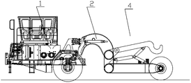
Fig. 1 is the lateral plan of hot slag slag ladle transport trolley of the present invention.
Fig. 2 is the birds-eye view of hot slag slag ladle transport trolley of the present invention.
Fig. 3 is the structural representation of lift system.
The lateral plan of the hot slag slag ladle transport trolley when Fig. 4 is put in place by lifting for hot slag slag ladle.
The specific embodiment
Below in conjunction with accompanying drawing scheme of the present invention is further specified.
As depicted in figs. 1 and 2, hot slag slag ladle transport trolley of the present invention comprises drawing head 1; Also comprise behind the U-shaped vehicle frame 3, two vehicle bridge 11 and wheels 12, vehicle frame 3 comprises crossbearer 31, two U-shaped arms 32,33 that link to each other with crossbearer 31 two ends respectively behind the U-shaped; Drawing head 1 links to each other with crossbearer 31, and two U-shaped arm 32,33 tops are all extended and are provided with a cover lift system 4; Be fixed with a vehicle bridge 11 on two U-shaped arms 32,33 respectively, wheel 12 is installed on the vehicle bridge 11.
As shown in Figure 3; Every cover lift system 4 comprises working arm 5, telescopic oil cylinder 6, first connecting rod 7, second connecting rod 8; One end of working arm 5 and crossbearer 31 are articulated in a point; The cylinder barrel end of telescopic oil cylinder 6 and crossbearer 31 hinged and b points, an end of first connecting rod 7 and the rod end of telescopic oil cylinder 6 are articulated in the e point, and the other end of first connecting rod 7 and working arm 5 are articulated in the d point; One end of second connecting rod 8 and the rod end of telescopic oil cylinder 6 are articulated in the e point, and the other end of second connecting rod 8 and a U-shaped arm 32 are articulated in the c point.Be provided with lock valve in the pilot piping of telescopic oil cylinder 6.Each U-shaped arm is provided with second connecting rod 8 is carried out the first spacing limiting stopper 9 and second limiting stopper 10.
Separate between two working arms 5; Only through the hydraulic efficiency pressure system synchronous lifting; Perhaps as shown in Figure 2, connect through tie-beam 13 between two working arms 5, the two ends of tie-beam 13 are separately fixed on two working arms 5; So that on Hydraulic Synchronizing lifting basis, realize the mechanical synchronization of two working arms 5 through tie-beam 13.
As shown in Figure 2, drawing head 1 is articulated and connected through middle articulated body 2 with crossbearer 31, and two wheels 12 are installed on each vehicle bridge 11.
Adopt hot slag slag ladle transport trolley of the present invention to carry the slag ladle operation when initial, as shown in Figure 3, second connecting rod 8 leans against on first limiting stopper 9; The connecting rod mechanism that makes telescopic oil cylinder 6, first connecting rod 7, second connecting rod 8, working arm 5 constitute keeps stable, when operating the slag ladle transport trolley near slag ladle, during transport operation; The hook-shaped prong of working arm 5 rear ends is got in the gudgeon of slag ladle both sides, control telescopic oil cylinder 6 piston rods then and stretch out, telescopic oil cylinder 6 promotes first connecting rod 7 and second connecting rod 8; Driving working arm 5 upwards rotates around a point; Slag ladle under working arm 5 hoisting force effects slowly built on stilts be lifted, when second connecting rod 8 contacts with second limiting stopper 10, this moment d, e, 3 of c draw a straight line (as shown in Figure 4); Lifting puts in place, lifts a jar action thereby accomplish.After slag ladle is raised mechanism's lifting and puts in place; Under the traction of drawing head 1, be transported to the slag field to slag ladle; Put down slag ladle by lift system work (piston rod of telescopic oil cylinder 6 shrinks, and d, e, 3 of c get back to initial position shown in Figure 3), the follow-up armful tank car that just can adopt carries out operations such as deslagging again.
Hot slag handling process of the present invention adopts special hot state slag slag ladle transport trolley, and deslagging point adopts deslagging equipment in the slag field, like driving or armful tank car deslagging.Hot slag slag ladle transport trolley of the present invention is compared and adopt to be embraced a tank car and carry, and because of its unique light and handy lift system and the lighter deadweight of car load, thereby has reduced the energy consumption and the input of handling process, has efficiently, characteristic of low energy consumption.
The present invention adopts the U-shaped rear cycle frame structure, greatly reduces dead weight of vehicle, can effectively save system power; The U-shaped rear cycle frame structure makes and utilizes little energy just can accomplish the lifting operation of slag ladle by operating mechanism's compact dimensions, and is energy-conservation, economical and practical.
After the four-bar linkage that telescopic oil cylinder of the present invention 6, first connecting rod 7, second connecting rod 8, working arm 5 constitute makes that slag ladle is lifted; Two connecting rods form straight line; Formation mechanism " dead point "; At this moment, the impact that vehicle jolts in the vehicular transport process can directly be delivered on the vehicle frame of back through connecting rod, thereby has protected telescopic oil cylinder.
More than just the present invention has been carried out exemplary explanation, concrete implementation of the present invention is not limited thereto.The insubstantial modifications that any employing design of the present invention and technical scheme are carried out is all within protection scope of the present invention.
Claims (6)
1. a hot slag slag ladle transport trolley comprises drawing head (1), it is characterized in that: also comprise vehicle frame (3) behind the U-shaped, two vehicle bridge (11) and wheel (12); Vehicle frame behind the said U-shaped (3) comprises crossbearer (31), two U-shaped arms (32 that link to each other with crossbearer (31) two ends respectively; 33), said drawing head (1) links to each other with said crossbearer (31), said two U-shaped arms (32; 33) all extend above and be provided with a cover lift system (4); Be fixed with a vehicle bridge (11) on said two U-shaped arms (32,33) respectively, wheel (12) is installed on the vehicle bridge (11).
2. hot slag slag ladle transport trolley according to claim 1; It is characterized in that: said every cover lift system (4) comprises working arm (5), telescopic oil cylinder (6), first connecting rod (7), second connecting rod (8); One end of said working arm (5) and said crossbearer (31) are hinged; The cylinder barrel end of said telescopic oil cylinder (6) and said crossbearer (31) are hinged, and the rod end of an end of said first connecting rod (7) and telescopic oil cylinder (6) is hinged, and the other end of said first connecting rod (7) and said working arm (5) are hinged; The rod end of one end of said second connecting rod (8) and telescopic oil cylinder (6) is hinged, and the other end of said second connecting rod (8) and a said U-shaped arm (32) are hinged.
3. hot slag slag ladle transport trolley according to claim 2 is characterized in that: said each U-shaped arm is provided with said second connecting rod (8) is carried out spacing first limiting stopper (9) and second limiting stopper (10).
4. hot slag slag ladle transport trolley according to claim 2 is characterized in that: also comprise a tie-beam (13), the two ends of said tie-beam (13) are separately fixed on said two working arms (5).
5. hot slag slag ladle transport trolley according to claim 1 is characterized in that: said drawing head (1) and said crossbearer (31) are articulated and connected through middle articulated body (2).
6. hot slag slag ladle transport trolley according to claim 1 is characterized in that: two wheels (12) are installed on said each vehicle bridge (11).
Priority Applications (1)
| Application Number | Priority Date | Filing Date | Title |
|---|---|---|---|
| CN 201110306085 CN102371931B (en) | 2011-10-11 | 2011-10-11 | Carrier of slag pot of hot steel-making slag |
Applications Claiming Priority (1)
| Application Number | Priority Date | Filing Date | Title |
|---|---|---|---|
| CN 201110306085 CN102371931B (en) | 2011-10-11 | 2011-10-11 | Carrier of slag pot of hot steel-making slag |
Publications (2)
| Publication Number | Publication Date |
|---|---|
| CN102371931A true CN102371931A (en) | 2012-03-14 |
| CN102371931B CN102371931B (en) | 2013-02-06 |
Family
ID=45791355
Family Applications (1)
| Application Number | Title | Priority Date | Filing Date |
|---|---|---|---|
| CN 201110306085 Active CN102371931B (en) | 2011-10-11 | 2011-10-11 | Carrier of slag pot of hot steel-making slag |
Country Status (1)
| Country | Link |
|---|---|
| CN (1) | CN102371931B (en) |
Cited By (4)
| Publication number | Priority date | Publication date | Assignee | Title |
|---|---|---|---|---|
| CN104831008A (en) * | 2015-05-29 | 2015-08-12 | 长沙凯瑞重工机械有限公司 | Rail type slag pot carrier |
| CN104831009A (en) * | 2015-05-29 | 2015-08-12 | 长沙凯瑞重工机械有限公司 | Semitrailer slag pot transporter with auto-clamping function |
| CN109132590A (en) * | 2018-10-12 | 2019-01-04 | 山东建筑大学 | A kind of dump device |
| CN113733829A (en) * | 2021-07-20 | 2021-12-03 | 山东大学 | Amphibious robot system and method for surface and interior disease detection of linear canal embankments |
Citations (3)
| Publication number | Priority date | Publication date | Assignee | Title |
|---|---|---|---|---|
| US6555049B1 (en) * | 2000-02-01 | 2003-04-29 | Kress Corporation | Steel manufacturing facility and method |
| CN101435267A (en) * | 2008-12-19 | 2009-05-20 | 三一重工股份有限公司 | Arm support link mechanism, folding type arm support and concrete pump vehicle |
| CN202272089U (en) * | 2011-10-11 | 2012-06-13 | 中冶宝钢技术服务有限公司 | Carrying cart for thermal-state slag tank |
-
2011
- 2011-10-11 CN CN 201110306085 patent/CN102371931B/en active Active
Patent Citations (3)
| Publication number | Priority date | Publication date | Assignee | Title |
|---|---|---|---|---|
| US6555049B1 (en) * | 2000-02-01 | 2003-04-29 | Kress Corporation | Steel manufacturing facility and method |
| CN101435267A (en) * | 2008-12-19 | 2009-05-20 | 三一重工股份有限公司 | Arm support link mechanism, folding type arm support and concrete pump vehicle |
| CN202272089U (en) * | 2011-10-11 | 2012-06-13 | 中冶宝钢技术服务有限公司 | Carrying cart for thermal-state slag tank |
Cited By (6)
| Publication number | Priority date | Publication date | Assignee | Title |
|---|---|---|---|---|
| CN104831008A (en) * | 2015-05-29 | 2015-08-12 | 长沙凯瑞重工机械有限公司 | Rail type slag pot carrier |
| CN104831009A (en) * | 2015-05-29 | 2015-08-12 | 长沙凯瑞重工机械有限公司 | Semitrailer slag pot transporter with auto-clamping function |
| CN109132590A (en) * | 2018-10-12 | 2019-01-04 | 山东建筑大学 | A kind of dump device |
| CN109132590B (en) * | 2018-10-12 | 2020-06-02 | 山东建筑大学 | Dumping device |
| CN113733829A (en) * | 2021-07-20 | 2021-12-03 | 山东大学 | Amphibious robot system and method for surface and interior disease detection of linear canal embankments |
| CN113733829B (en) * | 2021-07-20 | 2023-09-22 | 山东大学 | Amphibious robot system and method for surface and internal disease detection of linear canal embankments |
Also Published As
| Publication number | Publication date |
|---|---|
| CN102371931B (en) | 2013-02-06 |
Similar Documents
| Publication | Publication Date | Title |
|---|---|---|
| CN206108800U (en) | Special moving staircase of aircraft maintenance personnel | |
| CN102371931B (en) | Carrier of slag pot of hot steel-making slag | |
| CN103866060A (en) | Hinged connection type U-shaped slag tank vehicle | |
| CN103060499B (en) | Hinged U-shaped slag pot carrier | |
| CN203359580U (en) | Lifting-type traction loading and unloading platform | |
| CN202625655U (en) | Tower tube transporter | |
| CN204569328U (en) | Gravity type boat davit steel pipe bracket car and steel pipe clamping mechanism thereof | |
| CN203112854U (en) | Hinged U-shaped slag pot carrier | |
| CN202671139U (en) | Hydraulic transport vehicle | |
| CN201301175Y (en) | Deformation type transporter | |
| CN102745623A (en) | Hydraulic carrier | |
| CN104709851A (en) | Gravity type steel tube clamp forklift and steel tube clamping mechanism and steel tube clamping and forking method thereof | |
| CN201650114U (en) | Wheel rotary drilling machine | |
| CN204124021U (en) | A kind of cylindrical shell transport trolley | |
| CN201296611Y (en) | Electric hydraulic crane | |
| CN218085175U (en) | Flexible mobile contact net for large freight yard containers | |
| CN103498418A (en) | Device for shifting hanging basket assembly pieces and construction method | |
| CN102700450A (en) | Self-propelled hydraulic plate for conveying tower drum | |
| CN202272089U (en) | Carrying cart for thermal-state slag tank | |
| CN202465199U (en) | Reach truck mast | |
| CN205553846U (en) | A air suspension system that is used for 2nd steering axle gasbag of commercial car to promote | |
| CN201027157Y (en) | Operating vehicle for railway electrification contact screen | |
| CN202671136U (en) | Lifting transportation forklift | |
| CN205273601U (en) | Frame goes up and down to turn to device before hot metal bottle carrier | |
| CN209940322U (en) | Crawler-type stack type support transfer cart |
Legal Events
| Date | Code | Title | Description |
|---|---|---|---|
| C06 | Publication | ||
| PB01 | Publication | ||
| C10 | Entry into substantive examination | ||
| SE01 | Entry into force of request for substantive examination | ||
| C14 | Grant of patent or utility model | ||
| GR01 | Patent grant |