CN102341655B - Direct forced draft fluid cooler/cooling tower and liquid collector therefor - Google Patents
Direct forced draft fluid cooler/cooling tower and liquid collector therefor Download PDFInfo
- Publication number
- CN102341655B CN102341655B CN201080010125.2A CN201080010125A CN102341655B CN 102341655 B CN102341655 B CN 102341655B CN 201080010125 A CN201080010125 A CN 201080010125A CN 102341655 B CN102341655 B CN 102341655B
- Authority
- CN
- China
- Prior art keywords
- tank
- liquid
- supporting plate
- plate structure
- forced ventilation
- Prior art date
- Legal status (The legal status is an assumption and is not a legal conclusion. Google has not performed a legal analysis and makes no representation as to the accuracy of the status listed.)
- Expired - Fee Related
Links
Images


Classifications
-
- F—MECHANICAL ENGINEERING; LIGHTING; HEATING; WEAPONS; BLASTING
- F28—HEAT EXCHANGE IN GENERAL
- F28C—HEAT-EXCHANGE APPARATUS, NOT PROVIDED FOR IN ANOTHER SUBCLASS, IN WHICH THE HEAT-EXCHANGE MEDIA COME INTO DIRECT CONTACT WITHOUT CHEMICAL INTERACTION
- F28C1/00—Direct-contact trickle coolers, e.g. cooling towers
- F28C1/02—Direct-contact trickle coolers, e.g. cooling towers with counter-current only
-
- F—MECHANICAL ENGINEERING; LIGHTING; HEATING; WEAPONS; BLASTING
- F28—HEAT EXCHANGE IN GENERAL
- F28F—DETAILS OF HEAT-EXCHANGE AND HEAT-TRANSFER APPARATUS, OF GENERAL APPLICATION
- F28F25/00—Component parts of trickle coolers
- F28F25/02—Component parts of trickle coolers for distributing, circulating, and accumulating liquid
- F28F25/04—Distributing or accumulator troughs
-
- F—MECHANICAL ENGINEERING; LIGHTING; HEATING; WEAPONS; BLASTING
- F24—HEATING; RANGES; VENTILATING
- F24F—AIR-CONDITIONING; AIR-HUMIDIFICATION; VENTILATION; USE OF AIR CURRENTS FOR SCREENING
- F24F3/00—Air-conditioning systems in which conditioned primary air is supplied from one or more central stations to distributing units in the rooms or spaces where it may receive secondary treatment; Apparatus specially designed for such systems
- F24F3/12—Air-conditioning systems in which conditioned primary air is supplied from one or more central stations to distributing units in the rooms or spaces where it may receive secondary treatment; Apparatus specially designed for such systems characterised by the treatment of the air otherwise than by heating and cooling
-
- F—MECHANICAL ENGINEERING; LIGHTING; HEATING; WEAPONS; BLASTING
- F28—HEAT EXCHANGE IN GENERAL
- F28C—HEAT-EXCHANGE APPARATUS, NOT PROVIDED FOR IN ANOTHER SUBCLASS, IN WHICH THE HEAT-EXCHANGE MEDIA COME INTO DIRECT CONTACT WITHOUT CHEMICAL INTERACTION
- F28C1/00—Direct-contact trickle coolers, e.g. cooling towers
-
- F—MECHANICAL ENGINEERING; LIGHTING; HEATING; WEAPONS; BLASTING
- F28—HEAT EXCHANGE IN GENERAL
- F28D—HEAT-EXCHANGE APPARATUS, NOT PROVIDED FOR IN ANOTHER SUBCLASS, IN WHICH THE HEAT-EXCHANGE MEDIA DO NOT COME INTO DIRECT CONTACT
- F28D5/00—Heat-exchange apparatus having stationary conduit assemblies for one heat-exchange medium only, the media being in contact with different sides of the conduit wall, using the cooling effect of natural or forced evaporation
- F28D5/02—Heat-exchange apparatus having stationary conduit assemblies for one heat-exchange medium only, the media being in contact with different sides of the conduit wall, using the cooling effect of natural or forced evaporation in which the evaporating medium flows in a continuous film or trickles freely over the conduits
-
- F—MECHANICAL ENGINEERING; LIGHTING; HEATING; WEAPONS; BLASTING
- F28—HEAT EXCHANGE IN GENERAL
- F28F—DETAILS OF HEAT-EXCHANGE AND HEAT-TRANSFER APPARATUS, OF GENERAL APPLICATION
- F28F25/00—Component parts of trickle coolers
- F28F25/02—Component parts of trickle coolers for distributing, circulating, and accumulating liquid
-
- Y—GENERAL TAGGING OF NEW TECHNOLOGICAL DEVELOPMENTS; GENERAL TAGGING OF CROSS-SECTIONAL TECHNOLOGIES SPANNING OVER SEVERAL SECTIONS OF THE IPC; TECHNICAL SUBJECTS COVERED BY FORMER USPC CROSS-REFERENCE ART COLLECTIONS [XRACs] AND DIGESTS
- Y10—TECHNICAL SUBJECTS COVERED BY FORMER USPC
- Y10T—TECHNICAL SUBJECTS COVERED BY FORMER US CLASSIFICATION
- Y10T137/00—Fluid handling
- Y10T137/8593—Systems
Landscapes
- Engineering & Computer Science (AREA)
- Mechanical Engineering (AREA)
- General Engineering & Computer Science (AREA)
- Physics & Mathematics (AREA)
- Thermal Sciences (AREA)
- Chemical & Material Sciences (AREA)
- Combustion & Propulsion (AREA)
- Heat-Exchange Devices With Radiators And Conduit Assemblies (AREA)
Abstract
Direct forced draft fluid cooler/closed loop cooling towers and cooling towers are provided with fans at the bottom of the unit, and a plurality of layers of water collection troughs or channels above the fans to capture water droplets sprayed downwardly from the top of the device through a heat exchanger or fill media above the collection troughs. In one embodiment the collection troughs supply the collected water to one or more gutters inside the housing which lead the water to an external collection tank from which the water is recirculated through the system.
Description
The U.S. Provisional Patent Application No.61/208 of application on March 3rd, 2009 is enjoyed in this application request, 995, the No.61/217 of application on June 5th, 2009, the No.61/270 of application on July 13rd, 822 and 2009,723 right, the disclosure at this with reference to these documents is attached in the application.
Technical field
The present invention relates generally to the cooling tower of direct forced ventilation fluid cooler/closed loop cooling tower and/or compact conformation, relate in particular to a kind of drainage collection system that improves oxygen diffusion for this cooler and cooling tower.
Background technology
Traditional industrial cooling tower comprises so-called counterflow cooling tower, the water in cooling tower or other liquid is fallen or by Jet with downward flow direction, form in the opposite direction adverse current with the air moving up in cooling tower.This type systematic may be used on various occasions, comprises water/air washer, dust collection equipment, air cooling compressor, evaporative type cooler, fluid cooler or closed loop cooling tower, evaporative condenser or similar devices.Conventionally these industrial cooling towers are quite large and be permanent plant, comprise that very large bottom water leg collects the water flowing down.
Built that some relatively small-sized cooling towers come for this classification, they easily transport, and can be applicable to various occasions, for example small-sized roof cooling tower.For example, authorize U.S. Patent No. 5,227,095 and the No.5 to Harold D.Curtis, 487, No. 531 single module cooling tower is disclosed, the easily transportation of its size, the preprocessing of Ke factory, thereby easily install at the scene, can meet on-the-spot special water/liquid refrigeration or process the required performance of engineering.The disclosed system of patent of Curtis has one or more blower fans that deliver air to cooling tower, is positioned at cooling tower bottom, under filler, evaporation refrigeration medium or liquid cools coil pipe.Blower fan forced air upwards flows straight in cooling tower.These systems are usually directed to direct forced ventilation counter-flow cooling tower.
Patent No.5, discloses the modular system of another direct forced ventilation counter-flow cooling tower for 545, No. 356, and its bottom has blower fan.
These systems all use large header tank or catch box, groove or pond to collect the also recirculated water of containment.These casees or groove are conventionally very large, because they must hold abundant liquid, come, for giving system, also to comprise all connecting pipes.(the water normally because treatment fluid of these systems, but water always not) by purify air and build-up of air in particle, these particles will be deposited in case, groove or pond, thereby needing these casees of periodic cleaning, groove or pond, the large quantity of fluid in system must be poured out, clean or be processed so.These casees, groove and pond become inner sediment box in essence.This class case needs often to safeguard, and requires workman to enter in the confined space to clean.Meanwhile, large quantity of fluid itself also needs to carry out water treatment or chemical treatment and can not directly dispose, thereby has further increased cost.In addition, the amount of liquid in this type systematic has increased system weight greatly, thereby has increased roof load.
Except deposition, amount of liquid and removing problem, previously mentioned cooling tower systems can not solve the oxygen diffusion problem of their corresponding liquor collecting systems completely.Conventionally, the abundant degree that the efficiency of cooling tower (or be similar to other cooling tower structures of the fluid cooler) is mixed with defluent liquid by the air upwards flowing decides.Certainly, the blower fan in this type systematic is circular, because blower fan can not transmit balanced air-flow, thereby air can not be distributed equably through tower medium or element.Thereby, for example, in U.S. Patent No. 5,227,095 and No.5, in 487,531 disclosed systems, in liquid trap, used a plurality of parallel longer collecting boaries, their tilt and are stacked.Even if air is not blocked, these plates also can limit air and flow on the territory, wainscot wall area of tower, cause that air flows on the packing medium or heat exchanging fluid cooling coil of top, thereby force large quantity of air to flow at a certain angle a side of tower or housing.Really, these collecting boaries are supported in tower shell by horizontal support piece or plate conventionally, and these support members or plate can stop or limit air through them, thereby have stoped the horizontal proliferation of air between them.These factors have affected air quality and the diffusion entering in tower greatly, thereby have reduced the thermal performance of tower.
Goal of the invention
The cooling tower and/or the fluid cooling system that the object of this invention is to provide a kind of improved, easy transportation.
Another object of the present invention is to provide a kind of improved air diffuser and liquor collecting system, for forced draught cooling tower and fluid cooler, can strengthen the property, reduce maintenance cost.
Another object of the present invention has been to provide cooling tower and/or the fluid cooler of a kind of low profile, easily transportation, its liquor collecting system can reduce system liquid load, be convenient to clean and/or replacement fluid.
Summary of the invention
According to an aspect of the present invention, cooling tower and/or fluid cooler/closed loop cooling tower of a kind of low profile, easily transportation are disclosed, it comprises novel liquid collecting/catchment/air diffuser system, and this system is positioned on the one or more blower fans on tower shell pedestal.Liquid trap of the present invention is positioned under the packing medium of tower or under the heat exchange coil of fluid cooler.Liquid trap is collected substantially and is flow through all liq of filler or heat exchange coil, then these liquid is imported in one or more inner rhone, rhone is transported to collected liquid in collected outside case, and then the liquid in collecting box turn back to top of tower.Liquid trap is also constructed such that the oxygen diffusion of discharging from blower fan is to the width range of tower, the supporting construction of passing liquid trap, thereby is uniform through the air-flow of packing medium or heat exchange coil.
According to a further aspect in the invention, the cooling tower of low profile, easily transportation and/or fluid cooler have outside catchment/catch box, the liquid that it holds relatively small amount, is positioned at blower fan apparatus sidepiece, easily enters wherein and cleans.
According to a further aspect in the invention, provide a kind of use at low profile, the cooling tower of easily transportation and/or catchment/liquid collecting and the air-diffuser in liquid chiller, by a plurality of tanks that grow, that cross section is V-arrangement or U-shaped, formed, these tanks are separated from each other in side direction, thereby form or defined multilevel access.Tank skew in tank on every layer and its upper strata or lower floor, can substantially catch all liq of past current downflow in tower, thereby between packing medium or heat exchanger and blower fan, formed 100% completely dry/wet type baffle plate, and the mobile air-flow that makes to make progress evenly spread.
Of the present invention catchmenting/liquor collecting system can be used in some equipment, as water/air washer, dust catcher, cooling tower, evaporative type cooler, fluid cooler, evaporative condenser with make water or other fluid liquids wash, any equipment of clean or sweat cooling.Although describe together with the cooling tower of this system and low profile, easily transportation and/or fluid cooler, use, this liquid collecting/air diffuser system can be used together with having any system in tradition bottom dislodger and pond.
Except collecting defluent all liq, this liquor collecting system also provides a kind of low pressure member, can make air between collecting tank, flow straight up, then arrive cooling medium or fluid cooling coil system.To forming the passage of tank, carried out ingenious location, bootable and diffusion is to the air at upper reaches, thereby makes air-flow pass through more equably packing medium or heat exchanger.The structure of liquid trap can make air be horizontally through support system, thus even diffused air.Thereby more effectively mixed gas-liquid, greatly improved the thermal performance of heat exchanger or cooling tower.In addition, in previously mentioned liquid trap, the pressure drop across collecting board is very large.Compared with the prior art, the present invention will reduce this pressure drop.This will further improve the thermal performance of heat exchanger or cooling tower.And, compare with current technology, can produce liquor collecting system of the present invention more economically.The water no matter being collected is finally imported into or where is contained in, and all has these advantages.
Due to structure of the present invention, can not need the bottom of tower blower fan around or under use case, groove or pond, thereby reduced height and the weight of tower.Also reduced the manufacturing cost of equipment.In addition, the traditional structure under being positioned at blower fan with catch box is compared, and at blower fan sidepiece, uses outside catch box to reduce the amount of the required treatment fluid of system.According to the present invention, only need enough liquid to feed system and there is enough pump heads and prevent water pump cavitation.
Liquid collecting/air diffuser system of the present invention with forced ventilation air system comprise the blower fan that is arranged on tower bottom, use such system to there are some advantages.
The first, blower fan operates under wet type air system outside and tower structure, thereby prevents that blower fan is subject to the destruction of natural cause.This specific character has reduced the maintenance cost of blower fan greatly, has extended the service life of blower fan.In addition, because blower fan is easy to approach, thereby do not need the wet area of not environmental protection in maintenance personal's access arrangement just can overhaul blower fan and/or blower fan is removed from equipment below.This specific character will reduce maintenance cost greatly, can not allow maintenance personal suffer any unnecessary health risk.
The second, owing to being easy to use the blower fan of bottom installation, just do not need air-breathing skylight and forced ventilation chamber, this is because liquor collecting system has spread the mobile air that makes progress.In addition, owing to not needing to configure forced ventilation chamber and air-breathing skylight, thereby will reduce device height.Air can be drawn into the space between roof or floor and blower fan from equipment below like this.The minimizing of device height and weight will further reduce to safeguard, transports and promote cost.
The 3rd, the blower fan that is arranged on bottom is higher than the fan efficiency that is arranged on top or sidepiece.In the time of in air-flow moves to the square box of circular blower fan, determine that it is challenging that air-flow is distributed on cooling medium sufficiently uniformly.Be transported to air in tower (thering is the blower fan that is arranged on top or sidepiece) before entering cooling medium, must from horizontal direction, turn to vertical direction to flow rapidly, thereby air just can be evenly through medium bottom.Thereby can produce idle space.Because assembling is in bottom, air can be inhaled in the open space between ground or roof and blower fan, and when air passes blower fan, air can rotate 90 degree.Air can laterally inwardly flow under tower, then towards filler center, moves.In legacy system, this air-flow is easy on cooling tower border form idle space around.This part changes over to move upward from transverse movement and causes because air is difficult to rotate 90 degree.In addition, the blower fan of forced draught cooling tower is near tower center, thereby all air-flows are easily concentrated into funnel-form towards packing medium center.Due to structure of the present invention, blower fan, towards the filler of liquid trap and liquid trap top or the very powerful air-flow of downside generation of heat exchange coil, has effectively carried out high pressure forced ventilation, thereby has relatively spread equably the mobile air that makes progress.Thereby the blower fan that is arranged on bottom has carried out gas-liquid mixed more efficiently, has significantly improved thermal performance.
In addition, warm air vertically rises conventionally.Can optimize this natural energy and increase air-flow efficiency.
Liquor collecting system of the present invention can be designed to hold all liq that flows down from tower, then these liquid are imported in the rhone one or two sidewall of towers or housing.One end of these rhones is closed, thereby liquid is flowed in the outside catch box on equipment one end in one direction.Outside catch box of the present invention is also useful, because it does not need, as all water refrigeration plants, water tank or pond are arranged in to equipment below completely.Because these water tanks are collected toward dirty water or liquid, the air plankton of staying in liquid is assembled and is deposited in case.Thereby the necessary cleaned at regular intervals of these casees, thereby need high maintenance cost.These casees must include the liquid of certain vertically degree of depth to guarantee sufficient pump head, so just there will not be the cavitation phenomenon of pump.
Four sides of outside catch box bottom are inclination or taper, thereby form limited little space in positive bottom.The impurity of mud, dirt and other moisture or liquid, by depositing in the little space segment of tilting bottom of case, can reduce costs like this aspect several.
First, because there is no case, the cost of cleaning case has just saved completely so.Thereby regularly with valve, dirt is disposed from the bottom of catch box manually or automatically.Can remove these dirts by drainpipe or other members of standard.If also need to clean catch box, open case lid and just can easily enter in catch box.Due to cleaning case automatically, remove deposit, just do not need the confined space of access arrangement to clean, thereby just can not suffer any unnecessary health hazard or remove relevant environmental risk to deposit.
The second, outside catch box only needs minimum liquid to carry out feed system.Compare with conventional boxes, this feature can reduce weight of equipment greatly.As mentioned above, this liquid must regularly be processed; Utilization, according to catch box of the present invention, only need the liquid of a small amount of gallon to purify this system, and traditional catch box needs into hundred gallons of fluid.
The 3rd advantage is: compare with ground catch box, and the liquor collecting system of the application of the invention, pump needs less pump head that liquid is turned back in liquid mixing system.The required effective pump head of pump equals upper liquid level in case and the difference in height between liquid distribution pipe.On the other hand, the pump head of legacy system must be from the residing ground of catch box until the residing tower of liquid mixing system the top.And the required pump head of pump is only several feet in the present invention, thereby greatly reduced required pumpability.Compare with traditional forced ventilation tower, the operator of tower of the present invention can cost saving.
From above-mentioned discussion, can find out: compare with being widely used in industrial induced draught counter-flow water cooling tower, direct forced ventilation contracurrent system of the present invention has many advantages.
First, major advantage is: owing to not needing water tank, skylight and having reduced the total height of structure, thereby reduced the initial stage construction cost of modular construction.Modular construction of the present invention can preprocessing, and the induced draught counter-flow cooling tower of built on-site can not carry out preprocessing conventionally.
The second, because the space of blower fan below is opened wide, can enter from below this space, thereby can very easily contact blower fan.
The 3rd, Fan Equipment of the present invention is carried out intense impact to the air of upwards flow in water collector, then enter packing medium or heat exchange coil, thereby can more even diffused air, when air is strong, clashes into while flowing into the water in tower downwards more preferably cooling-air.Form therewith sharp contrast, the air-flow of induced draught cooling tower is quite thin.
Another advantage is: when blower fan uses forced ventilation mode rather than induced draught pattern, conventionally can greatly improve fan efficiency.In addition, the very close packing medium of blower fan or heat exchange coil can reduce the operating fluid pressure loss, have again improved fan efficiency.
In a word, when collecting system is used in water operating equipment, can be cost-saving, avoided the healthy and safe risk relevant with wetting system, also have following advantages, comprising:
Improved thermal performance,
Reduced energy resource consumption,
Reduced water capacity and the water weight in equipment,
Reduced water and chemicals requirement,
Reduce maintenance cost, increased equipment life,
Reduced weight of equipment,
Do not need to use air-breathing skylight,
Do not need to use forced ventilation chamber
Reduced the structure height of equipment,
Do not need to use water tank,
Reduced manufacturing cost,
Can from moist discharge air-flow, remove Fan Equipment,
Tank can carry out automatically cleaning,
Avoided the cavitation of pump,
Environmental protection,
Do not need to enter wet environment and safeguard water tank or blower fan.
Read in conjunction with the drawings the detailed description to illustrated embodiment below, for the person of ordinary skill of the art, above and other object of the present invention, characteristic and advantage are apparent.
Accompanying drawing explanation
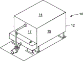
Fig. 1 is the perspective view of direct forced ventilation/fluid cooler constructed according to the invention;
Fig. 2 is that the cooler of the present invention shown in Fig. 1 is removed sidewall side view afterwards;
Fig. 3 is along the profile shown in the line 3-3 in Fig. 2;
Fig. 4 is the profile that is similar to Fig. 3, shows another embodiment of the present invention, in this embodiment, is provided with evaporative cooling tower;
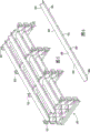
Fig. 5 is according to the perspective view of a part for water collector of the present invention;
Fig. 6 is the enlarged perspective that uses a tank in water collector shown in Fig. 5;
Fig. 7 is the perspective view that is similar to Fig. 5, shows a pair of water collector part of using the tank in Fig. 6 and linking together;
Fig. 8 is the amplification view of the gripper shoe in the water collector part of using in Fig. 5;
Fig. 9 is the side view along the gripper shoe shown in the line 9-9 of Fig. 8;
Figure 10 is the side view of the second embodiment of gripper shoe, shows two adaptive plates that connect;
Figure 11 is the schematic side elevation of a part for water collector system, shows correlation between tank and the correlation between the air flow path between tank;
Figure 12 is the fragmentary, perspective view that is similar to Fig. 5, shows water collector system according to another embodiment of the present invention;
Figure 13 is the schematic side elevation that is similar to Figure 11, shows correlation between the tank in embodiment illustrated in fig. 12 and the correlation between the air flow path between tank;
Figure 14 is the side view that is similar to Figure 11, shows and uses baffle plate to flow out from water collector with anti-sealing when blower fan is not worked;
Figure 15 is the side view that is similar to Figure 14, shows the part of baffle plate when blower fan is worked;
Figure 16 a and 16b are the schematic side elevations of a pair of water collector unit, and one deck tank in water collector unit has the baffle plate can pivotable being connected thereto;
Figure 17 is the elevation view of header tank used according to the invention;
Figure 18 is the side view of the header tank of Figure 17;
Figure 19 is the top view of the header tank of Figure 17;
Figure 20 is the side view for another embodiment of gripper shoe of the present invention;
Figure 21 is the side view of the tank that uses together with the connecting plate with Figure 20;
Figure 22 is the local enlarged perspective of collecting system, and this collecting system has been used connecting plate and the tank in Figure 21 (only having shown in the accompanying drawings a tank) of Figure 20.
The specific embodiment
, in detail with reference to accompanying drawing, first with reference to Fig. 1, show direct forced ventilation fluid cooler 10 now.This cooler is designed to utilize easily the evaporation of water or other fluids to carry out the second fluid in the heat exchanger in cooling device.System of the present invention can be used together with water or other suitable liquid, although make water in the embodiment that the present invention explains, the present invention is not limited to and makes water.
Water collector 30 is also in housing 12 and be positioned under heat exchanger 24, from water distribution system 20 out, then the water through the space between coil system is collected in water collector 30.One or more blower fan 32 is arranged on housing 12 bottoms, it is supported on this bottom with any traditional approach, blower fan 32 is by the bottom opening suction gas of housing, then gas is blown on water collector 30 and cooling coil 24, air-flow just forms adverse current with the water distributing from water distribution system 20 like this.
Water distribution system 20 comprises the header tank 34 that is arranged on housing 10 outsides, is roughly positioned in same level with blower fan, and header tank 34 holds the collected water of gathering system 30, and which will be described below.The water being collected is discharged to pump 38 from header tank 34 by drainpipe 36.Pump recycles these liquid by sparge pipe 40, and in housing, a plurality of nozzles 42 are connected on sparge pipe 40.In housing, these nozzles form downward injection water above heat exchange coil 24.These nozzles can be any known structures, are suitable for using in fluid cooler or cooling evaporative cooler, but No. WO2009/070691 disclosed nozzle arrangements of PCT International Publication preferably.
A kind of dehydrater structure 44 of known configurations form is arranged in the open top 14 of housing 12, can block, catches and collect the water smoke blowing out from heat exchange coil 24, thereby has prevented that water smoke from entering in atmosphere.This dehydrater is known in the art, thereby does not need to describe in detail at this.U.S. Patent No. 5,227,095 and No.5, example and the installation thereof of suitable dehydrater are disclosed in 487, No. 531.Can carry out combination with reference to disclosure and the present invention of these two pieces of patent documentations.
As shown in Figures 2 and 3, housing 12 and installation equipment are within it supported on floor or ground by the base support of support member, I shape truss 46 or any other suitable structure, or, be for example supported on building roof.Thereby, between the bottom 16 of housing 12 and floor support, be formed with space, to allow air to flow in the formed space 49 of this structure, then the air in space 49 is drawn in housing by blower fan 32.
Fig. 3 in accompanying drawing is along the sectional view shown in the line 3-3 of Fig. 2, has taken off housing rear wall 17 to show its internal structure in this figure.As shown in the figure, heat exchange coil 24 comprises that one group of pipeline rolls up to form coil pipe, thereby the flow path of fluid to be cooled, that enter coil pipe entrance 26 in cooler is relatively longer, counter-flow air and liquid that distribute from water distribution system 20, that pass this path will cooling described fluids like this.Can manufacture coil arrangement by any suitable method, can adopt any suitable method commonly known in the art by support or housing with holes 46, coil arrangement to be supported in housing 12.
As shown in Figures 2 and 3, collecting system 30 comprises one group of V-arrangement tank 50, and these tanks are arranged to multilayer, will be described in more detail this multilayer arrangement below.These tanks are collected the liquid through coil pipe 24, thereby block, then guide them away from blower fan 32 these liquid.As shown in Figure 3, the end of tank 50 is openings, and collecting system 30 is supported on the L shaped wall construction 52 of housing 12 every sides.This wall construction stretches along the length direction of housing, and housing sidewall forms rhone.The 54,Gai aperture, aperture that two rhones are sent to water near header tank 34 is connected with the corresponding aperture on header tank by waterproof seal or similarity piece, thereby the water being collected flows in header tank, then recycles as described above.
, referring again to the Fig. 5 in accompanying drawing, show the local enlarged perspective of collecting system 30 now.Fig. 6 shows separately a tank 50.As shown in Figure 5, whole catchmenting/liquid system 30 consists of a plurality of unit or parts 60 of catchmenting, and these unit 60 that catchment link together as shown in Figure 7, and which will be described below.Each unit 60 comprises a plurality of tank gripper shoes or supporting construction 62, has the aperture 64 that is installed in tank 50 in gripper shoe or supporting construction 62.These gripper shoes are made by molded plastics or the similar material of light weight.In illustrated embodiment, be provided with four gripper shoes, but the quantity of gripper shoe is determined according to the size of the unit that catchments.In the embodiment of the present invention shown in Fig. 5 and 6, tank 50 is V-arrangement normally, by flexible metal or plastics, is made, and the component 66 of tank is just flexible like this, thereby be convenient to tank, is bonded in gripper shoe.
Fig. 8 illustrates in greater detail gripper shoe 62, and the aperture in gripper shoe 64 has the bottom periphery structure that is substantially V-arrangement as can be seen from Figure, complementary with the v-shaped structure of tank 50.The V-arrangement edge 64a in aperture 64 ends at abutting part 64b place, and abutting part 64b has formed otch 64c onboard in the end of edge 64a.The top 64d in aperture 64 is somewhat arc.This structure can make the flexible V-arrangement tank of V-arrangement slight curvature, and tank component 66 just can be slightly mutually close like this, thereby tank just can longitudinally insert in aperture 64.In the time of in the aperture of tank appropriate location at perforated plate, the notch 68 being formed on tank component 66 will snap in the position under the otch 64c on plate.This structural configuration makes collecting system arrangement of components have the member of mutual adaptation, thereby can tank is fixed in gripper shoe and make gripper shoe stable.
Notch in this system and notch features can not need to use machanical fastener just can assemble, and can keep modular construction complete simultaneously.Also quick detachable.
Except easy assembling, this structure of gripper shoe can form the gas channel through plate above tank, like this, even if be full of liquid in tank, air also can pass between gripper shoe, thereby can guarantee that air is to side direction uniformly dispersing when air process water collector.
With reference to Fig. 8 and 9, on the end 70 of gripper shoe 62, be formed with transverse wall portion element 72.As shown in Figure 7, when one group of catchment element 60 is positioned in housing, these wall portion elements will adjoin each other.In addition, as shown in Fig. 5,7 and 8, on the end 70 of gripper shoe, be formed with part aperture 64, the corresponding part aperture in they and adjacent panel is complementary, thereby when the end abutment of plate, these part apertures just can form a complete aperture.By this structural configuration, when V-arrangement tank 50 snaps in aperture, tank, from forming and connect between two gripper shoes, links together catchment element 60.Although illustrating on each edge of gripper shoe 62, illustrated embodiment there are two this part apertures,, the quantity in this part aperture is determined according to the size of plate.
As shown in Figure 9, the bottom margin 74 of gripper shoe 62 has the thin scarcement 75 extending from this bottom margin, thereby supporting surface 78 is provided on bottom margin 74, and supporting surface 78 is supported in the top of the draining cell wall 52a of portion (Fig. 3).In addition, if use the unit that catchments more than one deck, these unit that catchment can be mutually stacked, and supporting surface 78 is placed on the top edge 79 of gripper shoe 62.
Although the preferred embodiments of the present invention provide liquid collecting passage with above-mentioned V-arrangement tank 50, thereby by the guiding fluid rhone of collecting, be construed as: also can use the tank of other suitable shapes, as U-shaped tank.In addition, although showing the opposite end of tank, opens Fig. 3, water is transported in a pair of rhone; But if needed, one end of tank can be closed, all liq can only be transported in a rhone on housing like this.
Referring now to Figure 11, the tank schematically showing on water collector is arranged.From figure, can find out, the air flowing out from blower fan, through lower floor's tank 50, through the space between tank, is diffused facing to the bottom of gullet above it.In addition, because aperture 64 is formed on plate 62, the top, aperture that is positioned at tank top is large, thereby even if be full of water (as shown by arrow B) in tank as schematically shown in Figure 11 upper right side, air also can arrive through plate 62 opposite side of plate.At multilayer tank relaying, continue and carry out this diffusion way, like this in the complete cross direction profiles of collecting system top air, air-flow passes cooling coil equably, thereby can carry out equably heat exchange.As shown in figure 11, the tank 50 in every layer is spaced laterally apart mutually, and departs from respect to the tank in its upper strata or lower floor.When water smoke or water droplet process water collector, liquid will flow downward towards blower fan; Because the distance 78 between every layer of tank end is less than tank width, thereby will increase the chance that tank is collected these liquid.
In a preferred embodiment, the width between the component of single tank is roughly 3 inches (inch), and spacing between the end of contiguous branch part is 2 inches (inch).
Have been found that: by using five layers of tank (as shown in Fig. 2-9), process heat exchanger, these water droplets that turn back in header tank 34 roughly can be collected on 100% ground.But, if desired, can use more than five layers or be less than the tank of five layers.
Certainly be construed as: spacing between above-mentioned tank is identical is not necessary.Really, according to application or the concrete shape of housing, make spacing difference between tank that air-flow is imported to specific region and also will fall within the scope of protection of the present invention.In addition, make the port size difference of adjacent tank will affect the air velocity between this adjacent tank.By making the spacing between tank different, can make air more balancedly be diffused in system.But, importantly need to make as described above tank to keep stacked, water just can not flow in blower fan like this.
Figure 10 shows and the similar supporting plate structure of aforementioned structure, but has used four layers to collect tank.In this case, the end construction of gripper shoe 62 ' is slightly put difference, and the edge of gripper shoe is interlaced, and the transverse wall 72 in end edge is overlapping, thereby can mutually support.On these transverse walls, can be formed with clamping adapter structure, as the U-shaped structure of depression, can hold and smooth, the relative edge 72 ' of engage adjacent plate operationally, thereby adjacent panel is fastened togather.
Figure 12 and 13 schematically shows another embodiment of the present invention.In this case, as previous embodiment, do not use each single tank 50, but be provided with tank to 80, tank connects by all-in-one-piece disc 82 80, and disc 82 vertically stretches between the right summit of tank.These structures can snap in the aperture in gripper shoe, and these apertures are corresponding with aforementioned aperture 64.But the gripper shoe in this embodiment comprises slit 83, slit 83 stretches to hold disc 82 between aperture 64.Figure 12 only schematically shows plate and aperture thereof.By the paired tank connecting by means of web 82 is provided, to a certain extent for this structure provides larger rigidity, but can keep the oxygen diffusion through gripper shoe.
Referring again to Fig. 8, tank gripper shoe comprises formation rib 90 thereon, and away from tank, the tank towards its below stretches downwards rib 90.Have been found that: in the process of the operating cooler according to the present invention, the liquid flowing out from system 20 can condensation on the surface of gripper shoe, then with thin layer form, along gripper shoe, flows downward.Need to collect this condensate not allow them enter blower fan region.Thereby when condensate layer moves down, rib 90 breaks condensate layer, and guided in the below water leg being close to.Similarly, condensate also can be formed on the inner surface of cooling tower wall portion.Thereby, as shown in Figure 2, on end wall 17, be arranged on deflecting plate 96, to allow condensate flow in tank along wall portion downwards.As shown in Figure 3, on sidewall, do not need this deflecting plate 96 is set, because bootable condensate directly flows in rhone downwards.
Referring now to Fig. 4, technology of the present invention is suitable for using in devaporizer equally.In devaporizer, replace through coil pipe 24, liquid is inversely through the evaporative cooling medium in known configurations (these cooling mediums form layer 100 in housing 12).Evaporative cooling medium can adopt various structures form, and the lateral wave card that normally plastics are made can form gas channel between them, and liquids and gases are oppositely through this passage.When contact with moisture air, moisture evaporates in medium, thus the cooling air for air-conditioning system or similar system.
As mentioned above, although illustrating and describe this collecting system combines with fluid cooler compact, easily transportation or cooling tower (this cooling tower has the blower fan system that is positioned at bottom), but this water collecting structure can be used in more traditional system, this traditional system has traditional collecting-tank or the water leg being positioned under liquid chiller or packing medium; For example this water collecting structure can with patent No.5,227,095 and No.5,545,356 or the disclosed this system of other documents use together, have oxygen diffusion evenly, distribution character better and other advantages.
Referring now to Figure 14 and 15, show baffle system, be used for sealing the gap between the tank 50 of collecting system lower floor, thereby prevent that any liquid out, then dripping to water collector from water distribution system from entering in the blower fan of collecting system below downwards.In embodiment shown in Figure 14 and 15, the baffle plate 110 that is similar to little sink structure is arranged in each gap between the tank 50 of lower floor.The length of baffle plate 110 is corresponding to the length of tank 50, and baffle plate 110 is M shape substantially, has little lateral branches part, and this lateral branches is partly seated against on the upper end-face edge of each tank component.These baffle plates are plastic members of lightweight, and when blower fan is opened, these baffle plates are moved upwards up on the position shown in Figure 15 under gas pressure, thereby abut against the bottom surface of top tank.When blower fan is not worked, these baffle plates are deposited to downwards in the top of lower floor's tank.These baffle plates can be free floatings.However, preferably, on these baffle plates, be formed with guide finger, in the engageable slit being formed in gripper shoe, thereby guide baffle plate vertically moves to the open position shown in Figure 15 from the closed position shown in Figure 14.
In alternative embodiment, as shown in Figure 16 a and 16b, can use moveable hinge fitting 112 or other suitable pivots (being known to those skilled in the art) that baffle plate 110 and tank are integrally formed.In this case, baffle plate consists of a pair of extension plate 111, and they are connected to the tip with the consecutive V-arrangement tank of tank of the bottom.Each plate 111 is connected to most advanced and sophisticated two tanks of going up and contact by all-in-one-piece moveable hinge fitting 112 (as shown in the figure), or be connected on tank tip by suitable mechanical hinge, this mechanical hinge consists of the bull stick 113 being formed on V-arrangement tank tip, bull stick by columniform articulated elements 115 engagements, can make baffle plate 111 bar that rotates rotate by local.No matter adopt which kind of structure, when blower fan is not worked, baffle plate can hang down into the position shown in Figure 16 a solid line due to Action of Gravity Field, and when blower fan is worked, baffle plate will be moved to the position shown in dotted line in forced draft effect.Those of ordinary skill in the art will understand: baffle plate sectional is formed on tank, and between above-mentioned notch 68, tank just can be placed in gripper shoe like this.In addition, when tank to be ready being arranged in gripper shoe, flap shutter can remain on the open position of Figure 16 b, so just can not affect installation.In addition, baffle plate shown in Figure 15 or 16 can not disturb the air dispersion of the improvement that above-mentioned collecting system of the present invention provides.
It is useful using in the present invention baffle plate, thereby not only because baffle plate prevents that liquid from entering blower fan and having prevented corrosion, and because prevented that water from condensing, if the words that water condenses can produce harm and dangerous to blower fan.
(no matter blower fan is work or idle), can find out: moisture is condensable on tank outer surface in some applications, or impacts water droplet on tank edge and can move on this outer surface due to surface tension or other reasons.Tank below mobile along these surfaces, then these liquid can fall into.If these situations occur on bottom tank, drop will be fallen on blower fan.
For fear of these possibility situations occur, can use the liquor collecting system shown in Figure 20-22.In this embodiment, as mentioned above, in gripper shoe 62, be formed with aperture 64.In addition, be formed with vertical slit 64e on these apertures, the edge 64a in aperture joins at slit 64e place.Little V-arrangement slit 64f also forms onboard, is positioned at each slit 64e lower end.
These slits 64e and 64f are formed to hold and receive tank extension 67, the little tank 67b of V-arrangement that this extension 67 has the vertical 67a of branch and is formed on end.On the outer surface of these tanks, condensation or mobile liquid will be trapped in less tank 67b.Certainly, be also interpreted as: the length of tank 67b can be substantially identical with tank 66, can will be collected in fluid transport in tank in the rhone of cooling tower like this.
As shown in figure 22, the tank 66 that has an extension 67 is contained in aperture 64 and slit 64e and 64f.This Figure only shows the part of plate 62, for clarity sake, only show the tank 66 of an appropriate location.For assembling this system, can as described above tank be directed in the aperture 64 of above-mentioned gripper shoe 62, also tank extension is imported in slit 64e and 64f, until notch 68 is aimed at gripper shoe and blocked by suitable simultaneously.
In principle, only the lower floor's tank in gripper shoe needs extension 67, because any liquid on the tank outer surface of upper strata all can be collected in the tank under it, then be transported in rhone as described above.Then any liquid remaining on lower floor's tank outer surface can be collected, then also be transported in rhone by little tank 67b.But in order to remove as far as possible rapidly these liquid in air-flow, preferably, all tank layers in collecting system all comprise the tank with extension 67.
Figure 17-19 have been shown in further detail header tank 34.In the typical case's application for above-mentioned direct forced-draught air cooler or closed loop cooling tower, header tank 34 is compared relative less with existing captation.This is that water is never trapped in fluid cooler, but flow to shower nozzle and then return to from header tank, recycles because in this system.For making water carry out cooling cooling tower outward in system before returning at water, this is a significant difference.
Header tank of the present invention is used together with fluid cooler, and this header tank can be installed in roughly 90 gallons of fluids and conventionally for whole system.As mentioned above, as shown in Figure 17-19, header tank has convergent bottom 35, formed, or form taper shape, thereby all liq will be directed into outlet at bottom by the triangular walls of four convergents.By this structure, the deposit or the analog that are gathered in operation liquid will be trapped in header tank, enter the bottom of convergent, thereby can easily from system, dispose by drainpipe 120 as required.In addition, because header tank is positioned at hull outside, there is simple in structure and top 41 movably, thereby can easily enter header tank, clean.In addition, because the position of header tank is higher than pump, also due to the position of outlet 39, pump performance will keep the best simultaneously, and owing to operating, required hydraulic pressure is less than existing system, can be less thereby operate required pump.
As implied above, system of the present invention provides many main improvement.Liquor collecting system is collected all water towards current downflow, also guide and spread the mobile air that makes progress, thereby all packing mediums can make the air-flow of basic equivalent through the whole surface of heat exchanger or packing medium.Mix more efficiently empty G&W, thereby improved systematic function.In addition, compared with prior art, the structure of water collector makes to reduce through the pressure drop of water collection sheet.Reduce pressure drop and also can increase the thermal performance of cooling tower.In addition, the manufacture of collecting system is relatively simple, economical.
Although invention has been described with reference to specific embodiment shown in the drawings, be construed as: the present invention is not limited to these specific embodiments, do not departing from the scope of the present invention or can carry out various changes or variation to the present invention essence in the situation that.
Claims (75)
1. a direct forced ventilation fluid cooler, comprising: housing; Heat-exchanger rig, heat-exchanger rig is positioned at described housing, includes to be cooled with the first liquid in the outside use of fluid cooler; Liquid dispensing device, it is positioned at described heat-exchanger rig top, second liquid is distributed on described heat-exchanger rig, thereby described second liquid gravitate is downward through described heat-exchanger rig; Blower fan apparatus, it is positioned under described heat-exchanger rig, for air is directly upwards blown over to heat-exchanger rig so that described second liquid sweat cooling, thereby the first liquid in cooling heat exchange device;
In described housing, be positioned under heat-exchanger rig for catchmenting and the device of diffused air, it comprises independently tank of multilayer, described tank is for collecting the second liquid falling from described heat-exchanger rig, tank in every layer is mutually spaced and air duct is provided between them, the tank lateral run-out of the tank in every layer and its upper strata or lower floor, described tank is collected in whole second liquids substantially of falling in cooler thus, and make to leave and describedly for the upwards moving air catchmenting and then the device of diffused air enters described heat-exchanger rig, evenly spread,
Described in each, tank all has at least one openend; This cooler also comprises drainage trough device, and it is positioned at described housing, for receiving the second liquid flowing out from described at least one openend of tank.
2. direct forced ventilation fluid cooler according to claim 1, comprises the outside catch box device adjacent with described housing, for receiving the described second liquid flowing out from drainage trough device.
3. direct forced ventilation fluid cooler according to claim 2, is characterized in that: described catch box device is positioned at described blower fan apparatus sidepiece.
4. direct forced ventilation fluid cooler according to claim 3, comprises the pump installation being connected on described catch box device and described liquid dispensing device, for described second liquid is pumped into liquid dispensing device from catch box device.
5. direct forced ventilation fluid cooler according to claim 4, comprises described pump installation is connected to the jockey on described catch box device, and this jockey is for being transported to pump installation by described second liquid from catch box device; Described jockey has the first end being connected on catch box device and is connected to the second end on pump installation, and the height of described the second end is lower than described first end.
6. according to the direct forced ventilation fluid cooler described in claim 4 or 5, it is characterized in that: described catch box device has convergent bottom, this convergent bottom comprises outage, and the link position that outage position height is connected on pump installation than described catch box device is low.
7. direct forced ventilation fluid cooler according to claim 1, is characterized in that: described for catchmenting and the device of diffused air comprises at least one pair of tank supporting plate structure, on supporting plate structure, have for holding the aperture of described tank; Described supporting plate structure longitudinally separates mutually along the length direction of tank.
8. direct forced ventilation fluid cooler according to claim 7, is characterized in that: described aperture is enough to allow air from an effluent of plate structure to opposite side when being even filled with liquid in tank greatly.
9. direct forced ventilation fluid cooler according to claim 7, is characterized in that: on described tank and supporting plate structure, be formed with the member of mutual adaptation, for tank being fixed on to described aperture.
10. according to the direct forced ventilation fluid cooler described in claim 7,8 or 9, it is characterized in that: the stretching, extension that is substantially parallel to each other of the tank in described layer, the maximum transversal spacing between tank is less than the Breadth Maximum of single tank.
11. direct forced ventilation fluid coolers according to claim 10, is characterized in that: the cross section of described tank is V-arrangement.
12. direct forced ventilation fluid coolers according to claim 10, is characterized in that: the cross section of described tank is U-shaped.
13. according to the direct forced ventilation fluid cooler described in claim 7,8 or 9, comprise and member that at least one deck lower layer of water groove is connected, when at least one blower fan apparatus is not worked, described member is for the gap between the adjacent tank of one deck lower layer of water groove at least described in sealing; When blower fan apparatus is worked, described member is opened these gaps in response to the air-flow of described at least one blower fan apparatus generation.
14. according to the direct forced ventilation fluid cooler described in claim 7,8 or 9, it is characterized in that: described supporting plate structure comprise with gripper shoe on the adjacent face rib member in aperture, it is oriented to for any described second liquid on supporting plate structure being directed to the tank of lower floor.
15. direct forced ventilation fluid coolers according to claim 7, it is characterized in that: described in each, supporting plate structure comprises at least two essentially identical panel elements of shape, they have the opposite end that is suitable for adjoining each other, and this supporting plate structure also comprises the member that the end of described adjacency is fixed together.
16. direct forced ventilation fluid coolers according to claim 8 or claim 9, it is characterized in that: described in each, supporting plate structure comprises at least two panel elements, they have the opposite end that is suitable for adjoining each other, described in each, on opposite end, be formed with cut out portion, when described opposite end in abutting connection with time, these cut out portion have formed the aperture for tank jointly, and the adaptive member on described tank and panel element is fixed on tank in aperture and by the panel element of adjacency and is fixed together.
17. direct forced ventilation fluid coolers according to claim 16, is characterized in that: described in each, on supporting plate structure, be formed with cut out portion described at least one pair of.
18. 1 kinds of direct forced ventilation fluid coolers, comprise housing; Heat-exchanger rig, it is positioned at described housing, includes to be cooled with the first liquid in the outside use of fluid cooler; Liquid dispensing device, it is positioned at described heat-exchanger rig top, second liquid is distributed on described heat-exchanger rig, thereby described second liquid gravitate is downward through described heat-exchanger rig; Blower fan apparatus, it is positioned under described heat-exchanger rig, for air is directly upwards blown over to heat-exchanger rig so that described second liquid sweat cooling, thereby the first liquid in cooling heat exchange device;
In described housing, be positioned under heat-exchanger rig for catchmenting and the device of diffused air, it comprises independently tank of multilayer, described tank is for collecting the second liquid falling from described heat-exchanger rig, tank in every layer is mutually spaced and air duct is provided between them, the tank lateral run-out of the tank in every layer and its upper strata or lower floor, described tank is collected in whole second liquids substantially of falling in cooler thus, and make to leave and describedly for the upwards moving air catchmenting and then the device of diffused air enters described heat-exchanger rig, evenly spread,
Described in each, tank has at least one openend; This cooler also comprises: be positioned at the drainage trough device of described housing, it is for receiving the second liquid flowing out from described at least one openend of tank; Outside catch box, its contiguous described housing, for receiving the described second liquid flowing out from described drainage trough device; Pump installation, it is connected on described catch box and described liquid dispensing device, for described second liquid is pumped into liquid dispensing device from catch box.
19. direct forced ventilation fluid coolers according to claim 18, is characterized in that: described catch box is suitable for holding the described second liquid of 90 gallons.
20. direct forced ventilation fluid coolers according to claim 18, it is characterized in that: described tank has two openends that are positioned at longitudinal end, described drainage trough device comprises two rhones, be connected with tank end respectively, for receiving the described second liquid that flows out from tank, then described second liquid being transported to described catch box.
21. according to the direct forced ventilation fluid cooler described in claim 18 or 20, it is characterized in that: described catch box has convergent bottom, this convergent bottom comprises outage, and the link position that outage position height is connected on pump installation than described catch box is low.
22. direct forced ventilation fluid coolers according to claim 18, is characterized in that: described for catchmenting and the device of diffused air comprises at least one pair of tank supporting plate structure, on supporting plate structure, have for holding the aperture of described tank; Described supporting plate structure longitudinally separates mutually along the length direction of tank; On described tank and supporting plate structure, be formed with the member of mutual adaptation, for tank being fixed on to described aperture.
23. direct forced ventilation fluid coolers according to claim 18, is characterized in that: described aperture is enough to allow air from an effluent of supporting plate structure to opposite side when being even filled with liquid in tank greatly.
24. according to the direct forced ventilation fluid cooler described in claim 22 or 23, it is characterized in that: the stretching, extension that is substantially parallel to each other of the tank in described layer, the maximum transversal spacing between tank is less than the Breadth Maximum of tank.
25. according to the direct forced ventilation fluid cooler described in claim 22 or 23, it is characterized in that: the cross section of described tank is V-arrangement.
26. according to the direct forced ventilation fluid cooler described in claim 22 or 23, it is characterized in that: the cross section of described tank is U-shaped.
27. direct forced ventilation fluid coolers according to claim 25, is characterized in that: the flume surface that the marginal portion in the described aperture on described supporting plate structure and aperture hold is complementary substantially.
28. direct forced ventilation fluid coolers according to claim 25, is characterized in that: for catchment and the wall of the device of diffused air on tank vertically align.
29. direct forced ventilation fluid coolers according to claim 28, is characterized in that: the tank of described vertical alignment connects by the disc vertically stretching between them.
30. direct forced ventilation fluid coolers according to claim 28, it is characterized in that: this member that direct forced ventilation fluid cooler comprises with at least one deck lower layer of water groove is connected, when blower fan apparatus is not worked, the gap between the adjacent tank in one deck lower layer of water groove at least described in described member can seal; When blower fan apparatus is worked, described member responds the air-flow being produced by blower fan apparatus and opens these gaps.
31. direct forced ventilation fluid coolers according to claim 25, it is characterized in that: described supporting plate structure comprise with gripper shoe on the adjacent face rib member in aperture, it is oriented to any described second liquid in gripper shoe to be directed in the tank of lower floor.
32. direct forced ventilation fluid coolers according to claim 26, it is characterized in that: described supporting plate structure comprise with gripper shoe on the adjacent face rib member in aperture, it is oriented to any described second liquid in gripper shoe to be directed in the tank of lower floor.
33. direct forced ventilation fluid coolers according to claim 25, it is characterized in that: described in each, supporting plate structure includes at least two essentially identical panel elements of shape, they have the opposite end that is suitable for adjoining each other, and this supporting plate structure also comprises the member that the end of adjacency is fixed together.
34. direct forced ventilation fluid coolers according to claim 25, it is characterized in that: described in each, supporting plate structure comprises at least two panel elements, they have the opposite end that is suitable for adjoining each other, described in each, on opposite end, be formed with cut out portion, when described opposite end in abutting connection with time, these cut out portion have formed the aperture for tank jointly, and the adaptive member on described tank and panel element is fixed on tank in aperture and by the panel element of adjacency and is fixed together.
35. direct forced ventilation fluid coolers according to claim 34, is characterized in that: described in each, on panel element, be formed with cut out portion described at least one pair of.
36. 1 kinds of uses in cooling tower and fluid cooler for catchmenting and the equipment of diffused air, comprise: multilayer tank, described multilayer tank comprises longitudinally extending a plurality of independent tank, described tank is for collecting the liquid falling from tank above, tank in described layer is mutually spaced and air duct is provided between them, tank in described layer and the tank lateral run-out in its upper strata or lower floor, the tank in wall is vertically alignment mutually substantially; Described in each, tank has at least one openend; Should also comprise at least one pair of tank supporting plate structure with the equipment of diffused air for catchmenting, on tank supporting plate structure, have for holding the aperture of described tank; Described supporting plate structure longitudinally separates mutually along the length direction of tank, described tank is removably mounted in described aperture, like this, described tank can be caught the whole liquid substantially from this tank top drippage, and make air leave described for catchmenting and evenly spreading during the equipment of diffused air.
37. is according to claim 36 for catchmenting and the equipment of diffused air, it is characterized in that: on described tank and supporting plate structure, be formed with the member of mutual adaptation, for tank is removably fixed on to described aperture.
38. according to described in claim 37 for catchmenting and the equipment of diffused air, it is characterized in that: described aperture is enough to allow air from an effluent of supporting plate structure to opposite side when being even filled with liquid in tank greatly.
39. according to described in claim 37 or 38 for catchmenting and the equipment of diffused air, it is characterized in that: the stretching, extension that is substantially parallel to each other of the tank in described layer, the maximum transversal spacing between tank is less than the Breadth Maximum of tank.
40. according to described in claim 39 for catchmenting and the equipment of diffused air, it is characterized in that: the cross section of described tank is V-arrangement.
41. according to described in claim 39 for catchmenting and the equipment of diffused air, it is characterized in that: the cross section of described tank is U-shaped.
42. according to described in claim 36,37 or 38 for catchmenting and the equipment of diffused air, comprise at least the member being connected with lower floor tank, for responding the air-flow between tank, seal the gap between adjacent tank.
43. according to described in claim 36,37 or 38 for catchmenting and the equipment of diffused air, it is characterized in that: described supporting plate structure comprise with gripper shoe on the adjacent face rib member in aperture, described face rib member is provided to any liquid in gripper shoe to be directed in the tank of its lower floor.
44. according to described in claim 36,37 or 38 for catchmenting and the equipment of diffused air, it is characterized in that: described in each, supporting plate structure includes at least two essentially identical panel elements of shape, they have the opposite end that is suitable for adjoining each other, and this supporting plate structure also comprises the member that the end of adjacency is fixed together.
45. according to described in claim 36,37 or 38 for catchmenting and the equipment of diffused air, it is characterized in that: described in each, supporting plate structure comprises at least two panel elements, they have the opposite end that is suitable for adjoining each other, described in each, on opposite end, be formed with cut out portion, when described opposite end in abutting connection with time, these cut out portion have formed the aperture for tank together, and the adaptive member on described tank and panel element is fixed on tank in aperture and by the panel element of adjacency and is fixed together.
46. according to described in claim 45 for catchmenting and the equipment of diffused air, it is characterized in that: described in each, on panel element, be formed with cut out portion described at least one pair of.
The cooling tower of 47. 1 kinds of compact conformations, comprising: housing; Be arranged on the vaporation-type cooling pad in housing; Liquid dispensing device, it is positioned at described vaporation-type cooling pad top, and for distributing the liquid to described vaporation-type cooling pad, thereby described liquid gravitate is downward through described vaporation-type cooling pad; Blower fan apparatus, it is positioned at described vaporation-type cooling pad below, thereby for air directly upwards being blown over to the cooling described air of vaporation-type cooling pad;
For catchmenting and the device of diffused air, it is positioned at described housing and is positioned at described vaporation-type cooling pad below, described for catchmenting and the device of diffused air comprises independently liquid collecting tank of multilayer, for collecting the liquid falling from described vaporation-type cooling pad, the mutual lateral isolation of described tank in every layer is opened and air duct is provided between them, tank lateral run-out in tank in every layer and its upper strata or lower floor, described tank is collected in the whole liquid substantially that falls in cooling tower thus, and make to leave and describedly for the upwards moving air catchmenting and then the device of diffused air enters described vaporation-type cooling pad, evenly spread,
Described in each, tank has at least one openend; This cooling tower also has drainage trough device, and it is positioned at described housing, for receiving the described liquid flowing out from described at least one openend of tank.
48. according to the cooling tower described in claim 47, comprises the outside catch box device contiguous with described housing, for holding the described liquid flowing out from described drainage trough device.
49. according to the cooling tower described in claim 48, it is characterized in that: described catch box device is positioned at described blower fan apparatus sidepiece.
50. according to the cooling tower described in claim 49, comprises the pump installation being connected on described catch box device and described liquid dispensing device, for described liquid is pumped into liquid dispensing device from catch box device.
51. according to the cooling tower described in claim 50, comprises described pump installation is connected to the jockey on described catch box device, and this jockey is for being transported to pump installation by described liquid from catch box device; Described jockey has the first end being connected on catch box device and is connected to the second end on pump installation, and the height of the second end is lower than described first end.
52. according to the cooling tower described in claim 50 or 51, it is characterized in that: described catch box device has convergent bottom, and this convergent bottom comprises outage, and the link position that outage position height is connected on pump installation than described catch box device is low.
53. according to the cooling tower described in claim 47, it is characterized in that: described for catchmenting and the device of diffused air comprises at least one pair of tank supporting plate structure, on supporting plate structure, have for holding the aperture of described tank; Described supporting plate structure longitudinally separates mutually along the length direction of tank.
54. according to the cooling tower described in claim 53, it is characterized in that: on described tank and supporting plate structure, be formed with the member of mutual adaptation, for tank being fixed on to described aperture.
55. according to the cooling tower described in claim 54, it is characterized in that: described aperture is enough to allow air from an effluent of supporting plate structure to opposite side when being even filled with liquid in tank greatly.
56. according to the cooling tower described in claim 53 or 54, it is characterized in that: the stretching, extension that is substantially parallel to each other of the described tank in described layer, the maximum spacing between tank is less than the Breadth Maximum of single tank.
57. according to the cooling tower described in claim 56, it is characterized in that: the cross section of described tank is V-arrangement.
58. according to the cooling tower described in claim 56, it is characterized in that: the cross section of described tank is U-shaped.
59. according to the cooling tower described in claim 53,54 or 55, comprise and member that at least one deck lower layer of water groove is connected, when described at least one blower fan apparatus is not worked, the gap between the adjacent tank in one deck lower layer of water groove at least described in described member can seal; When blower fan apparatus is worked, described member response is opened these gaps by the air-flow of described at least one blower fan apparatus generation.
60. according to the cooling tower described in claim 53,54 or 55, it is characterized in that: described supporting plate structure comprise with gripper shoe on the adjacent face rib member in aperture, described face rib member is arranged any described liquid on supporting plate structure is directed in the tank of its lower floor.
61. according to the cooling tower described in claim 53, it is characterized in that: described in each, supporting plate structure comprises at least two essentially identical panel elements of shape, they have the opposite end that is suitable for adjoining each other, and described supporting plate structure also comprises the member that the opposite end of adjacency is fixed together.
62. according to the cooling tower described in claim 53,54 or 55, it is characterized in that: described in each, supporting plate structure comprises at least two panel elements, they have the opposite end that is suitable for adjoining each other, described in each, on opposite end, be formed with cut out portion, when described opposite end in abutting connection with time, these cut out portion have formed the aperture for tank jointly, and the adaptive member on described tank and panel element is fixed on tank in aperture and by the panel element of adjacency and is fixed together.
63. according to the cooling tower described in claim 62, it is characterized in that: described in each, on supporting plate structure, be formed with cut out portion described at least one pair of.
64. direct forced ventilation fluid coolers according to claim 7, is characterized in that: at least lower floor's tank comprises main tank and for being collected in the liquid flowing downward on main tank outer surface, the member that then described liquid is directed to described drainage trough device.
65. according to the direct forced ventilation fluid cooler described in claim 64, it is characterized in that: for being collected in the described member of the liquid flowing downward on main tank outer surface, comprise less tank, this less tank is fixed to and is suspended under the least significant end part of described main tank.
66. according to the direct forced ventilation fluid cooler described in claim 64, it is characterized in that: all tanks on all layers include for collecting the described member of liquid.
67. direct forced ventilation fluid coolers according to claim 22, is characterized in that: at least the tank on lower floor's tank comprises main tank and for being collected in the liquid flowing downward on main tank outer surface, the member that then described liquid is directed to described drainage trough device.
68. according to the direct forced ventilation fluid cooler described in claim 67, it is characterized in that: for being collected in the described member of the liquid flowing downward on main tank outer surface, comprise less tank, this less tank is fixed to and is suspended under the least significant end part of described main tank.
69. according to the direct forced ventilation fluid cooler described in claim 67, it is characterized in that: all tanks on all layers comprise for collecting the described member of liquid.
70. according to described in claim 37 for catchmenting and the equipment of diffused air, it is characterized in that: at least the tank on lower floor's tank comprises main tank and for being collected in the liquid flowing downward on main tank outer surface, the member that then described liquid is directed to described drainage trough device.
71. according to described in claim 70 for catchmenting and the equipment of diffused air, it is characterized in that: for being collected in the described member of the liquid flowing downward on main tank outer surface, comprise less tank, this less tank is fixed to and is suspended under the least significant end part of described main tank.
72. according to described in claim 70 for catchmenting and the equipment of diffused air, it is characterized in that: all tanks on all layers comprise for collecting the described member of liquid.
73. according to the cooling tower described in claim 47, it is characterized in that: at least the tank on lower floor's tank comprises main tank and for being collected in the liquid flowing downward on main tank outer surface, the member that then described liquid is directed to described drainage trough device.
74. according to the cooling tower described in claim 73, it is characterized in that: for being collected in the described member of the liquid flowing downward on main tank outer surface, comprise less tank, this less tank is fixed to and is suspended under the least significant end part of described main tank.
75. according to the direct forced ventilation fluid cooler described in claim 64, it is characterized in that: all tanks on all layers comprise for collecting the described member of liquid.
Applications Claiming Priority (7)
| Application Number | Priority Date | Filing Date | Title |
|---|---|---|---|
| US20899509P | 2009-03-03 | 2009-03-03 | |
| US61/208,995 | 2009-03-03 | ||
| US21782209P | 2009-06-05 | 2009-06-05 | |
| US61/217,822 | 2009-06-05 | ||
| US27072309P | 2009-07-13 | 2009-07-13 | |
| US61/270,723 | 2009-07-13 | ||
| PCT/US2010/024929 WO2010110980A1 (en) | 2009-03-03 | 2010-02-22 | Direct forced draft fluid cooler/cooling tower and liquid collector therefor |
Publications (2)
| Publication Number | Publication Date |
|---|---|
| CN102341655A CN102341655A (en) | 2012-02-01 |
| CN102341655B true CN102341655B (en) | 2014-02-26 |
Family
ID=42781363
Family Applications (1)
| Application Number | Title | Priority Date | Filing Date |
|---|---|---|---|
| CN201080010125.2A Expired - Fee Related CN102341655B (en) | 2009-03-03 | 2010-02-22 | Direct forced draft fluid cooler/cooling tower and liquid collector therefor |
Country Status (9)
| Country | Link |
|---|---|
| US (3) | US9033318B2 (en) |
| EP (1) | EP2404115A4 (en) |
| JP (1) | JP5633938B2 (en) |
| KR (1) | KR20120000051A (en) |
| CN (1) | CN102341655B (en) |
| BR (1) | BRPI1006288A2 (en) |
| CA (1) | CA2752644A1 (en) |
| MX (1) | MX2011009109A (en) |
| WO (1) | WO2010110980A1 (en) |
Families Citing this family (32)
| Publication number | Priority date | Publication date | Assignee | Title |
|---|---|---|---|---|
| BRPI1006288A2 (en) * | 2009-03-03 | 2016-04-19 | Harold Dean Curtis | direct draft fluid cooler, water collection device and compact cooling tower |
| US20150330710A1 (en) * | 2009-03-03 | 2015-11-19 | Harold D. Curtis Revocable Trust | Direct Forced Draft Fluid Cooling Tower |
| US9617087B2 (en) | 2010-10-28 | 2017-04-11 | General Electric Technology Gmbh | Control valve and control valve system for controlling solids flow, methods of manufacture thereof and articles comprising the same |
| US9557115B2 (en) * | 2010-10-28 | 2017-01-31 | General Electric Technology Gmbh | Orifice plate for controlling solids flow, methods of use thereof and articles comprising the same |
| CN102141274B (en) * | 2011-03-24 | 2014-03-26 | Tcl空调器(中山)有限公司 | Split air-conditioner |
| US20130277020A1 (en) * | 2012-04-23 | 2013-10-24 | Aaf-Mcquay Inc. | Heat exchanger |
| CN103458652B (en) * | 2012-05-31 | 2016-06-01 | 英业达股份有限公司 | Electronic installation |
| CN102778144A (en) * | 2012-08-16 | 2012-11-14 | 上海廷亚冷却系统有限公司 | Jet type evaporation cooler with low water outlet temperature |
| US9057564B2 (en) * | 2012-12-17 | 2015-06-16 | Baltimore Aircoil Company, Inc. | Cooling tower with indirect heat exchanger |
| US9970719B2 (en) | 2014-03-13 | 2018-05-15 | Schneider Electric It Corporation | Water collection system for indirect evaporative cooler |
| US10107001B2 (en) | 2014-03-28 | 2018-10-23 | Syntech Towers, L.L.C. | CMU cooling tower and method of construction |
| US20150276318A1 (en) * | 2014-03-28 | 2015-10-01 | Ronald J. Marks | Cmu cooling tower and method of construction |
| EP3158271B1 (en) | 2014-06-20 | 2021-09-22 | Nortek Air Solutions Canada, Inc. | Systems and methods for managing conditions in enclosed space |
| EP3201552B1 (en) * | 2014-10-01 | 2020-12-02 | E-polytech Mfg. Sys, LLC | Compact heat exchange system and method of cooling |
| US11092349B2 (en) | 2015-05-15 | 2021-08-17 | Nortek Air Solutions Canada, Inc. | Systems and methods for providing cooling to a heat load |
| EP3295088B1 (en) | 2015-05-15 | 2022-01-12 | Nortek Air Solutions Canada, Inc. | Using liquid to air membrane energy exchanger for liquid cooling |
| WO2017117644A1 (en) | 2016-01-08 | 2017-07-13 | Moghaddam Davood Ghadiri | Integrated make-up air system in 100% air recirculation system |
| US10775117B2 (en) | 2016-09-30 | 2020-09-15 | Baltimore Aircoil Company | Water collection/deflection arrangements |
| US10852079B2 (en) | 2017-07-24 | 2020-12-01 | Harold D. Curtis | Apparatus for cooling liquid and collection assembly therefor |
| US10677543B2 (en) | 2017-08-31 | 2020-06-09 | Baltimore Aircoil Company, Inc. | Cooling tower |
| US10527303B2 (en) | 2017-11-16 | 2020-01-07 | Grahame Ernest Maisey | Load follower and load anticipator for a liquid desiccant air conditioning system |
| KR20210072089A (en) * | 2018-10-17 | 2021-06-16 | 제이에스 크리에이츠 피티이 엘티디 | Cooling device and its cooling method |
| US12066258B2 (en) | 2019-02-05 | 2024-08-20 | Khalifa University of Science and Technology | Water droplets collection device from airflow using electrostatic separators |
| WO2020251424A1 (en) * | 2019-06-13 | 2020-12-17 | Ibrahim Hussein Mohamed Hussein | Highly-efficient horizontal thermal exchange air condition |
| US11796190B2 (en) | 2019-12-10 | 2023-10-24 | Lg Electronics Inc. | Air management apparatus or device |
| CN112944471A (en) * | 2019-12-10 | 2021-06-11 | Lg电子株式会社 | Air management device |
| US11609051B2 (en) * | 2020-04-13 | 2023-03-21 | Harold D. Revocable Trust | Apparatus for cooling liquid and collection assembly therefor |
| CN114623499B (en) * | 2020-12-11 | 2023-07-21 | 广东美的白色家电技术创新中心有限公司 | Air conditioner indoor unit and air conditioner |
| JP2022180026A (en) * | 2021-05-24 | 2022-12-06 | 三菱重工業株式会社 | Mist discharging device and absorbent absorption tower |
| CN113251527B (en) * | 2021-06-09 | 2022-06-10 | 福建蓝海节能科技有限公司 | Water distributor and water cold accumulation system |
| CN114234169B (en) * | 2021-12-25 | 2023-08-25 | 东营威联化学有限公司 | Sieve plate tray type regular sewage draining expansion vessel |
| CN114264183B (en) * | 2021-12-30 | 2023-09-22 | 东营联合石化有限责任公司 | Oil gas cooler |
Citations (6)
| Publication number | Priority date | Publication date | Assignee | Title |
|---|---|---|---|---|
| US3290025A (en) * | 1965-11-19 | 1966-12-06 | Baltimore Aircoil Co Inc | Trough system for evaporative heat exchangers |
| US3750418A (en) * | 1972-03-20 | 1973-08-07 | Borg Warner | Evaporator and condensate collector arrangement for refrigeration apparatus |
| CN1141599A (en) * | 1993-12-03 | 1997-01-29 | 托尔技术有限公司 | Dual layered drainage collection system |
| CN2395236Y (en) * | 1999-09-22 | 2000-09-06 | 梁少敏 | Divider of cooling tower |
| CN1651842A (en) * | 2005-02-24 | 2005-08-10 | 上海交通大学 | Ultra-low noise cooling tower with integrated structure dropping plate and water tank |
| EP1818640A2 (en) * | 2006-02-13 | 2007-08-15 | Baltimore Aircoil Company, Inc. | Cooling tower with direct and indirect cooling sections |
Family Cites Families (49)
| Publication number | Priority date | Publication date | Assignee | Title |
|---|---|---|---|---|
| US1647281A (en) | 1926-04-01 | 1927-11-01 | Frank M Doyle | Cooling tower |
| US1803854A (en) | 1926-10-14 | 1931-05-05 | Atmospheric Nitrogen Corp | Method of separating finely divided liquids from gases and apparatus therefor |
| FR702279A (en) | 1929-12-10 | 1931-04-03 | gas and smoke purifier | |
| US3217631A (en) * | 1963-07-16 | 1965-11-16 | Formica Corp | Louver |
| CH431600A (en) * | 1965-07-09 | 1967-03-15 | Lex Eduard | Ventilation grilles for vehicles, in particular rail vehicles |
| US3384165A (en) * | 1966-02-03 | 1968-05-21 | Du Pont | Heat exchanger |
| US3647191A (en) | 1970-07-27 | 1972-03-07 | Marley Co | Splash bar for cooling tower fill assembly |
| US3803997A (en) | 1972-01-21 | 1974-04-16 | Mahon Ind Corp | Particle collecting device |
| JPS4911345U (en) * | 1972-04-27 | 1974-01-30 | ||
| US3834129A (en) | 1972-09-13 | 1974-09-10 | E Darlinger | Absorption optimization apparatus |
| JPS5219245Y2 (en) * | 1973-05-28 | 1977-05-02 | ||
| US3968738A (en) | 1974-04-29 | 1976-07-13 | Champion International Corporation | Plastic louver frame assembly |
| JPS51125666A (en) * | 1975-04-25 | 1976-11-02 | Mitsubishi Heavy Ind Ltd | A gas-liquid contact arrangement |
| JPS5219245A (en) | 1975-08-06 | 1977-02-14 | Nitto Electric Ind Co | Method of producing resisting elements or resisting network |
| US4014669A (en) * | 1975-12-24 | 1977-03-29 | Ecodyne Corporation | Self-locking drift eliminator |
| DE2606429C3 (en) * | 1976-02-18 | 1979-05-31 | Krapf & Lex, 8480 Weiden | Ventilation grille with rows of slats |
| DE7717599U1 (en) | 1977-06-03 | 1977-11-17 | Regehr, Ulrich, Dr.-Ing., 5100 Aachen | LAMINATED DEFLECTOR FOR SEPARATING LIQUID CARRIED OUT IN A LIQUID-STEAM MIXTURE |
| US4164399A (en) | 1977-09-28 | 1979-08-14 | American Air Filter Company, Inc. | Wet scrubbing device |
| US4196157A (en) * | 1978-07-06 | 1980-04-01 | Baltimore Aircoil Company, Inc. | Evaporative counterflow heat exchange |
| US4273733A (en) * | 1979-07-30 | 1981-06-16 | Niagara Blower Company | Apparatus for cooling fluids |
| FR2493718A1 (en) * | 1980-11-12 | 1982-05-14 | Hamon | DEVICE FOR COLLECTING A FLOWING FALLING FLUID AND ITS APPLICATION TO AN INSTALLATION FOR CONTRA-CURRENT CONTACTING A LIQUID WITH A GAS |
| US4500330A (en) * | 1983-05-31 | 1985-02-19 | Evapco, Inc. | Drift eliminator |
| US4521350A (en) | 1984-01-16 | 1985-06-04 | The Munters Corporation | Drainage collection system |
| US4759315A (en) | 1986-09-02 | 1988-07-26 | Crane Co. | Deaerator tray for a steam boiler feedwater heater system |
| US5161248A (en) | 1989-10-02 | 1992-11-03 | Motorola, Inc. | Method of predicting cell-to-cell hand-offs for a satellite cellular communications system |
| US5000883A (en) | 1989-10-23 | 1991-03-19 | Max Leva | Apparatus and method for supporting packing in mass transfer towers and subsequent liquid redistribution |
| US4981113A (en) | 1990-05-04 | 1991-01-01 | Crane, Co. | Deaerator tray for a steam boiler feedwater heater system |
| DE4119216C2 (en) | 1991-06-11 | 1994-09-22 | Wurz Dieter | Droplet separator |
| GB2258524B (en) | 1991-08-08 | 1995-05-31 | Nat Power Plc | Film type packing element for use in cooling towers |
| US5227095A (en) | 1991-11-27 | 1993-07-13 | Curtis Harold D | Modular cooling tower |
| US5487849A (en) | 1993-12-03 | 1996-01-30 | Tower Tech, Inc. | Pultruded cooling tower construction |
| US5545356A (en) | 1994-11-30 | 1996-08-13 | Tower Tech, Inc. | Industrial cooling tower |
| JPH0989493A (en) * | 1995-09-26 | 1997-04-04 | Ishikawajima Harima Heavy Ind Co Ltd | Heat-exchange tower |
| JPH10220972A (en) | 1997-02-04 | 1998-08-21 | Shinko Pantec Co Ltd | Cooling tower and water collecting device for it |
| JP4062374B2 (en) | 1997-07-10 | 2008-03-19 | 株式会社前川製作所 | Ice maker |
| US5958306A (en) | 1997-10-16 | 1999-09-28 | Curtis; Harold D. | Pre-collectors for cooling towers |
| JP2000130800A (en) | 1998-10-29 | 2000-05-12 | Sharp Corp | Outdoor machine for air conditioner |
| US6527258B2 (en) | 1999-03-19 | 2003-03-04 | Sulzer Chemtech Ag | Apparatus for the collection and distribution of liquid in a column |
| JP2002370518A (en) | 2001-06-13 | 2002-12-24 | Sanyo Electric Co Ltd | Air-conditioning unit for trunk room, and conveying truck |
| JP2003314972A (en) * | 2002-04-23 | 2003-11-06 | Shin Nippon Reiki Kk | Cooling tower |
| JP2004232925A (en) * | 2003-01-29 | 2004-08-19 | Yae Kogyo:Kk | Method and device for manufacturing cool water |
| GB0303195D0 (en) | 2003-02-12 | 2003-03-19 | Baltimore Aircoil Co Inc | Cooling system |
| JP2006034716A (en) | 2004-07-28 | 2006-02-09 | Sanyo Electric Co Ltd | Washing machine |
| JP2008292065A (en) * | 2007-05-24 | 2008-12-04 | Toyo Eng Works Ltd | Water storing/draining device of water storage tank |
| JP2009002528A (en) | 2007-06-19 | 2009-01-08 | Mitsubishi Electric Building Techno Service Co Ltd | Cold water generating device |
| WO2009070691A1 (en) | 2007-11-27 | 2009-06-04 | Curtis Harold D | Spray nozzle |
| BRPI1006288A2 (en) * | 2009-03-03 | 2016-04-19 | Harold Dean Curtis | direct draft fluid cooler, water collection device and compact cooling tower |
| US20150330710A1 (en) * | 2009-03-03 | 2015-11-19 | Harold D. Curtis Revocable Trust | Direct Forced Draft Fluid Cooling Tower |
| US8585024B2 (en) * | 2009-08-26 | 2013-11-19 | Aggreko, Llc | Cooling tower |
-
2010
- 2010-02-22 BR BRPI1006288A patent/BRPI1006288A2/en not_active Application Discontinuation
- 2010-02-22 JP JP2011552972A patent/JP5633938B2/en not_active Expired - Fee Related
- 2010-02-22 WO PCT/US2010/024929 patent/WO2010110980A1/en active Application Filing
- 2010-02-22 US US13/148,541 patent/US9033318B2/en not_active Expired - Fee Related
- 2010-02-22 CN CN201080010125.2A patent/CN102341655B/en not_active Expired - Fee Related
- 2010-02-22 EP EP10756538.4A patent/EP2404115A4/en not_active Withdrawn
- 2010-02-22 KR KR1020117020255A patent/KR20120000051A/en not_active Application Discontinuation
- 2010-02-22 MX MX2011009109A patent/MX2011009109A/en active IP Right Grant
- 2010-02-22 CA CA2752644A patent/CA2752644A1/en not_active Abandoned
-
2014
- 2014-08-26 US US14/468,656 patent/US9562729B2/en active Active
-
2015
- 2015-03-17 US US14/660,871 patent/US9644904B2/en not_active Expired - Fee Related
Patent Citations (6)
| Publication number | Priority date | Publication date | Assignee | Title |
|---|---|---|---|---|
| US3290025A (en) * | 1965-11-19 | 1966-12-06 | Baltimore Aircoil Co Inc | Trough system for evaporative heat exchangers |
| US3750418A (en) * | 1972-03-20 | 1973-08-07 | Borg Warner | Evaporator and condensate collector arrangement for refrigeration apparatus |
| CN1141599A (en) * | 1993-12-03 | 1997-01-29 | 托尔技术有限公司 | Dual layered drainage collection system |
| CN2395236Y (en) * | 1999-09-22 | 2000-09-06 | 梁少敏 | Divider of cooling tower |
| CN1651842A (en) * | 2005-02-24 | 2005-08-10 | 上海交通大学 | Ultra-low noise cooling tower with integrated structure dropping plate and water tank |
| EP1818640A2 (en) * | 2006-02-13 | 2007-08-15 | Baltimore Aircoil Company, Inc. | Cooling tower with direct and indirect cooling sections |
Non-Patent Citations (1)
| Title |
|---|
| JP特开2009-2528A 2009.01.08 |
Also Published As
| Publication number | Publication date |
|---|---|
| WO2010110980A1 (en) | 2010-09-30 |
| US9033318B2 (en) | 2015-05-19 |
| BRPI1006288A2 (en) | 2016-04-19 |
| US20110315350A1 (en) | 2011-12-29 |
| JP2012519824A (en) | 2012-08-30 |
| US9562729B2 (en) | 2017-02-07 |
| MX2011009109A (en) | 2011-10-19 |
| US9644904B2 (en) | 2017-05-09 |
| KR20120000051A (en) | 2012-01-03 |
| EP2404115A1 (en) | 2012-01-11 |
| EP2404115A4 (en) | 2015-01-14 |
| CA2752644A1 (en) | 2010-09-30 |
| CN102341655A (en) | 2012-02-01 |
| US20140361450A1 (en) | 2014-12-11 |
| US20150241148A1 (en) | 2015-08-27 |
| JP5633938B2 (en) | 2014-12-03 |
Similar Documents
| Publication | Publication Date | Title |
|---|---|---|
| CN102341655B (en) | Direct forced draft fluid cooler/cooling tower and liquid collector therefor | |
| US9568248B2 (en) | Direct forced draft fluid cooling tower | |
| CN111164368B (en) | Water collecting device | |
| CN101251340A (en) | Cooling tower with improved drain pan | |
| KR101082792B1 (en) | High efficiency cooling towers | |
| US8678359B2 (en) | System and method for reducing mineral buildup on drift eliminators of a cooling tower | |
| US10852079B2 (en) | Apparatus for cooling liquid and collection assembly therefor | |
| US20210318083A1 (en) | Apparatus for cooling liquid and collection assembly therefor | |
| KR100377507B1 (en) | Combined flow type cooling tower | |
| US20210318082A1 (en) | Apparatus for cooling liquid and collection assembly therefor | |
| KR200169542Y1 (en) | Combined flow type cooling tower | |
| KR100473757B1 (en) | Spray cooling tower | |
| KR200313001Y1 (en) | Spray cooling tower | |
| KR20100010529U (en) | Cooling tower for the better cooling efficiency by the newly developed spray nozzle |
Legal Events
| Date | Code | Title | Description |
|---|---|---|---|
| C06 | Publication | ||
| PB01 | Publication | ||
| C10 | Entry into substantive examination | ||
| SE01 | Entry into force of request for substantive examination | ||
| C14 | Grant of patent or utility model | ||
| GR01 | Patent grant | ||
| CF01 | Termination of patent right due to non-payment of annual fee |
Granted publication date: 20140226 Termination date: 20190222 |
|
| CF01 | Termination of patent right due to non-payment of annual fee |