CN102328755B - Continuous sealing and cutting machine - Google Patents
Continuous sealing and cutting machine Download PDFInfo
- Publication number
- CN102328755B CN102328755B CN 201110302454 CN201110302454A CN102328755B CN 102328755 B CN102328755 B CN 102328755B CN 201110302454 CN201110302454 CN 201110302454 CN 201110302454 A CN201110302454 A CN 201110302454A CN 102328755 B CN102328755 B CN 102328755B
- Authority
- CN
- China
- Prior art keywords
- sealing
- film
- cutting
- unit
- heat
- Prior art date
- Legal status (The legal status is an assumption and is not a legal conclusion. Google has not performed a legal analysis and makes no representation as to the accuracy of the status listed.)
- Expired - Fee Related
Links
Images


Classifications
-
- B—PERFORMING OPERATIONS; TRANSPORTING
- B65—CONVEYING; PACKING; STORING; HANDLING THIN OR FILAMENTARY MATERIAL
- B65B—MACHINES, APPARATUS OR DEVICES FOR, OR METHODS OF, PACKAGING ARTICLES OR MATERIALS; UNPACKING
- B65B7/00—Closing containers or receptacles after filling
- B65B7/16—Closing semi-rigid or rigid containers or receptacles not deformed by, or not taking-up shape of, contents, e.g. boxes or cartons
- B65B7/162—Closing semi-rigid or rigid containers or receptacles not deformed by, or not taking-up shape of, contents, e.g. boxes or cartons by feeding web material to securing means
- B65B7/164—Securing by heat-sealing
-
- B—PERFORMING OPERATIONS; TRANSPORTING
- B65—CONVEYING; PACKING; STORING; HANDLING THIN OR FILAMENTARY MATERIAL
- B65B—MACHINES, APPARATUS OR DEVICES FOR, OR METHODS OF, PACKAGING ARTICLES OR MATERIALS; UNPACKING
- B65B39/00—Nozzles, funnels or guides for introducing articles or materials into containers or wrappers
- B65B39/14—Nozzles, funnels or guides for introducing articles or materials into containers or wrappers movable with a moving container or wrapper during filling or depositing
-
- B—PERFORMING OPERATIONS; TRANSPORTING
- B65—CONVEYING; PACKING; STORING; HANDLING THIN OR FILAMENTARY MATERIAL
- B65B—MACHINES, APPARATUS OR DEVICES FOR, OR METHODS OF, PACKAGING ARTICLES OR MATERIALS; UNPACKING
- B65B65/00—Details peculiar to packaging machines and not otherwise provided for; Arrangements of such details
- B65B65/02—Driving gear
Abstract
The embodiment of the invention discloses a continuous sealing and cutting machine. The continuous sealing and cutting machine comprises a machine frame, a drive device, a synchronous filling device, a film covering device, a synchronous sealing and cutting device, and a film collecting device, wherein the synchronous filling device comprises a material storage unit and a feeding unit; the material storage unit is fixedly arranged on the machine frame; the feeding unit is arranged on the material storage unit by a sliding rod and is fixedly connected with the synchronous sealing and cutting device by a connecting rod; the synchronous sealing and cutting device comprises a hot sealing and cutting mechanism and a first servo motor; the hot sealing and cutting mechanism comprises a hot sealing and cutting unit and a hot sealing unit; the hot sealing and cutting mechanism is connected with the feeding unit through the connecting rod; and the hot sealing and cutting mechanism and the feeding unit act synchronously under the drive of the first servo motor. By adopting the continuous sealing and cutting machine, the continuous sealing and cutting machine is kept static relative to a template when the processes of filling and sealing are finished, and the template does not need to be stopped conveying momentarily, so that the work efficiency is improved; in addition, the continuous sealing and cutting machine is also provided with a sealing and cutting component replacement device and a film calibrating device, so that the continuous sealing and cutting machine is suitable for different templates, the equipment university is improved and the production investment is reduced.
Description
Technical field
The present invention relates to a kind of container sealer equipment, template is not suspended the continous way sealing machine of transmission when relating in particular to a kind of heat-sealing-cutting.
Background technology
The heat sealing machine of present available technology adopting, generally comprise driving device, the material filling device, film covering device, heat-sealing-cutting device etc., usually these several parts are individual components, be independent on the operation, treat that in the course of processing transmission device is transported to material filling device lower time with container, driving device suspends running, driving device starts again behind the complete material of vessel filling, container is transported under the heat-sealing-cutting device, suspend again, by film covering device container is carried out overlay film, carry out heat-sealing-cutting by the heat-sealing-cutting device again, in this process because the material filling device, film covering device, the heat-sealing-cutting device is unconnected, the course of processing needs repeatedly to pause, work efficiency is low, be not suitable in the production in enormous quantities, and film covering device can't be synchronously and is precisely controlled transport membrane according to actual length that will the needs overlay film, also caused to a certain extent the waste of material, in addition in the course of processing, because the mould of the heat-sealing-cutting device of existing technology is generally and is fixedly installed, be difficult to change heat-sealing-cutting mould and cutter to be adapted to difform processing, equipment interoperability is not strong, and the man-hour input cost is large in that different size shape product is added.
Summary of the invention
Embodiment of the invention technical matters to be solved is, when being provided, a kind of material filling and overlay film sealing need not to suspend the continous way sealing machine of transmission, carrying out material filling, putting and to continue transmission, precisely standby film feeding in the process of film and sealing, change heat-sealing-cutting mould and cutter at any time, greatly improve the work efficiency of conveyor line, save time, reduce production costs.
This programme comprises frame, synchronous material filling device, film covering device, synchronous sealing-cutting device and winder device, wherein:
Described frame is provided with guide rail, driving device and template frame, described driving device comprises sprocket for main drive, driving chain reaches from driving chain wheel, described driving chain is installed in described sprocket for main drive and from driving chain wheel, described sprocket for main drive and motor output end are in transmission connection, described template frame is captiveed joint with described driving chain, described template frame is used for placing the template of different size, described template is fixed on the described template frame, described winder device is arranged on the described frame, described main driving wheel drives coupled driving chain forwards described template, and described main driving wheel is connected with motor by transmission shaft.
Preferably, replacing for convenient described template, described template-setup has hold down groove, described hold down groove one end perforate is large, other end perforate is little, and accordingly, described template frame is provided with T shape screw, described T shape screw passes and move described template from described hold down groove perforate general goal makes screw position be in the little end of perforate, utilizes the head of a nail of screw to secure the above template.
Described synchronous material filling device comprises storing unit and feeding unit, described storing unit is fixedly installed on the described frame, described feeding unit utilizes sliding bar to be installed on the described storing unit and with described synchronous sealing-cutting device to utilize pipe link affixed, and described storing unit and described feeding unit utilize soft pipe connection.
Preferably, described storing unit is provided with material inlet valve, is used for replenishing material.
Described feeding unit comprises inlet point and discharging opening, and described inlet point utilizes flexible pipe to be communicated with described storing unit, and described feeding unit is provided with cylinder, and described cylinder is controlled the opening and closing of described discharging opening by piston rod.
Described film covering device is fixedly arranged on the described frame, comprise for film unit and film feeding unit, described confession film unit comprises the membrane-feeding shaft that supplies the film motor and be connected with described confession film motor-driven, described film feeding unit comprises connecting gear and control mechanism, described connecting gear comprises main transmission shaft, from transmission shaft, light probe and the second servomotor, described main transmission shaft is connected with described the second servo motor transmission, describedly contact cooperation from transmission shaft with the described main axial plane that transmits, described control mechanism comprises movable axis, movable axial trough and approach switch, described movable axis can slide along described movable axial trough.
When described the second servomotor running, described main transmission shaft drives described from the transmission shaft running, and the friction force that two transmission shaft axial plane touching positions form drives packaging film and forwards.
Described the second servomotor is controlled the effect that described film feeding unit reaches accurate film feeding.
Need to prove that for the length that makes film feeding is more accurate, to save material, described film feeding unit also is provided with light probe, be used for identifying on the identification packaging film further accurately control film feeding length.
Preferably, described light probe can move forward and backward along the template direction of transfer.
Preferably, described light probe can also be along the direction translation vertical with described template direction of transfer, to adapt to the template of different in width.
Preferably, described approach switch comprises starting switch and cutoff switch, and described starting switch is arranged at described movable axial trough upper end position, and described cutoff switch is arranged at described movable axial trough lower end position.
Preferably, described control mechanism also is provided with leads the film axle, and the described film axle of leading vertically highly is higher than and describedly opens the vertical height of cutoff switch and between described movable axial trough and described connecting gear.
Need to prove, when described confession film unit vertically highly is lower than the vertical height of described starting switch, also need arrange second and lead the film axle between described movable axial trough and described confession film unit, described second leads the film axle vertically highly is higher than the vertical height of described starting switch, packaging film is led on the film axle end section from second and is passed and walk around described movable axis rear surface, lay out from the described film axle upper end face of leading at last, described movable axis place shape in an angle, this packaging film tightens up when described connecting gear transmits packaging film, because tension force own makes described movable axis move up along described movable axial trough, until arrive described starting switch position, described starting switch detects behind the described movable axis described for the work of film electric motor starting, the described film unit that supplies begins to put film, because the described film unit that supplies is put film speed greater than described film feeding unit film feeding speed, packaging film becomes slack, tension force disappears, described movable axis since own wt along described loose slot down sliding, when sliding into described cutoff switch, described film placing mechanism motor shuts down, described film feeding unit continues film feeding, described packaging film tightens up, and repeats above-mentioned for membrane process.
Preferably, described connecting gear also is provided with smooth, and described smooth is used for packaging film entirely is overlying on the described template, avoids wrinkling.
Described plastic film residue collect mechanism comprises tightening system, winder spool and motor, and described motor is provided with engaging and disengaging gear, and described tightening system is connected with described motor-driven and is in transmission connection by belt conveyor and described winder spool.
The described winder spool of described driven by motor rotates puts sealing packaging film clout afterwards away.
Described feeding unit is followed described synchronous sealing-cutting device by the pipe link drive and is reciprocatingly slided along doing along described sliding bar, and the unlatching of controlling described discharging opening by described cylinder is with closed, when described feeding unit is done when moving in the same way with described template, described discharging opening is opened, and described feeding unit is to described template material filling; Otherwise described feeding unit slides along guide rail after finishing the template material filling, and direction is opposite with described template sense of motion, and this moment, described discharging opening was closed.
Need to prove that described feeding unit is identical with described template kinematic velocity along described guide rail sliding velocity, in finishing the process of material filling, keep relative static conditions with described template.
Described synchronous sealing-cutting device comprises heat-sealing-cutting mechanism and the first servomotor, described heat-sealing-cutting mechanism comprises heat-sealing-cutting unit and heat-sealing unit, described heat-sealing-cutting unit and described heat-sealing unit are installed on respectively on the described sliding panel, described sliding panel is by guide rail and described frame sliding block joint, described sliding panel is fixedly installed driving rack, described the first servomotor is fixedly arranged on the described frame and with described driving rack and is connected with a joggle, when described the first servomotor running, by the driving rack with its engagement described sliding panel is moved along described guide rail, thereby drive described heat-sealing-cutting unit and described heat-sealing unit and described feeding unit synchronization action under the driving of described the first servomotor.
Described heat-sealing-cutting unit comprises support, cylinder and heat-sealing-cutting module, described support is installed on the described sliding panel and can slides along described rack rail, described cylinder is installed on the described sliding panel, described heat-sealing-cutting module is connected with the piston rod of described cylinder, described support lower end and described heat-sealing-cutting module position are provided with follow block accordingly, and described heat-sealing-cutting module and described follow block lay respectively at the above and below of described template frame.
Further, described heat-sealing-cutting module comprises heat-sealing-cutting mechanism and cutting knife.
Need to prove that described heat-sealing unit is identical with described heat-sealing-cutting unit except its structure is not set the cutting knife.
Described support comprises upper and lower cover plates and many pillars, and described pillar is divided into two sections and tightens together with described frame upper sliding plate.
Preferably, described sliding panel is provided with the through hole that can supply described cylinder piston to pass through.
Described cylinder comprises the first cylinder, the second cylinder, and described the first cylinder block is connected with the cylinder body of described the second cylinder, and described the first cylinder piston rod is connected with described upper cover plate, and described the second cylinder piston rod is connected with described pressing plate.
Need to prove, for further firm described heat-sealing-cutting module, also utilize many pillars that it is connected with described sliding panel.
Described cylinder piston is connected with the first pressing plate, described the first pressing plate is provided with the inverted T-shaped projection, be provided with accordingly the second pressing plate with described the first pressing plate, described the second pressing plate is provided with the inverted T-shaped groove corresponding with described the first pressing plate, and described first, second pressing plate can be along groove generation relative sliding.
Need to prove, described first, second pressing plate is fastening by nut, and be provided with handle, can described the second pressing plate be pulled out along the direction vertical with the groove cross section by handle when needs are changed heat-sealing-cutting module parts, described heat-sealing-cutting module parts can be adjusted replacing according to the template model on the described template frame.
Preferably, described heat-sealing-cutting module is provided with knock hole, described template is provided with registration mast accordingly, when described heat-sealing-cutting module is carried out sealing to described template, described registration mast embeds in the described knock hole, prevents from occuring when described heat-sealing-cutting structure and described template relative position generation skew maloperation.
Described the first servomotor drives described heat-sealing-cutting mechanism and described feeding unit moves back and forth, the downward punching press of described cylinder piston when described heat-sealing-cutting mechanism direction of slip is consistent with described template direction of transfer, the flow process that described heat-sealing-cutting mechanism finishes the heat-sealing bonding of packaging film and cuts film, in this process, described heat-sealing-cutting mechanism kinematic speed is consistent with described template transfer rate, and both keep relative static conditions.
The described film unit that supplies is provided with the school film device, and described school film device comprises that spring and position-limited lever are to adapt to the template of different size.
The present invention is by utilizing servomotor to realize that material filling moves with the speed identical with template with the described synchronous material filling device of sealing process and described synchronous sealing-cutting device, when finishing the flow process of material filling and sealing and described template keep relative static, described template need not to suspend and transmits, improved work efficiency, also be provided with in addition and change sealing part apparatus and school film device, applicable multiple different templates has improved equipment interoperability, reduces to produce and drops into.
Description of drawings
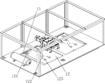
Fig. 1 is the structural representation of continous way sealing machine of the present invention;
Fig. 2 is the front view of continous way sealing machine of the present invention;
Fig. 3 is continous way sealing machine frame block diagram of the present invention;
Fig. 4 is driving chain of the present invention and template frame connection diagram;
Fig. 5 is rack rail of the present invention and sliding panel structural representation;
Fig. 6 is the synchronous material filling equipment mechanism of the present invention scheme drawing;
Fig. 7 is feeding unit structural representation of the present invention;
Fig. 8 is that the present invention is for the film unit structural representation;
Fig. 9 is film feeding block construction scheme drawing of the present invention;
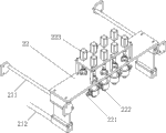
Figure 10 is the synchronous sealing-cutting device structural representation of the present invention;
Figure 11 is the synchronous sealing-cutting device front view of the present invention;
Figure 12 is the local structure for amplifying scheme drawing that A section among Figure 10 is shown.
The specific embodiment
For making the purpose, technical solutions and advantages of the present invention clearer, the present invention is described in further detail below in conjunction with accompanying drawing.
As shown in Figure 1 and Figure 2, continous way sealing machine of the present invention comprises frame 1, synchronous material filling device 2, film covering device 3, synchronous sealing-cutting device 4 and winder device 5.
With reference to Fig. 1, Fig. 3 and shown in Figure 4, described frame 1 is provided with driving device 13, described driving device comprises sprocket for main drive 131, from driving chain wheel 132, driving chain 133 and motor 134, described sprocket for main drive 131 is in transmission connection by rotating shaft 135 and described motor 134, and described driving chain 133 is installed on described sprocket for main drive 131 and describedly provides power to realize the transmission of described driving chain 133 from driving chain wheel 132 and by described motor 134.
Described driving chain 133 is connected with template frame by door shape attaching parts 136, thereby drives the running of described template frame.
Described template 137 is provided with registration mast 1371 in order to the location when described heat-sealing-cutting mechanism carries out sealing.
With reference to Fig. 2, shown in Figure 5, described frame is provided with guide rail 11, described sliding panel 12 be arranged on the described guide rail 11 and its length less than the length of described guide rail 11, described sliding panel 12 can move horizontally along described guide rail 111.
Described sliding panel 12 is provided with for the screw 121 of fixing described heat-sealing-cutting unit rack and described heat-sealing unit rack and the through hole 122 that can pass through for described cylinder piston.
Preferably, described sliding panel 12 also is provided with the screw 123 for further firm described heat-sealing-cutting module.
With reference to Fig. 1, shown in Figure 6, described synchronous material filling device comprises storing unit 21 and feeding unit 22, described storing unit 21 is fixedly arranged on the described frame 1, described feeding unit 22 utilizes sliding bar 211 to be installed on the described storing unit 21 and with described synchronous sealing-cutting device to utilize pipe link 212 affixed, and described storing unit 21 utilizes soft pipe connection with described feeding unit 22.
Described sliding bar 211 1 ends are fixed on the described storing unit 21, and the other end is connected with described feeding unit 22, and described feeding unit 22 can slide along described sliding bar 211.
When described servomotor makes slide plate horizontal slip on frame 1, be connected to the also thereupon horizontal slip of described synchronous sealing-cutting device on the described frame, the described storing unit 21 affixed by described pipe link 212 and described synchronous sealing-cutting device also moves along described sliding bar 211 thereupon, and makes coupled described feeding unit do horizontal slip along rack rail by pipe link.
Preferably, described storing unit 21 is provided with material inlet valve 213, is used for replenishing material.
As shown in Figure 7, described feeding unit 22 comprises inlet point 221 and discharging opening 222, described inlet point 221 utilizes flexible pipe to be communicated with described storing unit, and described feeding unit 22 is provided with cylinder 223, and described cylinder is controlled the opening and closing of described discharging opening 222 by piston.
Described feeding unit 22 is followed described synchronous sealing-cutting device by pipe link 212 drives and is reciprocatingly slided along doing along described sliding bar 211, and by the unlatching of the described discharging opening 222 of described cylinder 223 controls with closed, when described feeding unit 22 is done when moving in the same way with described template, described discharging opening 222 is opened 22 pairs of described template material fillings of described feeding unit; Otherwise described feeding unit 22 slides along guide rail after finishing the template material filling, and direction is opposite with described template sense of motion, at this moment described discharging opening 222 closures.
Need to prove that described feeding unit 22 is identical with described template kinematic velocity along described sliding bar 211 sliding velocitys, in finishing the process of material filling, keep relative static conditions with described template.
Be the present invention as shown in Figure 8 for the film unit structural representation, described film covering device comprises for film unit and film feeding unit, described for film unit comprise for film motor 311 and with the described membrane-feeding shaft 312 that is in transmission connection for film motor 311.
The described film unit that supplies also is provided with school film device 313, and described school film device comprises that spring 3131 and position-limited lever 3132 are to adapt to the template of different size.
When template replacement, need to adjust so that packaging film can cover described template fully for the film unit position described, described school film device 313 is by utilizing two ends spring 3131 to realize the position adjustment of described membrane-feeding shaft 312, and utilizes described position-limited lever 3132 that its position is fixed.
Fig. 9 is film feeding block construction scheme drawing of the present invention, described film feeding unit comprises connecting gear 321 and control mechanism 322, described connecting gear comprises main transmission shaft 3211, from transmission shaft 3212, light probe 3213 and the second servomotor 3214, described main transmission shaft 3211 is in transmission connection with described the second servomotor 3214, describedly contact cooperation from transmission shaft 3212 with 3211 of described main transmission shafts, described control mechanism 322 comprises movable axis 3221, movable axial trough 3222 and approach switch 3223, and described movable axis 3221 can slide along described movable axial trough 3222.
When described the second servomotor 3214 running, described main transmission shaft 3211 drives described from transmission shaft 3212 runnings, and the friction force that two transmission shaft axial plane touching positions form drives packaging film and forwards.
The described film feeding of described the second servomotor 3214 controls unit reaches the effect of accurate film feeding.
Preferably, described approach switch 3223 comprises starting switch 32231 and cutoff switch 32232, described starting switch 32231 is arranged near described movable axial trough 3222 upper end positions, and described cutoff switch 32232 is arranged near described movable axial trough 3222 lower end positions.
Preferably, described control mechanism 322 also is provided with leads film axle 3224, describedly leads that film axle 3224 vertically highly is higher than the vertical height of described cutoff switch 32232 and between described movable axial trough 3222 and described connecting gear 321.
Preferably, when described confession film unit vertically highly is lower than the vertical height of described starting switch 32231, also need arrange second and lead film axle 3225 between described movable axial trough 3222 and described confession film unit, described second leads film axle 3225 vertically highly is higher than vertically height of described starting switch 32231, packaging film is led on the film axle 3225 end section from described second and is passed and walk around described movable axis 3221 rear surfaces, lay out from described film axle 3224 upper end faces of leading at last, described movable axis 3221 place's shapes in an angle, this packaging film tightens up when described connecting gear 322 transmits packaging film, because tension force own makes described movable axis 3221 move up along described movable axial trough 3222, until arrive described starting switch 32231 positions, described starting switch 32231 detects the described movable axis 3221 rear described film electric motor starting work that supply, the described film unit that supplies begins to put film, because the described film unit that supplies is put film speed greater than described film feeding unit film feeding speed, packaging film becomes slack, tension force disappears, described movable axis 3221 since own wt along described loose slot 3222 down slidings, when sliding into described cutoff switch 32232, described film placing mechanism motor shuts down, described film feeding unit continues film feeding, described packaging film tightens up, and repeats above-mentioned for membrane process.
Preferably, for the length that makes film feeding more accurate, to save material, described film feeding unit also is provided with light probe 323, be used for the next further accurately control film feeding length of sign on the identification packaging film, described light probe is arranged near described film axle 3224 positions of leading, when described film feeding unit stops film feeding, described light probe 323 just detects the packaging film colour code that pre-sets, then error does not appear in film feeding unit film feeding length, if described light probe 323 did not detect the packaging film colour code that pre-sets when described film feeding unit stopped film feeding, then mistake appears in described film feeding unit film feeding length, and this moment, equipment suspended running and warning reminding.
Preferably, described light probe 3113 also is provided with sliding bar 32131, and described light probe 3213 moves forward and backward along described sliding bar 32131 along described template direction of transfer and the direction translation vertical with described template direction of transfer, to adapt to the template of different in width.
Preferably, described connecting gear also is provided with smooth 3215, and described smooth 3215 is used for packaging film entirely is overlying on the described template, avoids wrinkling.
With reference to Fig. 2, Fig. 5, Figure 10 and Figure 11, described synchronous sealing-cutting device 4 comprises the first servomotor 41 and heat-sealing-cutting mechanism, described the first servomotor 41 is fixedly arranged on the described frame, described the first servomotor 41 is connected with described heat-sealing-cutting mechanism driving, described heat-sealing-cutting mechanism is installed on the described sliding panel 12, and described heat-sealing-cutting mechanism can slide along described rack rail 11 with sliding panel 12 under described the first servomotor 41 drives.
Described heat-sealing-cutting mechanism comprises heat-sealing-cutting unit 421 and heat-sealing unit 422, described heat-sealing-cutting unit 421 and described heat-sealing unit 422 are installed on respectively on the described sliding panel 12, described sliding panel 12 is by guide rail 11 and described frame 1 sliding block joint, described sliding panel 12 is fixedly installed driving rack 121, described the first servomotor 41 is fixedly arranged on the described frame 1 and with described driving rack 121 and is connected with a joggle, when described the first servomotor 41 running, by the driving rack 121 with its engagement described sliding panel 12 is moved along described guide rail, thereby drive described heat-sealing-cutting unit 421 and described heat-sealing unit 422 and described feeding unit synchronization action under the driving of described the first servomotor 41.
Described heat-sealing-cutting unit 421 comprises support 4211, cylinder 4212 and heat-sealing-cutting module 4213, described support 4211 is installed on the described sliding panel 12 and can slides along described rack rail 11, described cylinder 4212 is installed on the described sliding panel 12, described heat-sealing-cutting module 4213 is connected with the piston rod 42121 of described cylinder 4212, described support 4211 lower ends and described heat-sealing-cutting module 4213 positions are provided with follow block 4214 accordingly, and described heat-sealing-cutting module 4213 and described follow block 4214 lay respectively at the above and below of described template frame.
Described support 4211 comprises upper cover plate 42111, lower cover 42112 and pillar 42113, and described pillar 42113 is divided into two sections and tightens together with described frame upper sliding plate 12.
Preferably, for further firm described heat-sealing-cutting module 4213, also utilize many pillars 42131 that it is connected with described sliding panel 12.
Described cylinder comprises the first cylinder 42121, the second cylinder 42122, and described the first cylinder block is connected with the cylinder body of described the second cylinder, and described the first cylinder piston rod is connected with described upper cover plate, and described the second cylinder piston rod 421221 is connected with described pressing plate.
Described the second cylinder piston rod 421221 is connected with the first pressing plate 4215, described the first pressing plate 4215 is provided with inverted T-shaped projection 42151, be provided with accordingly the second pressing plate 4216 with described the first pressing plate 4215, described the second pressing plate 4216 is provided with the inverted T-shaped groove 42161 corresponding with described the first pressing plate 4215, and described the first pressing plate 4215 can relative slidings occur along groove 42161 with described the second pressing plate 4216.
Preferably, described the first pressing plate 4215 and described the second pressing plate 4216 are fastening by nut, and be provided with handle 4217, can described the second pressing plate 4216 be pulled out along the direction vertical with groove 42161 cross sections by handle 4217 when needs are changed heat-sealing-cutting module 4213 parts, described heat-sealing-cutting module 4213 parts can be adjusted replacing according to the template model on the described template frame.
As shown in figure 12, described heat-sealing-cutting module 4213 comprises heat-sealing-cutting mechanism 42132 and cutting knife 42133.
Described heat-sealing unit 422 is identical with described heat-sealing-cutting unit 421 structures except not being provided with the cutting knife its structure.
Described the first servomotor drives described heat-sealing-cutting mechanism 42 and described feeding unit moves back and forth, described cylinder piston 42121 downward punching presses when described heat-sealing-cutting mechanism 42 direction of slips are consistent with described template direction of transfer, the flow process that described heat-sealing-cutting mechanism 42 finishes the heat-sealing bonding of packaging film and cuts film, in this process, described heat-sealing-cutting mechanism 42 kinematic velocitys are consistent with described template transfer rate, and both keep relative static conditions.
Above disclosed is a kind of preferred embodiment of the present invention only, certainly can not limit with this interest field of the present invention, and the equivalent variations of therefore doing according to claim of the present invention still belongs to the scope that the present invention is contained.
Claims (10)
1. continous way sealing machine, comprise frame, driving device, synchronous material filling device, film covering device, synchronous sealing-cutting device and winder device, described driving device drives template frame and turns round forward, described template frame is used for placing the template of different size, described synchronous material filling device, described film covering device and described winder device are arranged on the described frame, it is characterized in that:
Described synchronous material filling device comprises storing unit and feeding unit, described storing unit is fixedly arranged on the described frame, described feeding unit utilizes sliding bar to be installed on the described storing unit and with described synchronous sealing-cutting device to utilize pipe link affixed, and described storing unit is communicated with described feeding unit;
Described synchronous sealing-cutting device comprises heat-sealing-cutting mechanism and the first servomotor, described heat-sealing-cutting mechanism comprises heat-sealing-cutting unit and heat-sealing unit, described heat-sealing-cutting unit and heat-sealing unit interconnect by sliding panel, described sliding panel is by guide rail and described frame sliding block joint, described sliding panel is fixedly installed driving rack, described the first servomotor is fixedly arranged on the described frame and with described driving rack and is connected with a joggle, described heat-sealing-cutting unit and described heat-sealing unit and described feeding unit synchronization action under the driving of described the first servomotor.
2. continous way sealing machine according to claim 1, it is characterized in that, described heat-sealing-cutting unit comprises support, cylinder and heat-sealing-cutting module, described support is installed on the described sliding panel, described cylinder is installed on the described sliding panel, described heat-sealing-cutting module is connected with the piston rod of described cylinder, and described support lower end and described heat-sealing-cutting module position are provided with follow block accordingly, and described heat-sealing-cutting module and described follow block lay respectively at the above and below of described template frame.
3. continous way sealing machine according to claim 2, it is characterized in that, described cylinder piston rod is connected with the first pressing plate, described the first pressing plate is provided with the inverted T-shaped projection, described the first pressing plate is provided with the second pressing plate accordingly, described the second pressing plate is provided with the inverted T-shaped groove corresponding with described the first pressing plate, and described first, second pressing plate can be along groove generation relative sliding.
4. continous way sealing machine according to claim 1, it is characterized in that described feeding unit comprises inlet point and discharging opening, described inlet point utilizes flexible pipe to be communicated with described storing unit, described feeding unit is provided with cylinder, and described cylinder is controlled the opening and closing of described discharging opening by piston.
5. continous way sealing machine according to claim 1, it is characterized in that, described film covering device comprises for film unit and film feeding unit, reach and the described membrane-feeding shaft that supplies the film motor-driven to be connected described comprising for the film motor for film unit, described film feeding unit comprises connecting gear and control mechanism, described connecting gear comprises main transmission shaft, from transmission shaft, light probe and the second servomotor, described main transmission shaft is connected with described the second servo motor transmission, describedly contact cooperation from transmission shaft with the described main axial plane that transmits, described control mechanism comprises movable axis, movable axial trough and approach switch, described movable axis can slide along described movable axial trough.
6. continous way sealing machine according to claim 5, it is characterized in that, described approach switch comprises starting switch and cutoff switch, described starting switch is arranged at described movable axial trough upper end position, described cutoff switch is arranged at described movable axial trough lower end position, and described starting switch and described cutoff switch are controlled described operation for the film motor and stopped.
7. continous way sealing machine according to claim 1, it is characterized in that, described driving device comprises that sprocket for main drive, driving chain reach from driving chain wheel, described driving chain is installed in described sprocket for main drive and from driving chain wheel, described sprocket for main drive and motor output end are in transmission connection, described driving chain is captiveed joint with described template frame, and template is fixed on the described template frame.
8. continous way sealing machine according to claim 1, it is characterized in that, described plastic film residue collect mechanism comprises tightening system, winder spool and motor, and described motor is provided with engaging and disengaging gear, and described tightening system is connected with described motor-driven and is in transmission connection by belt conveyor and described winder spool.
9. continous way sealing machine according to claim 5, it is characterized in that, the described film unit that supplies is provided with the school film device, and described school film device comprises spring and position-limited lever, and it is described for the film unit position corresponding with described template to cooperate described spring to adjust by described position-limited lever.
10. continous way sealing machine according to claim 1 is characterized in that described frame also is provided with the compression cup device, and described compression cup device comprises platen and cylinder, and described platen is connected with described cylinder piston rod.
Priority Applications (3)
| Application Number | Priority Date | Filing Date | Title |
|---|---|---|---|
| CN 201110302454 CN102328755B (en) | 2011-10-09 | 2011-10-09 | Continuous sealing and cutting machine |
| PCT/CN2011/081420 WO2013053154A1 (en) | 2011-10-09 | 2011-10-27 | Continuous sealing and cutting machine |
| EP11873863.2A EP2774859B1 (en) | 2011-10-09 | 2011-10-27 | Continuous sealing and cutting machine |
Applications Claiming Priority (1)
| Application Number | Priority Date | Filing Date | Title |
|---|---|---|---|
| CN 201110302454 CN102328755B (en) | 2011-10-09 | 2011-10-09 | Continuous sealing and cutting machine |
Publications (2)
| Publication Number | Publication Date |
|---|---|
| CN102328755A CN102328755A (en) | 2012-01-25 |
| CN102328755B true CN102328755B (en) | 2013-01-02 |
Family
ID=45480776
Family Applications (1)
| Application Number | Title | Priority Date | Filing Date |
|---|---|---|---|
| CN 201110302454 Expired - Fee Related CN102328755B (en) | 2011-10-09 | 2011-10-09 | Continuous sealing and cutting machine |
Country Status (3)
| Country | Link |
|---|---|
| EP (1) | EP2774859B1 (en) |
| CN (1) | CN102328755B (en) |
| WO (1) | WO2013053154A1 (en) |
Families Citing this family (12)
| Publication number | Priority date | Publication date | Assignee | Title |
|---|---|---|---|---|
| CN103264568B (en) * | 2013-04-19 | 2014-12-24 | 瑞安市诚达机械有限公司 | Heat sealing and cutting mechanism of paper-plastic machine |
| CN104925332B (en) * | 2015-05-29 | 2017-03-08 | 辽宁春光机械有限公司 | Automatic Liquid filler list props up blanking units |
| CN106494702A (en) * | 2015-09-04 | 2017-03-15 | 广东唐城美特智能工具有限公司 | Pneumatic nail production automation line |
| CN105857666B (en) * | 2016-05-21 | 2018-06-08 | 广东粤东机械实业有限公司 | The epiphragma detent mechanism of filling sealer |
| CN107600488A (en) * | 2017-08-30 | 2018-01-19 | 蚌埠市同升滤清器有限公司 | A kind of PVC foam plate packing apparatus |
| CN107877569A (en) * | 2017-11-08 | 2018-04-06 | 贵州省黄平县乐源旅游特色食品有限公司 | A kind of packaging film cutter device |
| CN108146015A (en) * | 2017-12-29 | 2018-06-12 | 长兴天誉包装股份有限公司 | A kind of cardboard cutter device of automatic charging |
| CN111941493B (en) * | 2019-05-16 | 2022-04-05 | 苏州巨一智能装备有限公司 | Clamping and cutting device and method for dielectric film |
| CN110104241A (en) * | 2019-05-28 | 2019-08-09 | 深圳市永创自动化设备有限公司 | A kind of bottom sealed plastic packaging machine |
| CN113320770A (en) * | 2021-06-21 | 2021-08-31 | 斯蒂尔机械设备(嘉兴)有限公司 | Efficient full-automatic packaging machine |
| CN114771925A (en) * | 2022-04-06 | 2022-07-22 | 王远浩 | Film pasting device |
| CN115285395B (en) * | 2022-08-17 | 2023-07-04 | 绍兴市盈创医疗科技有限公司 | Packaging equipment |
Citations (7)
| Publication number | Priority date | Publication date | Assignee | Title |
|---|---|---|---|---|
| US4819413A (en) * | 1980-01-23 | 1989-04-11 | Consumers Glass Company Limited | Precision lid fit filling machine |
| WO1998039210A1 (en) * | 1997-03-05 | 1998-09-11 | Tetra Laval Holdings & Finance, S.A. | Orienting apparatus for an orientationally sensitive closure |
| EP1389166B1 (en) * | 2001-05-12 | 2005-04-06 | Robert Bosch Gmbh | Device for inserting packing items into packing material |
| JP4053207B2 (en) * | 2000-04-03 | 2008-02-27 | シーケーディ株式会社 | Molding, filling and sealing device |
| CN201086834Y (en) * | 2007-08-30 | 2008-07-16 | 江苏永和制药机械有限公司 | Hot sealing device of filling and sealing machine for easily folded plastic bottle |
| CN201343150Y (en) * | 2009-01-20 | 2009-11-11 | 广东粤东机械实业有限公司 | Filling device for multifunctional filling cap-rotating sealing machine |
| JP4360120B2 (en) * | 2003-05-22 | 2009-11-11 | 澁谷工業株式会社 | Filling seal device |
Family Cites Families (11)
| Publication number | Priority date | Publication date | Assignee | Title |
|---|---|---|---|---|
| US3775934A (en) * | 1972-04-06 | 1973-12-04 | Purity Packaging Ltd | Method of and apparatus for applying caps to containers |
| US3965656A (en) * | 1974-05-16 | 1976-06-29 | Solo Cup Company | Cup filling and capping apparatus |
| US4077180A (en) * | 1976-06-17 | 1978-03-07 | Portion Packaging, Inc. | Method and apparatus for packaging fluent material |
| US4349997A (en) * | 1980-04-21 | 1982-09-21 | Mitsubishi Jukogyo Kabushiki Kaisha | Device for enabling registry of operations in an apparatus for continuously forming containers filled with material |
| US5443150A (en) * | 1993-09-23 | 1995-08-22 | Rapidpak, Inc. | Apparatus for advancing preformed containers |
| DE19750075C2 (en) * | 1997-11-12 | 2002-11-14 | Jagenberg Ag | Process for separating cover sheet films from a plastic film web and device for carrying out the process |
| EA200200139A1 (en) * | 1999-07-27 | 2002-08-29 | Санфорд Редмонд Инк. | COMPACT MACHINE FOR FORMING, FILLING AND SEALING OF PACKAGES |
| ITMO20030042A1 (en) * | 2003-02-24 | 2004-08-25 | Green Pack Srl | METHOD AND APPARATUS TO OBTAIN FILLED CONTAINERS. |
| ITMO20040151A1 (en) * | 2004-06-17 | 2004-09-17 | Evifill S R L | METHOD AND PLANT FOR THE MANUFACTURE OF PRODUCT PACKAGES |
| CN201169532Y (en) * | 2008-03-13 | 2008-12-24 | 山东省蓬莱制药机械厂有限公司 | Numerical control continuous liquid filling machine |
| CN202279243U (en) * | 2011-10-09 | 2012-06-20 | 广东粤东机械实业有限公司 | Continuous sealing and cutting machine |
-
2011
- 2011-10-09 CN CN 201110302454 patent/CN102328755B/en not_active Expired - Fee Related
- 2011-10-27 WO PCT/CN2011/081420 patent/WO2013053154A1/en active Application Filing
- 2011-10-27 EP EP11873863.2A patent/EP2774859B1/en not_active Not-in-force
Patent Citations (7)
| Publication number | Priority date | Publication date | Assignee | Title |
|---|---|---|---|---|
| US4819413A (en) * | 1980-01-23 | 1989-04-11 | Consumers Glass Company Limited | Precision lid fit filling machine |
| WO1998039210A1 (en) * | 1997-03-05 | 1998-09-11 | Tetra Laval Holdings & Finance, S.A. | Orienting apparatus for an orientationally sensitive closure |
| JP4053207B2 (en) * | 2000-04-03 | 2008-02-27 | シーケーディ株式会社 | Molding, filling and sealing device |
| EP1389166B1 (en) * | 2001-05-12 | 2005-04-06 | Robert Bosch Gmbh | Device for inserting packing items into packing material |
| JP4360120B2 (en) * | 2003-05-22 | 2009-11-11 | 澁谷工業株式会社 | Filling seal device |
| CN201086834Y (en) * | 2007-08-30 | 2008-07-16 | 江苏永和制药机械有限公司 | Hot sealing device of filling and sealing machine for easily folded plastic bottle |
| CN201343150Y (en) * | 2009-01-20 | 2009-11-11 | 广东粤东机械实业有限公司 | Filling device for multifunctional filling cap-rotating sealing machine |
Non-Patent Citations (1)
| Title |
|---|
| JP特开4053207B2 2008.02.27 |
Also Published As
| Publication number | Publication date |
|---|---|
| EP2774859A1 (en) | 2014-09-10 |
| WO2013053154A1 (en) | 2013-04-18 |
| EP2774859A4 (en) | 2015-09-02 |
| CN102328755A (en) | 2012-01-25 |
| EP2774859B1 (en) | 2016-12-07 |
Similar Documents
| Publication | Publication Date | Title |
|---|---|---|
| CN102328755B (en) | Continuous sealing and cutting machine | |
| CN105691740B (en) | A kind of flexible intelligent bagging device | |
| CN102173102B (en) | Device for installing carton handles | |
| CN202062706U (en) | Carton handle installing equipment | |
| CN201907852U (en) | Automatic dowel distributing mechanism | |
| CN104925281A (en) | Soft bag production line | |
| CN201280227Y (en) | Quick compact type non-PVC film double-flexible pipe full-automatic bag production filling and closing machine | |
| CN111572842A (en) | Injection molding filling machine and working method thereof | |
| CN103949605A (en) | Automatic button turning machine | |
| CN205554758U (en) | Flexible intelligence cover bag equipment | |
| CN204776121U (en) | Soft bag production line | |
| CN110281588A (en) | A kind of isolated packing bag bag-making equipment | |
| CN106541621A (en) | A kind of seal device | |
| CN202279243U (en) | Continuous sealing and cutting machine | |
| CN203804519U (en) | Automatic bearing pressing mechanism | |
| CN202242093U (en) | Full automatic square-bottom bag machine | |
| CN203921233U (en) | Bag body fill type PP TYPE bag-making equipment | |
| CN203590684U (en) | Automatic material receiving and feeding apparatus and full-automatic device for mounting reinforcement sheet on PFC | |
| CN110422413A (en) | The flat bubble-cap machine of high speed | |
| CN201136604Y (en) | Film cutting device for heat-shrinkable film packaging machine | |
| CN202138583U (en) | Heat seal mechanism of packing machine | |
| CN203624001U (en) | Automatic packaging machine | |
| CN104443487B (en) | Disposable paper-plastic container film sealing machine | |
| CN204323734U (en) | A kind of disposable paper-plastic container film sealing machine | |
| CN103331946A (en) | Handle welding bag making device |
Legal Events
| Date | Code | Title | Description |
|---|---|---|---|
| C06 | Publication | ||
| PB01 | Publication | ||
| C10 | Entry into substantive examination | ||
| SE01 | Entry into force of request for substantive examination | ||
| C14 | Grant of patent or utility model | ||
| GR01 | Patent grant | ||
| CF01 | Termination of patent right due to non-payment of annual fee | ||
| CF01 | Termination of patent right due to non-payment of annual fee |
Granted publication date: 20130102 Termination date: 20201009 |